
2.1: Pre-lab Exercises
- Page ID
- 47354

Coherence and Interferometry
The Pre-Lab Exercises must be completed BEFORE entering the Lab. In your lab notebook record data, explain phenomena you observe, and answer the questions asked. Remember to answer all questions in your lab notebook in a neat and orderly fashion. No data are to be taken on these laboratory sheets. Tables provided herein are simply examples of how to record data into your laboratory notebooks. Expect the in-lab portion of this exercise to take about 3 hours.
PL 2.1 - Get Prepared to Start the Laboratory Exercises
Read the entire laboratory handout, and be prepared to answer questions before, during and after the lab session. Determine all the equations and constants that may be needed in order to perform all the laboratory exercises. Write them all down in your laboratory notebook before entering the Lab. This will ensure that you take all necessary data while in the Lab in order to complete the lab write-up. This preparatory work will also count toward your Lab Exercise grade.
PL 2.2 - Michelson interferometer Considerations
For this exercise, you are greatly encouraged to work in groups of 2-4 people.
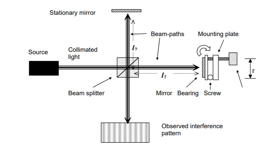
On Lab day, you will be asked to build and analyze one of the most commonly used interferometers in science and industry - a Michelson interferometer. Michelson interferometers are used in coherence detection apparatus, like FTIRs (Fourier Transform Infrared Spectroscopy), in countless mechanical systems (to maintain precise alignment), as well as in the proposed space-based Laser Interferometer Gravitational Wave Observatory (LIGO), just to cite a few examples. Michelson interferometers are relatively simple to build, easy to align and have many advantages over alternate interferometer designs. In this pre-lab exercise, you are asked to analyze a Michelson interferometer that will be used to measure the coherence length of a diode laser source. This interferometer has one stationary arm, and one translatable (moving arm) as shown in the diagram below.
First we would like you to determine the angular accuracy required to perform a ‘rough alignment’ of a Michelson interferometer.
- Using collimated 632.8 nm (wavelength) light, you must determine the angular accuracy needed to form fringes of 1mm spacing on the test plane, given that the nominal arm length of the Michelson interferometer is l1 = l2 = 20 cm.
- If the movable mirror is gimbaled from a ball bearing on one edge of a one-axis angular-rotation mount which uses a micrometer screw located at a distance r = 2.5 cm away at the opposite edge of the mirror, what is the corresponding distance the micrometer must travel to rotate the mirror between the angular alignment calculated above and the state of ‘perfect’ alignment (both output beams perfectly collinear)? Below is a diagram to illustrate the principle of the Michelson interferometer.
- If the light from the source is divergent (spherical waves instead of plane waves), what would the fringe pattern look like for a ‘perfectly’ aligned Michelson interferometer?
- Although you are not being asked to do a full design of a coherence-detecting Michelson interferometer, you should think about how all of the parts listed in the table below could be used to build one. So please make a drawing in your lab notebook showing how all of the optical components listed below could be used to build a coherence-detection Michelson interferometer.
Table of Available Components
| Qty | Description |
| 2 | 1” two-axis mirrors |
| 1 | 0.5” cube beam splitter |
| 1 | 25 micron pinhole |
| 2 | Variable irises |
| 1 | Short focal-length 20x objective |
| 1 | Long focal-length biconvex lens (collimating lens) |
| 1 | 3” linear translation stage w/micrometer |
| 1 set | Posts, post holders and other mounting hardware |
| 1 | 1’x1’ optical breadboard |
| 1 | He-Ne laser used for alignment |
“The strongest arguments prove nothing so long as the conclusions are not verified by experience. Experimental science is the queen of sciences and the goal of all speculation.” -- Roger Bacon (1214-1294) English philosopher, scientist, optical experimentalist