
3.3.2: Flow over a finite wing
- Page ID
- 78108

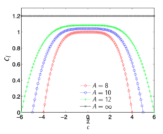
Figure 3.21: Sketch of the coefficient of lift along a wingspan.
Figure 3.21 shows the distribution of coefficient of lift along the wingspan of four rectangular wings flying in incompressible flow with an attack angle of 10 [deg]. The four wings use the same aerodynamic airfoil and differ in the enlargement (8,10,12, and infinity). It can be observed that if the enlargement is infinity the wing behaves as the bi-dimensional airfoil \(y\) (\(c_l (y)\) constant). On the other hand, if the enlargement is finite, \(c_l (y)\) shows a maximum in the root of the wing (\(y = 0\)) and goes to zero in the tip of the wing (\(y/c = A/2\)). As the enlargement decreases, the maximum \(c_l (y)\) also decreases.
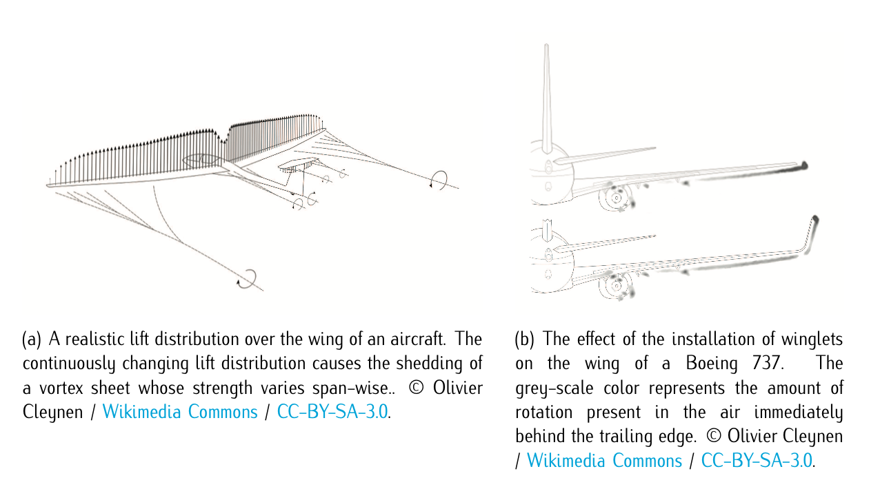
Figure 3.22: Whirlwind trail
The explanation behind this behavior is due to the difference of pressures between extrados and intrados. In particular, in the region close to the marginal border, there is an air current surrounding the marginal border which passes from the intrados, where the pressure is higher, to extrados, where the pressure is lower, giving rise to two vortexes, one in each border rotating clockwise and counterclockwise. This phenomena produces downstream a whirlwind trail. Figure 3.22 illustrates it.
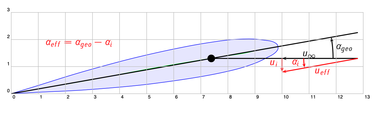
Figure 3.23: Effective angle of attack.
The presence of this trail modifies the fluid field and, in particular, modifies the velocity each wing airfoil sees. In addition to the freestream velocity, \(u_{\infty}\), a vertical induced velocity, \(u_i\), must be added (See Figure 3.23). The closer to the marginal border, the higher the induced velocity is. Therefore, the effective angle of attack of the airfoil is lower that the geometric angle, which explains both the reduction in the coefficient of lift (with respect to the bi-dimensional coefficient) and the fact that this reduction is higher when one gets closer to the marginal border.