
6.2.6: Nozzles
- Page ID
- 78143

The final stage of the jet engine is the nozzle. The nozzle has three functions, namely: a) to generate thrust; b) to conduct the exhaust gases back to the free-stream conditions; and c) to establish the mass flow rate through the engine by setting the exhaust area. The nozzle lays downstream the turbine.3
There are different shapes and sizes depending on the type of aircraft performance. Simple turbojets and turboprops typically have fixed-geometry convergent nozzles. Turbofan engines sometimes employ a coannular nozzle where the core flow exits the center nozzle while the fan flow exits the annular nozzle. After-burning turbojets and some turbofans often incorporate variable-geometry convergent-divergent nozzles (also referred to as de Laval nozzles), where the flow is first compress to flow through the convergent throat, and then is expanded (typically to supersonic velocities) through the divergent section.
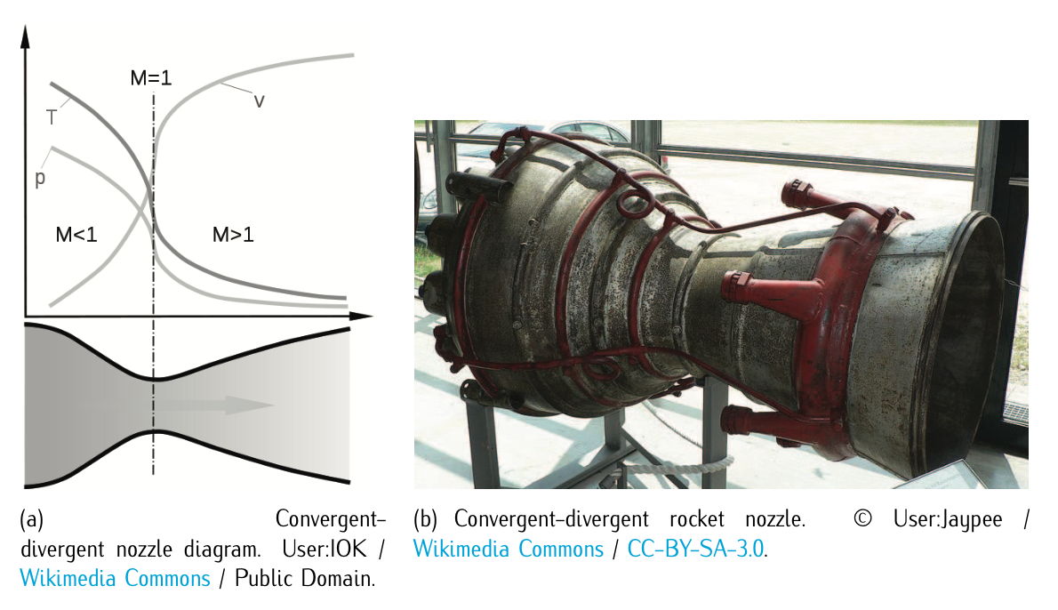
Figure 6.10: Convergent-divergent nozzle. In the left-land side, the figure shows approximate flow velovity (\(v\)), together with the effect on temperature (\(T\)) and pressure (\(p\)).
Let us now move on analyzing in brief the equations governing the evolution of the flow in the nozzle. The nozzle exerts no work on the flow, and thus both the stagnation temperature and the stagnation pressure can be considered constant. Recalling the station number from Figure 6.2, we write:
\[\dfrac{p_{8t}}{p_{5t}} = \left (\dfrac{T_{8t}}{T_{5t}} \right )^{\tfrac{\gamma}{(\gamma - 1)}} = 1,\nonumber\]
where 5 corresponds to the turbine exit and 8 to the nozzle throat.
The stagnation pressure at the exit of the nozzle is equal to the free-stream static pressure, unless the exiting flow is expanded to supersonic conditions (a convergent- divergent nozzle). The nozzle pressure ratio (NPR) is defined as:
\[NPR = \dfrac{p_{8t}}{p_8} = \dfrac{p_0}{p_8},\]
where \(p_{8t}\) is the stagnation nozzle pressure or the free-stream static pressure. In order to determine the total pressure at the nozzle throat \(p_8\), a term referred to as overall engine pressure ratio (EPR) is used. The EPR is defined to be the total pressure ratio across the engine, and can be expressed as follows:
\[EPR = \dfrac{p_{8t}}{p_{2t}} = \dfrac{p_{3t}}{p_{2t}} \dfrac{p_{4t}}{p_{3t}} \dfrac{p_{5t}}{p_{4t}} \dfrac{p_{8t}}{p_{5t}},\]
where the compressor, combustor, turbine, and nozzle stages are all represented.
Similarly, the Engine Temperature Ration (ETR) can be expressed as:
\[ETR = \dfrac{T_{8t}}{T_{2t}} = \dfrac{T_{3t}}{T_{2t}} \dfrac{T_{4t}}{T_{3t}} \dfrac{T_{5t}}{T_{4t}} \dfrac{T_{8t}}{T_{5t}},\]
from which the nozzle stagnation temperature (\(T_{8t}\)) can be calculated.
Considering Equation (6.2.1.7), isolating the exit velocity and doing some algebra, it yields:
\[u_e = u_8 = \sqrt{2c \eta_n T_{8t} \left [1 - (\dfrac{1}{NPR})^{\tfrac{\gamma - 1}{\gamma}} \right ]},\]
where \(\eta_n\) is the nozzle efficiency, which is normally very close to 1.
The nozzle performance equations work just as well for rocket engines except that rocket nozzles always expand the flow to some supersonic exit velocity.
Summing up, all the necessary relations between jet engine components have been stated in order to obtain the thrust developed by the jet engine. Notice that, as already pointed out in Equation (6.1.1.1), the thrust would be:
\[Thrust = \dot{m} \cdot (u_e - u_0).\]
3. Notice that in this description of the core elements of a jet engine the after-burner has been omitted. It there is one (fundamentally, for supersonic aircraft), it would located downstream the turbine and upstream the nozzle.