
9.3.2: The runway
- Page ID
- 78364

According to ICAO [4] a runway is:
defined as a rectangular area on a land aerodrome prepared for the landing and takeoff of aircraft.
Runways are typically build based on asphalt or concrete over a previously leveled and compacted surface. Runways are defined together with safety areas, that might be of compacted natural terrain. On both sides of the runway, there is the strip. In the heads of the runway we find a Stop-Way (SWY) area, a Clear-Way (CWY) area, and a Runway End Safety Area (RESA). All these areas are due to safety reasons and their specifications are stated by ICAO and can be consulted in ICAO [4]. Related to these safety areas, ICAO defines de following declared distances:
-
take-off run available (TORA): The length of runway declared available and suitable for the ground run of an aeroplane taking off.
-
take-off distance available (TODA): The length of the take-off run available plus the length of the clearway, if provided.
-
accelerate-stop distance available (ASDA): The length of the take-off run available plus the length of the stopway, if provided.
-
landing distance available (LDA): The length of runway which is declared available and suitable for the ground run of an aeroplane landing.
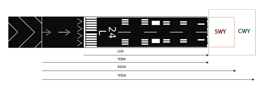
Figure 9.4: Runway declared distances. Adapted from © User:Mormegil / Wikimedia Commons / CC-BY-SA-3.0.
Figure 9.4 sketches them. Notice that in this figure the threshold has been displaced (limiting thus landings) and there is a pre-threshold area only allowed to be used as stopway for 06R’s take-offs. Please refer to Section 9.4.2 for more information on visual aids and markings. Please, refer to Exercise 1.4 as an illustrative instance.
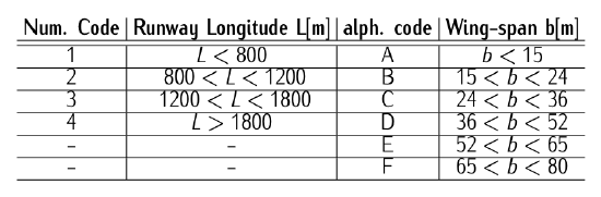
Table 9.3: Runway ICAO categories (alph. code refers to the type of aircraft). Data retrieved from ICAO [4].
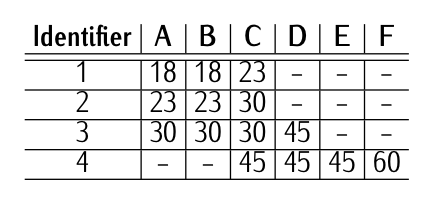
Table 9.4: Minimum runway’s width [m] ICAO identifiers. Data retrieved from ICAO [4].
Runway categories
ICAO has established different categories for the runways according to the size of the aircraft that can operate in such runways. The identifiers are two: a letter associated to the wing-span of the aircraft; and a number designating the longitude of the runway, measured in terms of reference field length as defined in Definition 9.5. Table 9.3 shows these categories. The width of the runways is obviously related with the category. It is shown in Table 9.4.
The minimum field length required for take-off at maximum certificated take-off mass, sea level, standard atmospheric conditions, still air and zero runway slope, as shown in the appropriate aeroplane flight manual prescribed by the certificating authority or equivalent data from the aeroplane manufacturer. Field length means balanced field length for aeroplanes, if applicable, or take-off distance in other cases.
For instance, Category 4 establishes a reference field length greater that 1800 m, however runways can be much longer up to 4500 m. Therefore, at the real operation conditions, the distances that aircraft actually need must be compensated, e.g., with the temperature of the airport, elevation of the airport, and slope of the runway. As an illustration, the same aircraft would need much less distance to take off in an airport located at sea level that in an airport located at 3000 [m]. Further insight on this will be given in Section 9.4.3. Please, refer to Exercise 1.5 as an illustrative instance.
Runway identifiers
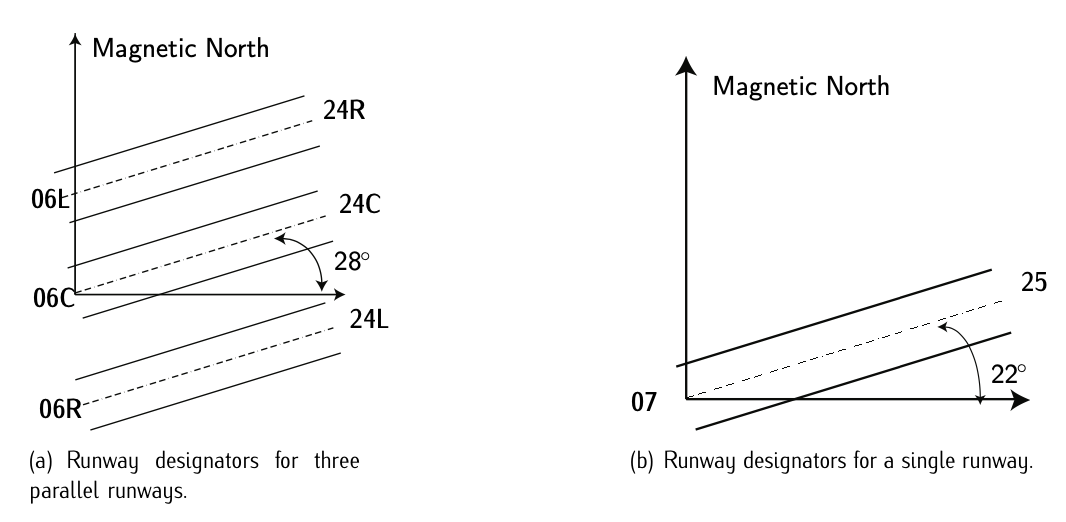
Figure 9.5: Runway designators.
Runways are identified attending at its geographical orientation, starting from the north and running clockwise, rounding to the closest tens of grades. Therefore, a runway which is being approach with a course of \(89^{\circ}\) (that is, approaching from West to East) will be designated 09. Obviously, in the other head of the runway there is a difference of \(180^{\circ}\), that is, the designator will be 27 (see Figure 9.3). Notice that the heads in courses near the North are identified as 36 instead of using 0. Figure 9.5.b illustrates an example.
When there exist parallel runways, as is the case of big airports such Madrid Barajas, a letter L (left) or right (R)3 is added prior to the number. L or R is added attending at what the pilot is seeing when approaching on his/her right and left. See for instance Figure 9.5.a, which shows an airport layout with three parallel runways.
Runways configuration
The most commonly used configurations are:
- Unique runway configuration.
- Cross runways configuration.
- V runways configuration.
- Parallel runways configuration.
- Double parallel runways configuration.
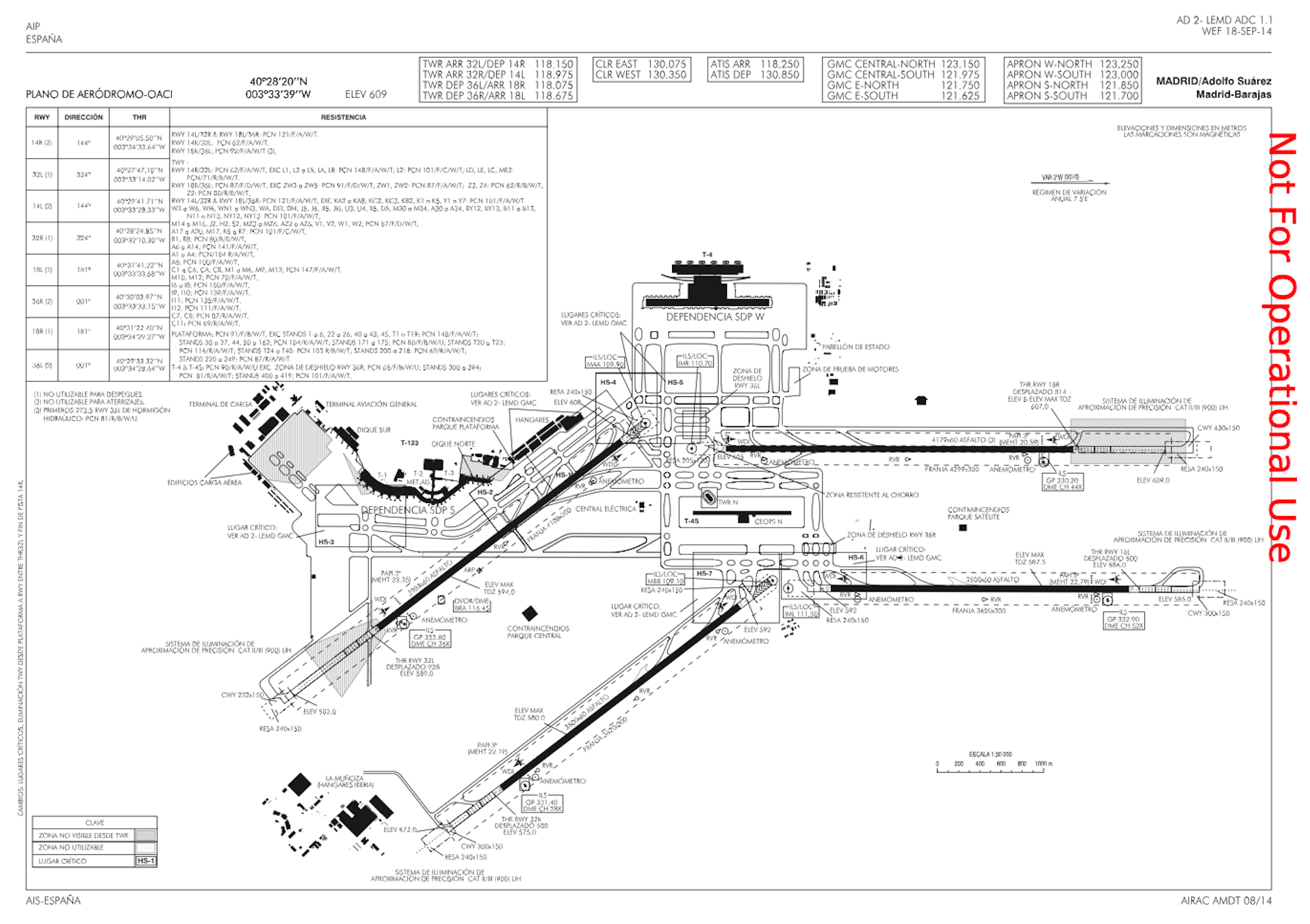
Figure 9.6: Adolfo Suarez Madrid Barajas layout chart. © AENA. / AIP AENA.
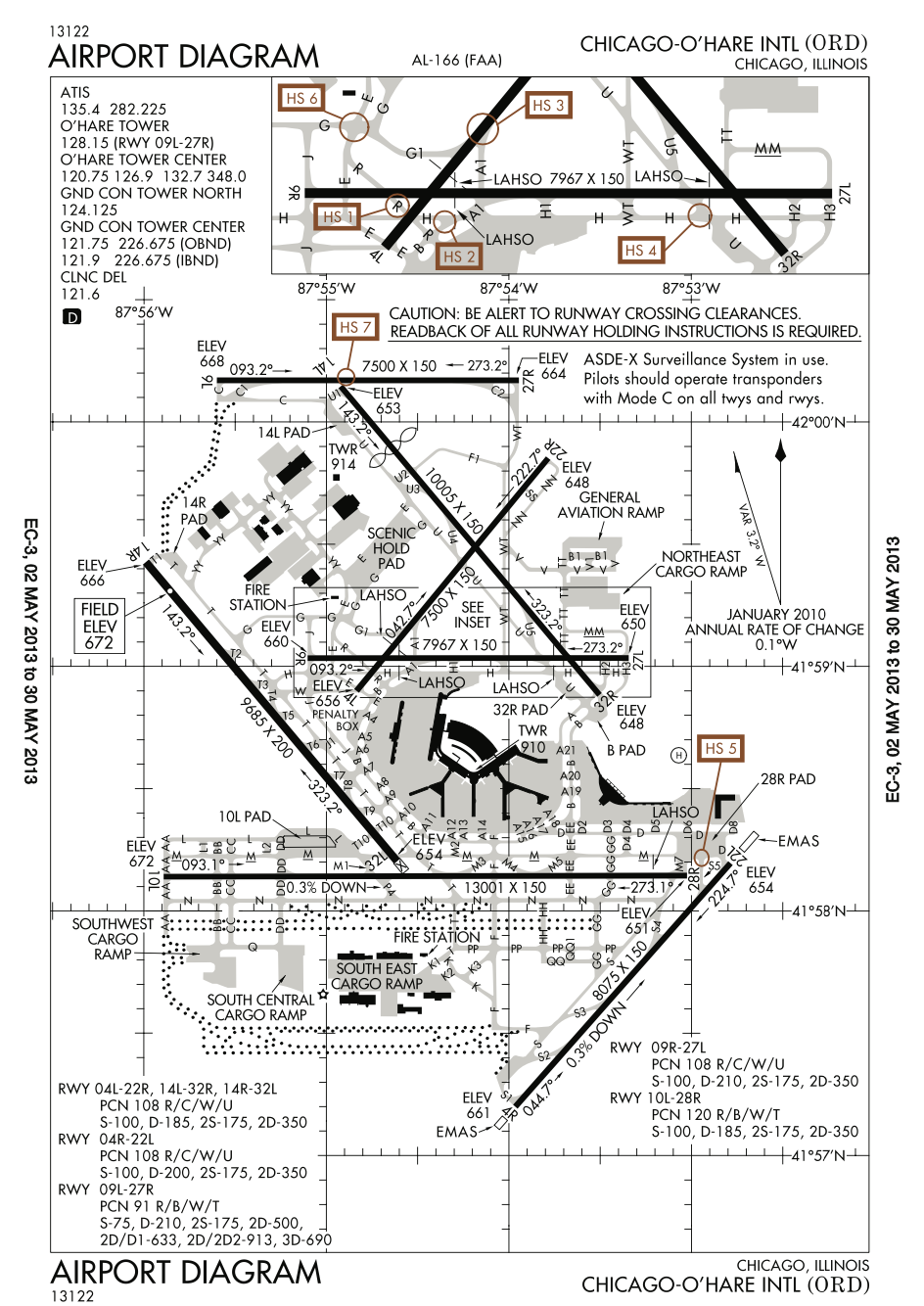
Figure 9.7: FAA airport diagram of O’Hare International Airport. © FAA. / Wikimedia Commons / Public domain.
Notice that these configurations are made attending at the design requirements. One key indicator is the forecasted demand, which determined whether is enough with one runway to cope with all expected demand. Another factor could be related to the dominant winds. If there are two dominant directions, we might be forced to design two runways in different directions not to cancel operation on a regular basis. An overview of different spanish airports layout can be consulted in AIP AENA. See Figure 9.6 and Figure 9.7.
Capacity of the runway
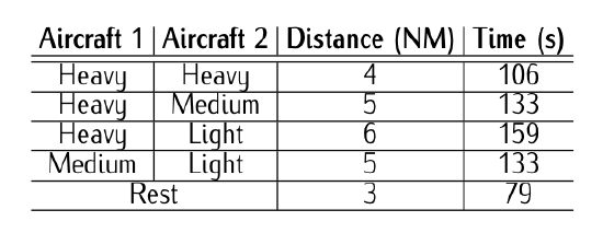
Table 9.5: ICAO minimum distance in airport operations. Heavy refers to aircraft with \(MTOW\) > 136000 [kg]. Medium refers to aircraft with 7000 < \(MTOW\) < 136000 [kg]. Any other aircraft with \(MTOW\) < 7000 [kg] are light. Data retrieved from ICAO [4].
As studied in Chapter 3, an aircraft generates two vortexes in the tips of the wing that travel backwards behind the aircraft. Such trails remain a long distance behind the aircraft and can disturb aircraft flying behind, becoming a potential danger. In order to prevent such danger, ICAO has established a required minimum separation. Table 9.5 shows these distances in airport operations, being aircraft 1 the preceding aircraft. These separations are the key factor that determines the capacity of a runway in nominal conditions. A single runway configuration might have a maximum capacity of approximately 50-60 movements per hour. In configurations with more than one runway, the capacity increases.
In general, the capacity of a runways depends on different factors, some based on the available infrastructure, and other related with airport operations:
- The conditions of Air Traffic Control (ATC) in approach and take-off.
- Longitude, orientation, and number of runways.
- The use of the system of runways for different operations (take-off and landing).
- The number, location, and characteristics of the rapid exit taxiways.
- The number of taxiways and the waiting points to runways heads.
- Mix of aircraft.
- Atmospheric conditions (wind, rain, fog, etc.)
- Conditions of the pavement.
- Type of visual aids.
- Approach and take off procedures.
- Interferences of the Terminal Maneuvering Area (TMA) with nearby airports or other flights (military, training, general aviation, etc.)
3. There might also exist C (center) in case of three parallel runways.