
3.3: Production of Steam - Fuel
- Page ID
- 48555

3.3 Production of Steam - Fuel
The fuel that has been used as a primary source for electricity for several years is coal. It has not been the only source but has been beneficial to the electricity industry because:
- coal has been the cheapest fuel, on $ per million Btu basis; natural gas has been strongly competitive primarily in recent years;
- at one time (recent), 60% of U.S. electricity was generated in coal-fired plants. Now ~40% from coal;
- approximately 80% of U.S. coal production is burned in electric plants.
However, the main reason we are considering switching away from coal is burning coal is one of the most challenging environmental problems.
For purposes of the course, we consider steam generation from coal as steam generation from biomass; both fuels are fairly similar.
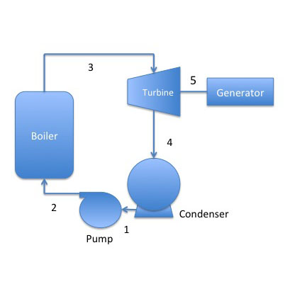
We want a high heat release rate, which is tied to the burning rate of fuel. Since coal is a solid fuel, it won't burn quickly if it is in chunks. So, the way to increase the burning rate is to increase the surface area of the coal; the way to increase the surface area is to pulverize the coal into very small particles. However, when the coal particles are small in size (something like flour), it makes it difficult to handle. It is hard to shovel something that is like dust or to support it on a grate. Instead, it is actually blown into the boiler unit with a current of air, which is called pulverized-coal firing or suspension firing. This is now the standard for electric power generation, abbreviated PC-fired water-tube boiler. Burning the coal produces heat; the heat is used to boil the water to steam; the steam moves across the turbine to move it; and the turbine turns the generator to produce electricity (see Figure 3.4). Through this sequence of transformations, the chemical potential energy of fuel (coal in this case) is converted to high-potential, high-voltage electricity for distribution to consumers. If you consider the net efficiency from the coal pile to the end of the plant, the plant efficiency is ~33%. Plants built more recently can be in the middle-high 30s range, while older plants may be in the mid-20s.
Credit: Dr. Caroline B. Clifford
Figure 3.4 above is an illustration of a coal-fired power plant that operates on a RANKINE cycle. A Rankine steam cycle is the way most steam plants operate (the most ideal way to operate an engine is the Carnot cycle; the Rankine cycle is a modified version of the Carnot cycle.)
The following steps are involved:
- Water is pumped at constant entropy to State 2 and into boiler.
- Liquid is heated at constant pressure State 3 (saturated steam).
- Steam expands at constant entropy through the turbine to State 4.
- Constant pressure transfer of heat in condenser.
- The turbine turns the engine to produce electricity.
For More Information
The following links provide some background information if you are interested:
The way to determine the efficiency is to look at the efficiency across each part of the plant. Losses can occur at each step of the process (see Figure 3.4). For a PC-fired modern power plant, assume operation at 2500 psi, with a steam temperature of 540°C, then the overall efficiency is 34%. Losses at each part include 1 & 2) heat losses in pipes and from the friction of the pump (efficiency of 92%); 3) heat losses and friction in the turbine (efficiency of 44%); 4) heat losses as the steam condenses back to water (efficiency of 85%), and 5) very little loss of efficiency from generator (efficiency of 99%). For every three rail cars of coal used to generate electricity, two cars of coal are lost to waste heat.
Figure 3.5 is an overall schematic of a power plant. The next sections will discuss several of the components.
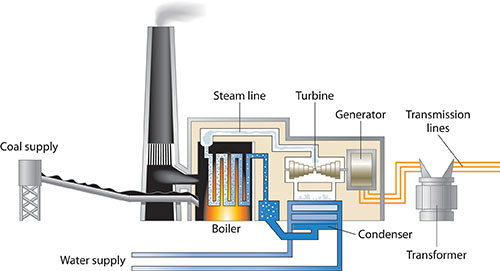
Credit: Principles of General Chemistry(link is external)Creative Commons BY-NC-SA 3.0
Feeding Units
This is the front end of the plant. The materials that will be fed to the plant must be made into small particles in order to increase the surface area; for coal, it must be crushed to a certain size (less than 100 micrometers). We will discuss biomass preparation when we get to the discussion on the combustion of biomass. The front end of the coal delivery system includes a coal hopper (like a funnel in some ways) and a conveyor belt. Coal is typically sprayed into the boiler with air for better mixing of the two reactants.
Plant Boiler
The boiler has what is called a water wall inside - the water wall is a series of tubes welded together where the water flows. The "box" around the tubes is the boiler itself and is typically 10-20 stories high. The coal and air are sprayed into multiple burners. Figure 3.6a is an example of the water tubes inside a boiler, and Figure 3.6b shows the large scale of a boiler unit.
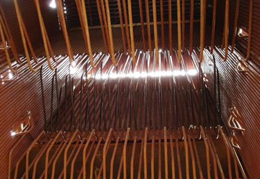
Credit: State of Delaware
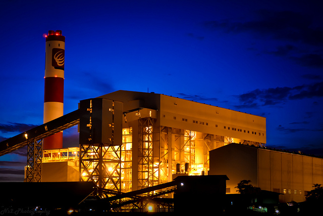
Credit: e . mercado via flickr CC BY 2.0
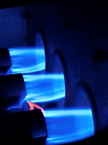
Burners Inside Boiler
There are typically multiple burners along the bottom of the boiler. It is a way to increase the area of heat being generated.
Credit: University of Salford Press Office via flickr CC BY 2.0
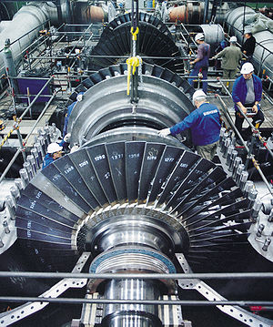
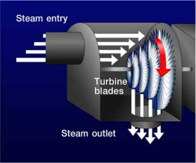
Plant Turbines
In a coal-fired power plant, the turbines are significantly more sophisticated than the turbine we saw for a waterwheel or for wind. Figure 3.8a shows the turbine - it actually has multiple stages on it in order to increase the efficiency.
Credit: Turbine: from Wikipedia.org
Credit: Geothermal Education Office
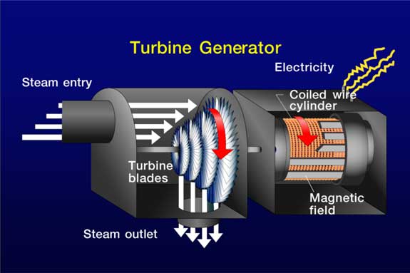
Plant Generators
In order to generate electricity, the turbine is connected to a generator. A generator is a device of coiled wires that turn around a magnet - the action of the wires turning around the magnet generates electricity. Figure 3.9a shows the turbine in the previous figure connected to a generator, and Figure 3.9b shows the inside of the power plant generator and the enormous size that it is.
Credit: Geothermal Education Office
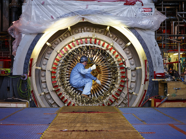
Credit: cleveland.com
Interaction of Condenser and Cooling Water Facilities
Steam exits the turbine and is condensed back to water. Typically the condenser is a heat exchanger that uses a natural water source as working fluid. Many power plants are located along rivers or on lakes in order to have a place to return and reuse water. Condensate is returned to the boiler. Water must be extremely pure in order to avoid corrosion in boiler tubes and/or turbine blades; the purity standards may be stricter than for drinking water.
The condenser heat is transferred from the steam (including heat & condensation) to condenser water; therefore, the water leaving the condenser will be hot or warm. If the water is dumped directly into a water source while hot, it will alter the microclimate and local ecology. This is called thermal pollution. Often, cooling towers are used to cool condenser effluent before returning it to the water source. Figure 3.10a shows a schematic of how the condenser interacts with a reservoir and cooling tower, and Figure 3.10b is a picture of a cooling tower at a power plant.
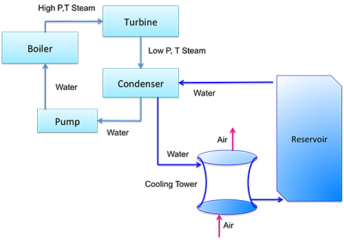
Credit: Dr. Caroline B. Clifford
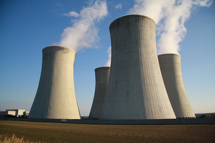
Credit: Jiří Sedláček, Wikimedia Commons