
8.4: Natural Gas and Synthetic Natural Gas as Feedstocks for Liquid Fuels
- Page ID
- 48595

8.4 Natural Gas and Synthetic Natural Gas as Feedstocks for Liquid Fuels
In Lesson 4, we discussed gasification in depth. We also briefly discussed using syngas to make liquids. In Lesson 8, we will go into a little more depth. These types of processes are called indirect liquefaction.
The primary objective of gasification is to produce a syngas primarily composed of carbon monoxide (CO) and hydrogen (H2). After gasification, the product needs to be cleaned to remove any liquids, and there are several reactions that can be done to change the H2/CO ratio or to make different products. This is where we will start this lesson.
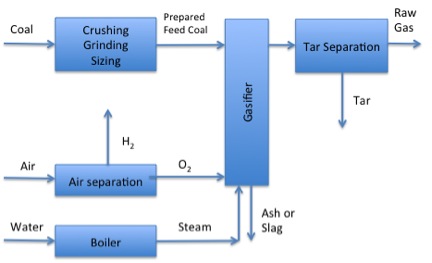
Figure 8.8 (a, b and c) shows the three different process phases that the gas must go through. The first phase (Figure 8a) is the gasifier and separation of gas, liquid, and solid products. The biomass is not pure carbon, and all the streams will contain a variety of other compounds that may not be wanted or may be harmful.
Solids are removed by a cyclone or an electrostatic precipitator. The particles are similar to what is seen in combustion – ungasified or partially gasified particles. Some mineral matter/ash can also be in the solids. A separator is used to remove the liquids, mainly tars and water that must be separated and processed for use. The water fraction can be used to react the organic compounds further, and the tars can be distilled and reacted further similar to the direct liquefaction processes we described in previous sections. In any case, the water must be treated before disposal.
- Click here for a text alternative of Figure 8.8a
-
Phase 1 of Gasification:
Coal is crushed, ground and sized in the presence of hydrogen. Next the prepared feed coal goes into the gasified where there is steam from a boiler and lots of oxygen gas. Ash and slag are removed, and the remaining products go into tar separation where the raw gas is separated from the tar.
Credit: Dr. Caroline B. Clifford
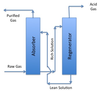
The gases can also contain unwanted gases. Three gases that need to be removed from the gas phase are ammonia (NH3), carbon dioxide (CO2), and hydrogen sulfide (H2S). They are corrosive and/or toxic and need to be removed. The acid gases (H2S and CO2) are called acid gases because they can dissolve in water and produce weak acids that can be corrosive to metals. There is a range of processes that can separate out the acid gases. One typical method to remove these harmful gases is called the Rectisol process (Figure 8.8b). Both H2S and CO2 are soluble in methanol, while H2 and CO are not. In the simplified schematic in Figure 8.10b, there are two parts to the process, an absorber, and a regenerator. The raw gas goes into the absorber and comes into contact with the lean solution of methanol. The purified gas goes out the top, and the solution rich in unwanted absorbed gases goes to the regenerator – the acid gases are then separated out from the methanol so that a lean methanol solution comes out the bottom to be recycled for use in the absorber. The H2S in the acid gas can be burned or reacted with SO2 to form solid sulfur, which is used for making chemicals. The CO2 goes out the stack but could also be captured if processes to capture it are put into place.
- Click here for a text alternative of Figure 8.8b
-
Phase 2 of Gasification:
Raw Gas from phase one enters the absorber and the purified gas is removed. Then the remaining rich solution goes into the regenerator. Acid gas is separated in the regenerator and the remaining lean solution returns to the absorber
Credit: Dr. Caroline B. Clifford
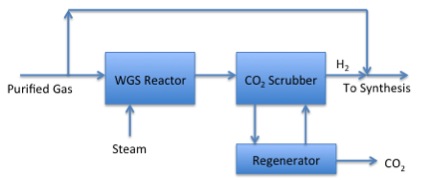
The H2/CO ratio may not be ideal for downstream synthesis reactions. Figure 8.8c shows a process to use the water-gas shift reaction to change the ratio of H2/CO.
- Click here for a text alternative of Figure 8.8c
-
Phase 3 of Gasification:
The purified gas and steam go to a WHS reactor. From there they enter a CO2 scrubber which can send the gas to the regenerator to remove additional CO2 after that the gas can return to the scrubber and with hydrogen gas proceed to synthesis.
Credit: Dr. Caroline B. Clifford
Ideally, the gas stream coming off the gasifier followed by a Rectisol unit could be reasonably pure H2 and CO. The water-gas shift can change the ratio of H2/CO. The reaction is shown below:
CO + H2O←→CO2 + H2
This would be the way to make less CO and more H2, but the reaction can go in reverse to make more CO and less H2 as well. From coal gasification, we want to shift it to the right as written. Advantages include:
- that it's an equilibrium process;
- can shift reaction other direction by taking advantage of LeChatlier’s Principle;
- with the same number of moles on both sides, the equilibrium position is independent of pressure – no requirement of compression or release of pressure of shift reactor;
- can be adapted to any operating pressure.
The major disadvantage of the water-gas shift reaction is it’s a CO2 factory! There only a few ways of separating CO2, such as a monoethylamine (MEA) scrubber. You can separate the CO2 to a 99% concentration, which would be ideal for CCS. Another thing to consider is we do not need to separate the entire gas stream and shift it; we only need to do enough to get the H2/CO ratio where we want it to be. Once we get to this point, we can be ready to do some synthesis of liquids.