
1.2: Biogas Energy from Organic Wastes
- Page ID
- 46839

Hamed El Mashad
Biological and Agricultural Engineering Department
University of California, Davis
Davis, CA, USA
and
Agricultural Engineering Department
Mansoura University
El Mansoura, Egypt
Ruihong Zhang
Biological and Agricultural Engineering Department
University of California, Davis
Davis, CA, USA
| Key Terms |
| Anaerobic digesters | Suspended growth | Sizing |
| Biochemical and physical processes | Biogas cleaning | Yield estimation |
| Fixed growth | Biogas upgrading | Commercial uses |
Variables
Introduction
Fossil fuel is currently the main energy source in the world. With its limited supplies and the environmental pollution caused by its use, there is a need to increase the use of renewable energy. Sources of renewable energy include the sun, winds, tides, waves, rain, geothermal heat, and biomass. Biomass is plant or animal material that can be used to produce bioenergy as heat or fuel. The technologies for converting biomass into bioenergy can be classified as biochemical, physicochemical, and thermal-chemical technologies. The main biochemical technologies include anaerobic digestion to produce biogas and fermentation to produce alcohols such as ethanol and butanol. The main physicochemical technology is transesterification to produce biodiesel, and the main thermal-chemical technologies are combustion to produce heat, torrefaction to produce solid fuels, pyrolysis to produce oil, and gasification to produce syngas. The selection of a specific technology depends on the composition of the available biomass as well as the desired bioenergy considering economics, social implications, and environmental impact.
Biogas energy is produced by anaerobic digestion of organic matter, which is carried out by a consortium of microorganisms in the absence of oxygen. Airtight vessels called digesters or reactors are used for the process. Biogas is a mixture of methane (CH4), carbon dioxide (CO2), and traces of other gases, such as ammonia (NH3) and hydrogen sulfide (H2S). Anaerobic digestion technology can be used to treat organic materials, such as food residues and wastewater, thus reducing the amount of material to be disposed of, while generating bioenergy.
This chapter introduces biogas production using anaerobic digestion of organic waste (e.g., food scraps, animal manure, grass clippings and straws). It introduces the processes involved in anaerobic digestion, the major factors that influence these processes, the biogas produced, and common types of digesters. It also presents methods for determining biogas and methane yields.
Outcomes
After reading this chapter, you should be able to:
- • Explain the microbiological, chemical, and physical processes in anaerobic digestion
- • Describe the types of anaerobic digester used for biogas production and factors influencing their performance
- • Describe some methods of cleaning biogas for energy generation
- • Estimate the quantity of biogas, methane, and energy that can be produced from an organic material
- • Calculate the volume of a digester to treat a certain amount of a substrate
Concepts
Anaerobic digestion is a bioconversion process that is carried out by anaerobic microorganisms including anaerobic bacteria and methanogenic archaea to break down and convert organic matter into biogas, which is mainly a mixture of CH4 and CO2.
Biochemical Processes
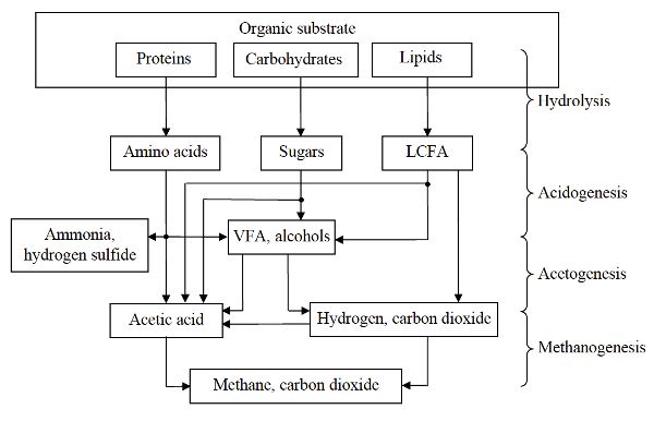
Anaerobic digestion involves four major biochemical processes: hydrolysis, acidogenesis, acetogenesis, and methanogenesis. Figure \(\PageIndex{1}\) shows these processes for the conversion of organic substrates (such as proteins, carbohydrates, and lipids) into biogas.
Hydrolysis converts complex organic matter using extracellular and intracellular enzymes from the microorganisms to monomer or dimeric components, such as amino acids, single sugars, and long chain fatty acids (LCFA). During acidogenesis, the hydrolysis products are converted by acidogenic bacteria into smaller molecules such as volatile fatty acids (VFA), alcohols, hydrogen, and NH3. In acetogenesis, alcohols and VFA (other than acetate) are converted to acetic acid or hydrogen and CO2. The acidogenic and acetogenic bacteria are a diverse group of both facultative and obligate anaerobic microbes including Clostridium, Peptococcus, Bifidobacterium, Corynebacterium, Lactobacillus, Actinomyces, Staphylococcus, Streptococcus, Desulfomonas, Pseudomonas, Selemonas, Micrococcus, and Escherichia coli (Kosaric and Blaszczyk, 1992). During methanogenesis, acetic acid and methanol (an alcohol) are converted to CH4 and CO2. In addition, CO2 and hydrogen are converted into CH4. Methanogenic archaea include a diverse group of obligate anaerobes such as Methanobacterium formicicum, Methanobrevibacter ruminantium, Methanococcus vannielli, Methanomicrobium mobile, Methanogenium cariaci, Methanospirilum hungatei, and Methanosarcina barkei (Kosaric and Blaszczyk, 1992). Examples of the conversion of selected compounds during anaerobic digestion are shown in Table \(\PageIndex{1}\).
| Sub-processes | Examples |
|---|---|
|
Hydrolysis |
Conversion of carbohydrates and proteins: \( \text { Cellulose }+\mathrm{H}_{2} \mathrm{O} \rightarrow \text { sugars } \) \( \text { Proteins }+\mathrm{H}_{2} \mathrm{O} \rightarrow \text { amino acids } \) |
|
Acidogenesis |
Conversion of glucose into acetic and propionic acids: \( \mathrm{C}_{6} \mathrm{H}_{12} \mathrm{O}_{6} \rightarrow 3 \mathrm{CH}_{3} \mathrm{COOH} \) \( \mathrm{C}_{6} \mathrm{H}_{12} \mathrm{O}_{6}+2 \mathrm{H}_{2} \rightarrow 2 \mathrm{CH}_{3} \mathrm{CH}_{2} \mathrm{COOH}+2 \mathrm{H}_{2} \mathrm{O} \) |
|
Acetogenesis |
Conversion of propionate and butyrate into acetate and hydrogen as follows: \( \mathrm{CH}_{3} \mathrm{CH}_{2} \mathrm{COO}^{-}+3 \mathrm{H}_{2} \mathrm{O} \rightarrow \mathrm{CH}_{3} \mathrm{COO}^{-}+\mathrm{HCO}_{3}^{-}+\mathrm{H}^{+}+3 \mathrm{H}_{2} \) \( \mathrm{CH}_{3} \mathrm{CH}_{2} \mathrm{CH}_{2} \mathrm{COO}^{-}+2 \mathrm{H}_{2} \mathrm{O} \rightarrow 2 \mathrm{CH}_{3} \mathrm{COO}^{-}+\mathrm{H}^{+}+2 \mathrm{H}_{2} \) \( 4 \mathrm{H}_{2}+2 \mathrm{HCO}_{3}^{-}+\mathrm{H}^{+} \rightarrow \mathrm{CH}_{3} \mathrm{COO}^{-}+4 \mathrm{H}_{2} \mathrm{O} \) |
|
Methanogenesis |
Conversion of acetic acid, carbon dioxide and hydrogen, and methanol to methane: \( 4 \mathrm{CH}_{3} \mathrm{COOH} \rightarrow 4 \mathrm{CO}_{2}+4 \mathrm{CH}_{4} \) \( \mathrm{CO}_{2}+4 \mathrm{H}_{2} \rightarrow \mathrm{CH}_{4}+2 \mathrm{H}_{2} \mathrm{O} \) \( 4 \mathrm{CH}_{3} \mathrm{OH}+6 \mathrm{H}_{2} \rightarrow 3 \mathrm{CH}_{4}+2 \mathrm{H}_{2} \mathrm{O} \) |
Types of Anaerobic Digesters
Anaerobic digesters can be categorized based on how the microorganisms inside the digester interact with the substrate. There are three attributes used: (1) how the microorganisms are grown: suspended growth or fixed growth, (2) the feeding of substrate into the vessel as a batch, a plug, or continuously and (3) the number of stages, single or multistage. Further design considerations are whether the contents are actively mixed, whether the orientation is predominantly vertical or horizontal, and whether the flow through the vessel is downwards or upwards.
Suspended Growth Anaerobic Digesters
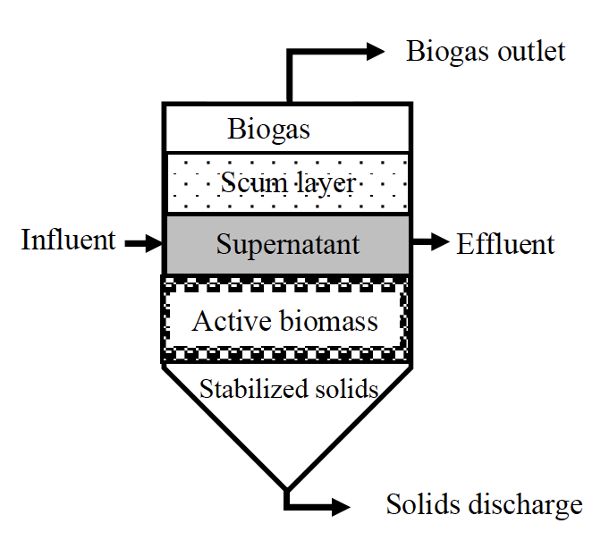
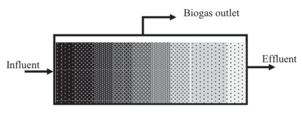
Suspended growth digesters are usually used for substrates with a high content of suspended solids, such as municipal wastewater and diluted solid waste. They can be operated as a batch process (Figure \(\PageIndex{2}\)) or as plug flow (Figure \(\PageIndex{3}\)), where a batch of substrate moves through the vessel as a block of material, called a plug. The microorganisms are dispersed throughout the reactor when the digester contents are mixed, such as continuous stirred tank reactors (CSTR), or anaerobic contact reactor (ACR) which is a CSTR with effluent solids recycled from a settling tank for solids. In a CSTR, solid retention time (SRT) equals the hydraulic retention time (HRT), which is the average time the solids and liquid remain in the bioreactor vessel. CSTR systems are operated at HRT and SRT ranging from 10 to 30 days. The ACR has a longer SRT (>50 days) than the HRT (0.5–5 days) because part of effluent solids is recycled back into the digester.
Figure \(\PageIndex{2}\) shows a schematic of a suspended growth batch anaerobic digester. These are simple to design and operate. They are usually an air-tight vessel with inflow and outflow ports to supply fresh substrate and remove spent substrate, a biogas outlet port, and a port for removing solids. These systems are commonly deployed at small scale and for testing the anaerobic biodegradability of different materials. Operation starts with mixing a fixed amount of substrate with inoculum, which is active bacterial culture taken directly from a running reactor. Afterwards, anaerobic conditions are maintained for the digestion time (i.e., the retention time), which should ensure the depletion of all the available substrate.
The CSTR is typically used to treat agricultural and municipal wastes with total solid (TS) contents of 3% to 12%. They are usually operated at controlled temperatures, so the vessel, constructed either below or above ground, is equipped with a heating system and thermal insulation to maintain a constant internal temperature. Plug flow digesters (Figure \(\PageIndex{3}\)) are constructed as long pipes or channels, above or below ground, with a gas tight cover. The digester contents travel through the vessel where they are converted into biogas until reaching the outlet. The residence time is determined by the time elapsed between the feed of fresh substrate and discharge of the digested materials. They are used to treat relatively high TS of 12% to 16%.
Covered lagoons are commonly used to treat wastewater with low solids content (<3%), such as flushed animal manure. Manure lagoons on livestock farms can be upgraded to be anaerobic covered lagoons using a non-permeable covering to collect the biogas and double synthetic liners to prevent ground water contamination by seepage of the digester content. Covered lagoon digesters can be mixed or non-mixed (i.e., have mechanical agitation or not) and can be operated as plug flow or CSTR systems. They usually operate at ambient temperatures dictated by the local climate.
There is also a class of suspended growth systems called high rate systems, which are characterized by using longer SRT than HRT. These systems are usually used for diluted wastewater with an SRT of >20 days, which is achieved by retaining the microorganisms in the digester. The long SRT enables treatment at high organic loading rates (amount of organic material processed per unit time). HRT can range from hours to days, depending on the characteristics of the wastewater. Designs include anaerobic sludge bed reactors (ASBR) and upflow sludge blanket reactors (UASB). In the ASBR, the retention of microorganisms is achieved by solids settling in the reactor prior to effluent removal. In the UASB, microorganisms form granules and are retained in the reactor.
Fixed Growth Anaerobic Digesters
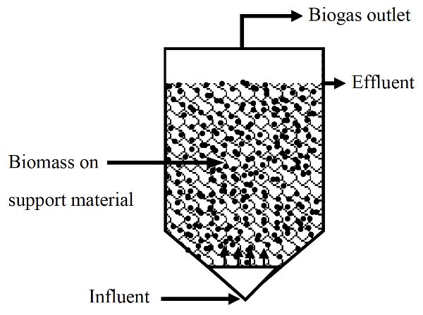
In fixed growth digesters, microorganisms are grown on solid media allowing SRT longer than HRT. These systems are also high rate systems. Fixed growth anaerobic digesters are used to treat soluble organic wastes (i.e., low suspended solids content) that do not require hydrolysis. Media, such as plastic or rocks, are usually used to support the attachment and growth of microorganisms, which form biofilms. As wastewater passes over the growth media, contaminants are absorbed and adsorbed by the biofilms and degraded. Therefore, these digesters can be operated at higher organic loading rates than the suspended growth digesters.
Anaerobic filters are a type of fixed-growth anaerobic digester (Figure \(\PageIndex{4}\)). In these systems, much of the sludge containing active microorganisms is retained inside the digester by being attached as a biofilm to a solid (inert) carrier material. Anaerobic filters are operated in up-flow mode, meaning the inflow is below the outlet in the digestion chamber.
Factors Affecting Anaerobic Digestion and Biogas Production
Anaerobic digestion processes are affected by many factors, including substrate composition, temperature, pH, organic loading, retention time, and mixing, which in turn affect the yield and rate of biogas production. Process stability (i.e., the consistency of the biogas production rate) depends on maintenance of the biochemical balance between the acidogenic and methanogenic microorganisms. Process stability also depends on the chemical composition and physical properties of the substrate, digester configuration, and process parameters such as temperature, pH, and NH3 concentration.
Substrate Composition and Characteristics
Substrate composition, particularly physical and chemical characteristics, is an important factor affecting design of biomass handling and digestion systems, performance of anaerobic digestion, biogas yield, and downstream processing of the digested materials. Materials with large particle sizes (e.g., crop residues and energy crops) may need to be ground before being fed into the anaerobic digester. The grinding process can aid in the conversion process because small particles can be degraded faster than large ones. Moreover, grinding can help when handling the substrate and mixing the digester contents. Mixed wastes, such as municipal solid waste, usually contain inorganic materials (e.g., metals and construction debris) and need a separation process to remove these inorganic materials. Organic matter is mainly composed of carbon (C), hydrogen (H), and oxygen (O). It also contains many nutrient elements including macronutrients (e.g., nitrogen (N), potassium, magnesium, and phosphorus) and micronutrients (zinc, manganese, cobalt, nickel, and copper). Example compositions are given in Table 1.2.2. All these nutrients are needed by microorganisms in order to break down and convert organic matter into biogas. An appropriate C: N ratio in the substrate is in the range of 20–25 C to 1 N. Most organic wastes, such as animal manure and food waste, contain enough nutrients to support the growth of microorganisms.
The organic matter content of a substrate is described in terms of volatile solids (VS), chemical oxygen demand (COD), or biochemical oxygen demand (BOD). VS are used to characterize substrates with a high solids content, while COD and BOD are used to characterize substrates that have a low solids content, such as wastewater. VS is the organic fraction of total solids (TS) or dry matter. BOD is used to describe the biodegradability of a substrate, while COD is the amount of oxygen needed to chemically oxidize the organic matter in a substrate. If the chemical composition of a substrate is known, the COD can be calculated using the chemical reaction:
\( \mathrm{C}_{\mathrm{a}} \mathrm{H}_{\mathrm{b}} \mathrm{O}_{\mathrm{c}} \mathrm{N}_{\mathrm{d}}+\left(a+\frac{b}{4}-\frac{c}{2}-\frac{3 d}{4}\right) \mathrm{O}_{2} \rightarrow a \mathrm{CO}_{2}+\left(\frac{b}{2}-\frac{3 d}{2}\right) \mathrm{H}_{2} \mathrm{O}+d \mathrm{NH}_{3} \)
where a, b, c, and d are number of atoms of carbon, hydrogen, oxygen, and nitrogen, respectively, and allow calculation of the amount of oxygen required for the reaction, i.e.,
\( \left[\left(a+\frac{b}{4}-\frac{c}{2}-\frac{3 d}{4}\right) \mathrm{O}_{2}\right]=\mathrm{COD} \).
| Sample | C/N | C (%) |
N (%) |
P (%) |
K (%) |
S (%) |
Ca (%) |
Mg (%) |
B (ppm) |
Zn (ppm) |
Mn (ppm) |
Fe (ppm) |
Cu (ppm) |
Na (ppm) |
Co (ppm) |
Ni (ppm) |
|---|---|---|---|---|---|---|---|---|---|---|---|---|---|---|---|---|
|
Tomato waste |
13.0 |
40.3 |
3.1 |
0.3 |
1.1 |
0.3 |
2.4 |
0.7 |
72.9 |
40.1 |
183.6 |
4482.8 |
23.6 |
1528.5 |
2.5 |
14.0 |
|
Tomato pomace |
17.0 |
57.8 |
3.5 |
0.5 |
1.0 |
0.2 |
0.3 |
0.3 |
17.6 |
40.1 |
53.8 |
510.3 |
14.3 |
477.0 |
0.4 |
3.0 |
|
Rice straw |
77.0 |
38.6 |
0.5 |
0.1 |
2.8 |
0.1 |
0.2 |
0.2 |
6.6 |
33.5 |
492.2 |
432.2 |
4.9 |
2054.0 |
1.3 |
2.0 |
|
Egg liquid waste |
8.0 |
61.8 |
7.8 |
0.6 |
0.7 |
0.7 |
0.4 |
0.1 |
1.3 |
18.1 |
1.5 |
68.0 |
15.9 |
7165.0 |
<0.1 |
5.0 |
|
Commercial food waste |
16.0 |
43.7 |
2.7 |
0.5 |
2.4 |
0.3 |
3.5 |
0.2 |
18.7 |
170.8 |
34.1 |
443.7 |
9.1 |
3443.0 |
0.4 |
2.0 |
|
Supermarket vegetable waste |
22.0 |
45.6 |
2.1 |
0.4 |
2.9 |
0.2 |
0.3 |
0.2 |
38.6 |
126.6 |
22.0 |
187.1 |
10.4 |
1669.5 |
0.2 |
15.0 |
|
Cardboard |
231.0 |
46.2 |
0.2 |
0.0 |
0.0 |
0.2 |
0.4 |
0.0 |
42.4 |
18.6 |
26.3 |
255.8 |
10.3 |
1950.5 |
0.3 |
3.0 |
|
Dairy manure |
18.0 |
34.0 |
1.9 |
0.8 |
2.6 |
0.5 |
1.5 |
1.5 |
70.0 |
280.0 |
210.0 |
2100 |
110.0 |
7790 |
<20 |
|
|
Chicken manure |
9.0 |
31.9 |
3.7 |
1.8 |
2.8 |
0.6 |
10.3 |
0.6 |
34.6 |
325.3 |
312.2 |
739.4 |
36.1 |
4162.0 |
0.5 |
12.0 |
Temperature
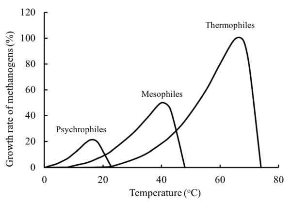
Temperature is an important factor affecting the performance of anaerobic digestion because it affects the kinetics of the processes. Microorganisms are usually classified by the optimum temperature and the temperature range at which they grow. The normal classification is psychrophilic (<25°C), mesophilic (25 to 45°C), and thermophilic (45 to 65°C), but in theory there is the extreme of hyperthermophilic anaerobic archaea and bacteria that can grow in geothermal environments with optimal growth temperatures of 80°C to 110°C (Stetter, 1996). Thermophilic digestion may produce biogas with a higher CO2 content than mesophilic digestion due to the low solubility of CO2 in water at high temperatures.
The growth rate of microorganisms increases with increasing temperature up to an optimum. Above the optimum temperature, growth declines due to the thermal denaturation of the cell protein. The growth will cease when the essential protein of the cell is destroyed. Figure 1.2.5 shows the relative growth rate of methanogens at different temperature ranges. Within the temperature range of one species, the growth rate exponentially increases with temperature. Thermodynamically, most biochemical reactions require less energy to proceed at high temperatures. The rate of most chemical reactions approximately doubles with a temperature increase of 10°C (Stanier et al., 1972). The energy required to heat up the substrate and to keep the digester at the desired temperature is greater at higher temperatures.
pH
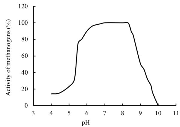
The pH of a digester is affected by the interaction between the composition of the substrate, its buffering capacity, and the balance between the rates of acidification and methanogenesis. If the rate of methanogenesis is lower than acidogenesis, the pH might reach values below 6, which can cause inhibition to methanogenic archaea. The relationship between pH and methanogenic activity is a bell shaped curve (Figure \(\PageIndex{6}\)) with a maximum methanogenic activity at pH values between about 6.8 and 8 (Speece, 1996; Khanal, 2008). An optimum pH near neutrality should be maintained in the anaerobic digester for biogas production.
Organic Loading
Organic loading (or initial loading) is a measure of the amount of organic matter, expressed in terms of the amount of VS or COD that enters a batch digester at the beginning of a process cycle. It is an important parameter that affects digester sizing because it determines the concentration of functional microbial biomass per unit mass of substrate. For continuously fed digesters, organic loading rate (OLR), usually defined as the amount of organic matter fed per unit volume of the digester per day, depends on the biodegradation kinetics of the substrate, digester design and operating conditions. For example, a CSTR treating animal manure with a TS content of 1–6% is usually operated at an OLR of 1.6 to 4.8 kg m3 day−1 and an HRT of 15 to 30 days.
Retention Time
Retention time is the time for the substrate to remain in the digester to be processed by the microorganisms. The appropriate retention time depends on the chemical and physical characteristics of the substrate and the rate of microbial metabolism. Complex substrates, such as agricultural wastes (e.g., animal manure), usually have low biodegradation rates and so need longer retention times (20–30 days), while highly biodegradable materials, such as food waste, may need shorter retention times (<15 days) to convert the biodegradable organic matter into biogas.
Mixing
Mixing affects the performance of anaerobic digesters by ensuring homogenization of the reactor contents by breaking of the substrate particles and exposing large surface areas of the substrate to microorganisms. Adequate mixing prevents development of stratification inside digesters, which could result in unfavorable micro-environments for the methanogens, such as regions rich in toxic compounds or with low pH. Mixing also helps to maintain a uniform temperature in the digester and prevents the formation of a scum layer. The requirement to achieve proper mixing depends on the digester shape, type of mixing systems, and solids content inside the digester. For example, a rectangular tank poses difficulty for mixing compared to cylindrical and egg-shaped reactors because it is difficult to mix into the corners. Digesters can be mixed with mechanical mixers, recirculation of biogas, or recirculation of reactor contents. The selection of the mixing system depends on the density of substrate (i.e., solid concentration), required mixing intensity, homogeneity, availability and cost of mixing equipment, and maintenance and energy consumption costs.
Process Configuration
Anaerobic digestion processes can be carried out in single stage digesters or in multistage digesters. Single stage digesters are usually used for materials that have balanced degradation rates of hydrolysis, acidogenesis, and methanogenesis and have enough buffer capacity to maintain the pH of the digester around neutral. However, for highly biodegradable materials, such as food waste, multiple stage (mostly two stages) digestion systems are usually used. In these systems, hydrolysis and acidogenesis are the predominant processes in the first stage, with low pH (4–6) due to the high concentrations of VFA. The biogas produced from the first stage contains high contents of CO2 and hydrogen and low content of CH4. In the second stage, methanogenesis predominates when VFA are consumed by the methanogenic archaea and the pH is in the range of 6.8–8. The biogas produced from the second stage has high CH4 content (50–70%).
Ammonia Concentration
The anaerobic digestion of protein-rich substrates may produce high NH3 concentrations that can cause inhibition or even toxicity to anaerobic microorganisms. Microorganisms need N for their cell synthesis. Approximately 6.5% of the influent N is used for cell production. Fermentative bacteria can usually utilize both amino acids and NH3, but methanogenic bacteria only use NH3 for the synthesis of bacteria cells (Hobson and Richardson, 1983). High NH3 concentrations can cause inhibition, or even toxicity, to methanogenic microorganisms. Inhibition is indicated by a decrease in NH3 production and increasing VFA concentrations. When there is a total cessation of the methanogenic activity, free NH3 is usually the main cause. This is because microorganism cells are more permeable to free NH3 than to ammonium ions. The concentration of free NH3 depends on the total NH3, temperature, and pH.
Estimation of Biogas and Methane Yields
Theoretical Estimation of Yield
Biogas and CH4 yields can be estimated theoretically from the chemical composition of the substrate or measured using batch digestion experiments. Biogas and CH4 yield from a completely biodegradable organic substrate with the composition (CaHbOcNd) can be determined using Buswell’s equation (Buswell and Mueller, 1952):
\( \mathrm{C}_{\mathrm{a}} \mathrm{H}_{\mathrm{b}} \mathrm{O}_{\mathrm{c}} \mathrm{N}_{\mathrm{d}}+\left(\frac{4 a-b-2 c+3 d}{4}\right) \mathrm{H}_{2} \mathrm{O} \rightarrow\left(\frac{4 a+b-2 c-3 d}{8}\right) \mathrm{CH}_{4}+\left(\frac{4 a-b+2 c+3 d}{8}\right) \mathrm{CO}_{2}+d \mathrm{NH}_{3} \)
This equation does not consider the needs of organic matter for cell maintenance and anabolism. From Buswell’s equation, the total amount of biogas produced from one mole of the biodegradable organic substrate can be calculated as a summation of CH4 and CO2, i.e.:
\( \left[\left(\frac{4 a+b-2 c-3 d}{8}\right)+\left(\frac{4 a-b+2 c+3 d}{8}\right)\right] \)
The volume of the biogas or methane yield per each gram of the substrate L g−1 [VS] can be calculated using the molar volume of an ideal gas as 22.4 L at the standard temperature and pressure as:
\[ M_{\mathrm{y}}=\frac{\left(\frac{4 a+b-2 c-3 d}{8}\right) \times 22.4}{12 a+b+16 c+14 d} \]
where My = methane content in the biogas, % (mole/mole or v/v).
Assuming that biogas is composed mainly of methane and carbon dioxide and ammonia production is insignificant, methane content in the biogas can be calculated as follows:
\[ M_{\mathrm{C}}=\frac{\left(\frac{4 a+b-2 c-3 d}{8}\right) \times 100}{\left(\frac{4 a+b-2 c-3 d}{8}\right)+\left(\frac{4 a-b+2 c+3 d}{8}\right)} \]
where Mc = methane content in the biogas, % (mole/mole or v/v).
The CH4 production after a long degradation time is called the methane potential. Methane yield can be expressed as the volume of gas produced per unit mass of the substrate (L [CH4]/kg [substrate]), VS (L [CH4]/kg [VS]) or COD (L [CH4]/kg [COD]). Theoretical CH4 yield and content of selected substrates computed using the Buswell equation (Table 1.2.3) are usually underestimated because CO2 is more soluble in water than CH4. In anaerobic digesters, CH4 content of the biogas ranges from 55% to 70%, depending on the substrate and operation conditions of digesters (Table 1.2.3). Substrates rich in lipids should produce biogas rich in methane.
| Substrate Type | Formula | Gas Yield[a] (L g−1 [VS]) | Methane Content[b] (%) | ||
|---|---|---|---|---|---|
| CH4 | CO2 | NH3 | |||
|
Carbohydrate |
(C6H10O5)n |
0.415 |
0.415 |
0.000 |
50.0 |
|
Protein |
C5H7NO2 |
0.496 |
0.496 |
0.198 |
50.0 |
|
Lipid |
C57H104O6 |
1.014 |
0.431 |
0.000 |
70.2 |
|
Acetate |
C2H4O2 |
0.374 |
0.374 |
0.000 |
50.0 |
|
Ethanol |
C2H6O |
0.731 |
0.244 |
0.000 |
75.0 |
|
Propionate |
C3H6O2 |
0.530 |
0.379 |
0.000 |
58.3 |
|
[a] Yields are at standard temperature and pressure (see text). [b] Assuming the biogas is composed of methane and carbon dioxide. |
|||||
Modeling the Anaerobic Digestion Process to Estimate Yield
There are mechanistic models that describe the anaerobic digestion process, which can be used to predict the performance of anaerobic digesters. One of the most used is the Anaerobic Digestion Model No. 1 (ADM1), developed by the International Water Association Task Group for Mathematical Modelling of Anaerobic Digestion Process (Batstone et al., 2002). ADM1 is structured around biochemical sub-processes, including hydrolysis, acidogenesis, acetogenesis, and methanogenesis. While a mechanistic modelling approach is necessary for advanced design, a simple first-order kinetic model can be used to calculate the methane yield from different substrates, such as food waste, animal manure, and crop residues, and be used for preliminary design. The first-order kinetics for a batch digester can be written as:
\[ \frac{d S}{\mathrm{dt}}=-k S \]
where t = digestion time (days)
k = first-order degradation kinetic rate constant (day−1)
S = concentration of the biodegradable organic matter (expressed as VS, COD, or BOD) in the digester (kg m−3)
With the concentration of the biodegradable substrate at the beginning of the digestion time designated as S0 (kg m−3), the equation can be expressed as:
\[ S=S_{0} \mathrm{e}^{-\mathrm{kt}} \]
Equation 1.2.4 can be used to predict the remaining substrate concentration (S) in the digester after a period of digestion time (t) if the initial substrate concentration (S0) and degradation kinetic rate constant are known. The amount of degraded organic matter that is converted into methane, and the amount of methane produced can be calculated as:
\[ S_{\mathrm{deg}}=V_{\mathrm{w}}\left(S_{0}-S\right) \]
\[ M_{\mathrm{p}}=M_{\mathrm{y}} S_{\mathrm{deg}} \]
where Sdeg = degraded organic matter in the digester (kg)
Vw = working volume of digester (i.e., volume of liquid inside the digester) (m3)
Mp = amount of methane produced (m3)
My = methane yield (m3 kg−1)
Equations 1.2.4, 1.2.5 and 1.2.6 can be used to fit experimental data describing the substrate concentration at time steps throughout the process to determine the first-order degradation kinetic rate constant. They can also be used to predict degraded organic matter in the digester and methane yield at different digestion times if the first-order degradation kinetic rate constant is known from the literature or from experiments.
Estimation of Energy Production from a Substrate
The amount of energy contained in a fuel (e.g., biogas) is expressed using the higher heating value (HHV) or lower heating value (LHV). The HHV is the total heat produced from a complete combustion of a unit (usually 1 m3) of the gas under a constant pressure and all the water formed by the combustion reaction condensed to the liquid state. The LHV is the net caloric value produced from the combustion of a unit amount of the fuel and all the water formed during the combustion reaction remains in the vapor state. Methane is used to calculate the amount of energy contained in the biogas because it is the main combustible gas. At standard temperature and pressure, methane has a LHV of approximately 36 MJ m−3. Therefore, the LHV of biogas containing 65% methane is approximately 23.4 MJ m−3, which is calculated by multiplying the LHV of methane with the methane content of the biogas.
The amount of energy that is produced from an anaerobic digester can be estimated using the amount of organic matter that is treated in a certain period of time (e.g., day), biogas yield of the substrate, and methane content of the biogas. Based on the TS and VS content of the substrate, the amount of organic matter to be treated can be calculated as:
\[ \phi_{\mathrm{om}}=Q \times T_{\mathrm{sc}} \times V_{\mathrm{sc}} \]
where ϕom = amount of organic matter to be treated per day, kg [VS] day−1
Q = amount of feedstock to be treated (kg day−1)
Tsc = total solids contents, %, wet basis
Vsc = volatile solids contents, % of Tsc
The daily biogas and methane production can be calculated as:
\[ B_{\mathrm{dp}}=\phi_{\mathrm{om}} B_{\mathrm{y}} \]
\[ M_{\mathrm{dp}}=B_{\mathrm{dp}} M_{\mathrm{C}} \]
where Bdp = daily biogas production, m3 day−1
By = biogas yield production, m3 kg−1 [VS]
Mdp = daily methane production, m3 day−1
Mc = methane content in the biogas, % vol vol−1
The daily energy production from biogas can be calculated as:
\[ E_{\mathrm{dp}}=B_{\mathrm{dp}} \times C_{\mathrm{vb}} \]
or
\[ E_{\mathrm{dp}}=M_{\mathrm{dp}} \times C_{\mathrm{vm}} \]
where Edp = daily energy production, MJ day−1
Cvb = calorific value of biogas, MJ m−3
Cvm = calorific value of methane, MJ m−3
Sizing Anaerobic Digesters
Anaerobic digester performance is controlled by the number of active microorganisms that are in contact with the substrate. Therefore, increasing the number of active bacteria can increase the conversion rate and, consequently, higher organic loading rates can be used. The total volume (Vt) of a digester is calculated from the working volume (Vw) and head space volume (Vh) as:
\[ V_{\mathrm{t}}=V_{\mathrm{w}}+V_{\mathrm{h}} \]
The head space volume is the gas volume above the liquid that is sometimes used for gas storage. The head space volume is usually about 10% of the working volume. The required working volume of a continuously fed anaerobic digester can be determined from the amount of organic matter (expressed as VS or COD) to be treated per day and the OLR:
\[ V_{\mathrm{w}}=\frac{\phi_{\mathrm{om}}}{\mathrm{OLR}} \]
where Vw = working volume of digester, m3
OLR = organic loading rate
The working volume can also be determined from the volume of waste to be treated per day and the hydraulic retention time of the digester:
\[ V_{\mathrm{w}}=V_{\mathrm{df}} \times \mathrm{HRT} \]
where Vdf = volumetric feed to the digester, m3 day−1
HRT = hydraulic retention time
Biogas Cleaning and Upgrading
Biogas cleaning and upgrading processes are important to remove harmful and undesired compounds and increase the quality of the biogas as a fuel. Biogas cleaning is the removal of impurities such as hydrogen sulfide and organic compounds, and upgrading is the removal of CO2 and water vapor, resulting in a relatively pure methane (biomethane) that can be used as automobile fuel or injected in a natural gas pipeline.
Table 1.2.4 shows a typical composition of biogas from agricultural waste digestion and municipal solid waste landfills.
Biogas Cleaning
Removing hydrogen sulfide is important prior to using biogas because it is corrosive and toxic. In the presence of water vapor, hydrogen sulfide forms sulfuric acid, which can cause serious corrosion of the metallic components of the digester and biogas handling equipment. The removal of hydrogen sulfide can be carried out using chemical precipitation by the addition of metal ions (usually ferric ions) to the digester vessel or chemical absorption by passing the biogas through a ferric solution (e.g., ferric choloride (known as an iron sponge)) as:
| Component | Agricultural Wastes | Municipal Solid Waste Landfills |
|---|---|---|
|
Methane |
50–80% |
45–65% |
|
Carbon dioxide |
30–50% |
34–55% |
|
Water vapor |
Saturated |
Saturated |
|
Hydrogen sulfide |
100–7,000 ppm |
0.5–100 ppm |
|
Hydrogen |
0–2% |
0–1% |
|
Ammonia |
50–100 ppm |
Trace |
|
Carbon monoxide |
0–1% |
Trace |
|
Nitrogen |
0–1% |
0–20% |
|
Oxygen |
0–1% |
0–5% |
|
Organic volatile compounds |
Trace |
5–100 ppm |
\( 3 \mathrm{H}_{2} \mathrm{~S}+2 \mathrm{FeCl}_{3} \rightarrow \mathrm{Fe}_{2} \mathrm{~S}_{3} \downarrow+6 \mathrm{H}^{+}+6 \mathrm{Cl} \)
In addition, hydrogen sulfide can be removed using biological oxidation by chemotrophic bacteria such as Thiobacillus thioparus. However, commercial application of biological oxidation is limited.
Siloxanes are volatile organic compounds that are usually found in the biogas produced from landfills. During combustion reactions, they are converted into silicon dioxide (SiO2) and microcrystalline quartz that deposit on engine parts, causing problems such as wearing. Activated carbon or silica gel are commonly used as adsorbents to remove these organic compounds from the biogas.
Biogas Upgrading
Removal of CO2 is important to increase the energy content of biogas, to reduce the required volumes for biogas storage, and to achieve the quality needed for compliance with the specifications of natural gas for distribution with fossil gas and the specifications for compressed natural gas engines. Moreover, the presence of CO2 can cause corrosion to equipment and pipelines if it mixes with water to form carbonic acid. Carbon dioxide can be removed from biogas with water or chemical scrubbing systems, in which water or chemical solvents (e.g., sodium hydroxide and amine) react with CO2:
CO2 + H2O ↔ H2CO3
CO2 + NaOH → NaHCO3
Carbon dioxide can also be removed from biogas by using membranes and pressure swing adsorption (PSA) systems. Membranes have selective permeability. They allow different compounds (e.g., gases) to move across the membrane at different rates. When biogas is pumped under pressure (up to 4000 kPa) through a membrane made of polymers, carbon dioxide is separated from methane. In the pressure swing adsorption system, biogas flows under pressure (up to 1000 kPa) through a porous material that allows methane to pass through while absorbing and removing carbon dioxide. The adsorbent materials in commercial systems include carbon molecular sieves, activated carbon, silica gel, and zeolites. Before the adsorbent material is completely saturated with carbon dioxide, it needs to be regenerated and then reused. The regeneration process is carried out by reducing the pressure in the vessel to pressures close to ambient and then to a vacuum.
Some adsorbent materials used for carbon dioxide can also adsorb hydrogen sulfide, oxygen, and nitrogen. However, the absorbance of hydrogen sulfide on these materials is not reversible.
Biogas collected from digesters is saturated with water vapor. The water content of biogas depends on the operating temperature of the digester. At lower temperatures there will be less water vapor in the biogas. Water vapor is removed to protect pipelines and equipment from corrosion through the formation of acids (e.g., sulfuric and carbonic acids). Water vapor can be removed by condensation or chemical drying (e.g., absorption). Water vapor condensation can be forced by reducing the dew point using a cooling system such as a chiller and heat exchanger. A fluid is cooled in the chiller and pumped through one side of the heat exchanger to reduce the temperature of the biogas that flows in the other side of the heat exchanger. In chemical drying, agents such as silica gel, magnesium oxide, aluminum oxide, or activated carbon are used to absorb the water vapor. After saturation, the drying agents are regenerated by heating to around 200°C. To maintain continuous operations, two columns filled with the drying agents are used to make sure that unsaturated drying agent is used while the saturated one is regenerated.
Applications
Experimentation to Determine Digestion Properties
The biogas and methane yields can be determined by using batch anaerobic digestion experimental set-ups ranging from the very simple (Figure \(\PageIndex{7}\)) to a sophisticated automated methane potential test system (AMPTS) (Figure 1.2.8). Anaerobic batch digestion tests can be carried out at small scale (0.1–1 liter) to determine biogas and biomethane yields and biodegradability of a substrate. The simple batch method can be conducted using affordable laboratory equipment; an AMPTS is more expensive but can be automated and is more accurate. The AMPTS allows measurement of biogas production through time.
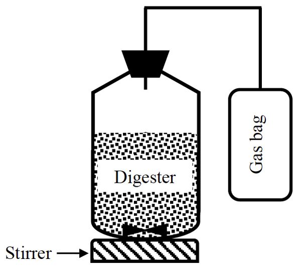
A simple anaerobic batch digestion system (Figure \(\PageIndex{7}\)) is composed of a vessel, which is normally a bottle sealed with a cap and an opening to let the biogas out. Based on the composition (TS and VS) of the substrate, an amount of the substrate that gives 3 g VS is used to start the digestion. The substrate is put in the vessel and inoculum added. The inoculum is a seed material taken from an active anaerobic digester. The pH of the digester should be approximately 7. The digester is flushed with an inert gas, such as helium or argon, for approximately two minutes to ensure anaerobic condition by removing oxygen from both liquid and head space. The digester is sealed with a rubber stopper and connected to a gas bag (called a Tedlar bag) to collect the biogas. The digester is incubated at a constant temperature (35°–50°C) for up to 25 days. During the incubation time, the contents are mixed intermittently using a stirrer or by manual shaking for about one minute, but without breaking the seal of the bottle. Each treatment should be replicated and a control using just inoculum is used to estimate the biogas produced by the inoculum alone. The collected biogas can be measured using liquid displacement or gas tight syringe. The pH is measured at the end of the digestion time. Biogas yield (L g−1 VS) is determined by dividing the cumulative biogas by the initial amount of the VS in the digester at the beginning of the digestion. The methane yield is calculated by multiplying biogas yield by the methane content of biogas that can be measured using a gas chromatograph.
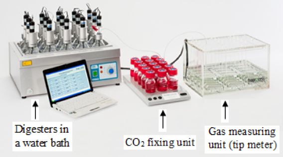
An AMPTS (Figure \(\PageIndex{8}\)) is composed of three parts: a water bath with a temperature control, a CO2 fixation unit, and a gas tip meter. The vessels are incubated in the water bath at a constant temperature. All the vessels are continuously mixed using mechanical mixers. The CO2 fixation unit is used to remove CO2 from the biogas. The gas measuring unit (tip meter) can determine the amount of methane production from each individual digester. The tip meter is connected to a data logger that continuously records the methane production. All procedures for preparing simple anaerobic batch digesters are also applied in the AMPTS.
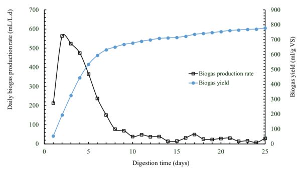
Figure \(\PageIndex{9}\) shows daily biogas production and cumulative biogas yield determined from a batch anaerobic digester, with a capacity of 1 L, treating cafeteria food waste at an initial VS loading of 4 g L−1 and a temperature of 50°C. The biogas production rates are high at the beginning of the batch digestion and then decline until reaching almost zero. This is due to the reduction of the organic matter contained in the substrate over the digestion time until all the available organic matter is consumed by microorganisms.
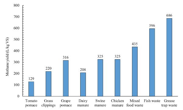
The data of methane production and remaining substrate concentration in batch digestion tests can be used to determine the first-order degradation kinetic rate constant using Equations 1.2.4, 1.2.5, and 1.2.6. Methane production is calculated by multiplying biogas production by methane content of the biogas (which is usually measured using gas chromatography). Figure 1.2.10 shows methane yields of various organic wastes after a digestion time of 25 days. As can be seen, the substrate composition affects the methane yield. The experimental data from batch digestion tests could be used to determine the proper HRT and vessel size for pilot and full-scale systems to treat a specific amount of substrate. For example, the digestion time required to convert all or part of the biodegradable organic matter in a certain substrate to biogas could be used as a basis for determining the proper HRT to convert the substrate into biogas in a continuously fed digester at the same temperature. Once the HRT is determined, the effective volume can be determined using Equation 1.2.14.
Commercial Uses of Biogas
In addition to utilizing biogas for electricity generation using generators and fuel cells, and for heating purposes, biogas can be upgraded to biomethane (also known as renewable natural gas, RNG). Biomethane is very similar to natural gas, therefore, most equipment used for natural gas can be operated with biomethane. Biomethane can be used as a transportation fuel in the form of renewable compressed natural gas (CNG) or liquefied natural gas (LNG). The U.S. Environmental Protection Agency defined renewable CNG and LNG as biogas or biogas-derived “pipeline quality gas” that is liquefied or compressed for transportation purposes. For these uses, biogas must be cleaned and upgraded, either onsite adjacent to the digester or pumped to a central facility that processes biogas from multiple digesters in the vicinity. Biomethane could also be sold to utility companies by injection into natural gas pipelines. Biomethane must meet high quality standards for injection in the pipelines (Table \(\PageIndex{5}\)).
| Quality Parameter | Value |
|---|---|
|
Water content (kg per 1000 m3 at 55.15 bar) |
0.11 |
|
Hydrogen sulfide (ppm) |
4 |
|
Total sulfur (ppm) |
17 |
|
Carbon dioxide (%) |
1 |
|
Hydrogen (%) |
0.1 |
Examples
Example \(\PageIndex{1}\)
Example 1: Theoretical methane production
Problem:
A cafeteria wants to manage waste food by using it as the feedstock for an anaerobic digestor. What is the theoretical methane production at standard temperature and pressure from 1,000 kg of organic food waste with the chemical formula C3.7H6.4O1.8N0.2? What is the expected methane content of the biogas assuming it consists of only methane and carbon dioxide?
Solution
Applying Buswell’s equation:
\( \mathrm{C}_{3.7} \mathrm{H}_{64} \mathrm{O}_{18} \mathrm{~N}_{0.2}+\left(\frac{4(3.7)-6.4-2(1.8)+3(0.2)}{4}\right) \mathrm{H}_{2} \mathrm{O} \rightarrow\left(\frac{4(3.7)+6.4-2(1.8)-3(0.2)}{8}\right) \mathrm{CH}_{4}+\left(\frac{4(3.7)-6.4+2(1.8)+3(0.2)}{8}\right) \mathrm{CO}_{2}+0.2 \mathrm{NH}_{3} \)
\( \mathrm{C}_{3.7} \mathrm{H}_{6.4} \mathrm{O}_{1.8} \mathrm{~N}_{0.2}+1.35 \mathrm{H}_{2} \mathrm{O} \rightarrow 2.125 \mathrm{CH}_{4}+1.575 \mathrm{CO}_{2}+0.2 \mathrm{NH}_{3} \)
This means that 1 mole (82.4 g) of the organic food waste produces 2.125 mole of CH4 and 1.575 mole of CO2.
Calculate methane yield using Equation 1.2.1:
\( M_{\mathrm{y}}=\frac{\left(\frac{4 a+b-2 c-3 d}{8}\right) \times 22.4}{12 a+b+16 c+14 d} \) (Equation \(\PageIndex{1}\))
\( M_{\mathrm{y}}=\frac{2.125 \times 22.4}{82.4}=0.577 \mathrm{~L} \mathrm{~g}^{-1}[\mathrm{VS}] \)
\( \text { Amount of methane production from } 1,000 \mathrm{~kg}=0.577 \times 1,000 \times 1,000=575,000 \mathrm{~L}=577 \mathrm{~m}^{3} \)
Calculate the methane content using Equation 1.2.2:
\( M_{\mathrm{C}}=\frac{\left(\frac{4 a+b-2 c-3 d}{8}\right) \times 100}{\left(\frac{4 a+b-2 c-3 d}{8}\right)+\left(\frac{4 a-b+2 c+3 d}{8}\right)} \) (Equation \(\PageIndex{2}\))
\( M_{\mathrm{C}}=\frac{2.125 \times 100}{2.125+1.575}=57.4 \% \)
Example \(\PageIndex{2}\)
Example 2: Design of an anaerobic digester for dairy manure
Problem:
A dairy farmer wants to build an anaerobic digester to treat the manure produced from 1,000 cows. Each cow produces 68 kg of manure per day. The volatile solid (VS) of the manure is 11% (wet basis). The digester is to be operated at an organic loading rate of 2 kg [VS] m−3 day−1 and a temperature of 35°C. The gas headspace volume is 10% of the working volume. Biogas yield from manure is 288 L kg−1 [VS] and the methane content is 65%. Assume all the manure produced on the dairy will be treated in the digester. Calculate:
- (a) the volume of the digester required,
- (b) the daily biogas and methane production, and
- (c) the daily energy production from biogas if the biogas has a calorific value of 23 MJ m−3.
Solution
The amount of organic matter to be treated per day (ϕom) can be calculated using the number of cows, the amount of manure produced from each cow per day, and the volatile solids contents of manure as follows:
\( \begin{aligned}
&\text { The amount of organic matter to be treated per } \operatorname{day}\left(\phi_{\mathrm{m}}\right)=\text { number of cows } \times \text { amount of manure produced from each cow } \times \text { volatile solids content of manure }=1,000 \times 68 \times\left(\frac{11}{100}\right)=7,480 \mathrm{~kg}[\mathrm{VS}] \text { day }^{-1} \end{aligned}
Calculate the working volume of the digester using Equation 1.2.13:
\( V_{\mathrm{w}}=\frac{\phi_{\mathrm{Om}}}{\mathrm{OLR}}=\frac{7,480}{2}=3,740 \mathrm{~m}^{3} \)
Calculate the total volume (Vt) of the digester using Equation 1.2.12:
\( V_{\mathrm{t}}=V_{\mathrm{w}}+V_{\mathrm{h}} \)
\( V_{\mathrm{t}}=3,740+\left(\frac{10}{100}\right)(3,740)=4,114 \mathrm{~m}^{3} \)
Calculate the daily biogas production using Equation 1.2.8:
\( B_{\mathrm{dp}}=\phi_{\mathrm{om}} B_{\mathrm{y}} \)
\( B_{dp}=7,480 \times \frac{288}{1,000} = 2,154.2 \text{m}^{3} \text {day}^{-1} \)
Calculate the methane production using Equation 1.2.9:
\( M_{dp}=B_{dp} \times M_{C} \)
\( M_{dp} = 2,154.2 \times \frac{65}{100} = 1,400.2 \text{m}^3 \text{day}^{-1} \)
Calculate the energy production using Equation 1.2.10:
\( E_{dp} = B_{dp} \times CV_{B} \)
\( E_{dp} = 2,154.2 \times 23 = 49,546.6 \ MJ \ \text{day}^{-1} \)
Example \(\PageIndex{3}\)
Example 3: Modeling and kinetics
Problem:
A batch digester with a volume of 5 L treats an organic substrate at an initial loading of 5 g [VS] L−1 for 25 days. The substrate has an ultimate methane yield of 350 mL g−1 [VS] degraded. Determine the concentration of the biodegradable substrate in the effluent and total amount of methane produced over 25 days if the first-order degradation kinetic rate constant is 0.12 day−1.
Solution
Solution:
The concentration of the biodegradable VS in the digester effluent can be calculated using Equation 1.2.4:
\( S=S_{0}e^{-kt} \) (Equation \(\PageIndex{4}\))
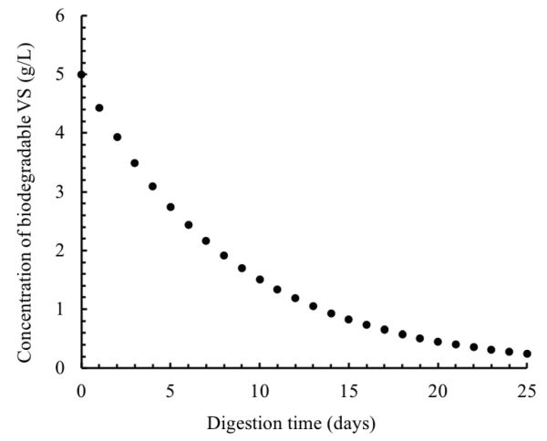
After one day of digestion, the VS concentration is:
\( S=5[e^{-0.12(1)}]=4.434 \ \text{g} \ \text{L}^{-1} \)
This calculation can be repeated for every day over the digestion time (25 days). The results of these calculations are plotted in Figure \(\PageIndex{11}\).
The amounts of the degraded organic matter and methane produced can be predicted using Equations 1.2.5 and 1.2.6. After one day of the digestion, these amounts can be calculated as:
\( S_{deg}=V_{w}(S_{0}-S) \) (Equation \(\PageIndex{5}\))
\( S_{deg}=5(5-4.434)=2.83 \ \text{g} \)
\( M_{p}=M_{y}S_{deg} \) (Equation \(\PageIndex{6}\))
\( M_{p}=350 \times 2.83 = 989.45 \ \text{mL} =0.9894 \ \text{L} \)
These calculations can be repeated for every day over the digestion time (25 days). The results of these calculations are plotted in Figure \(\PageIndex{12}\).
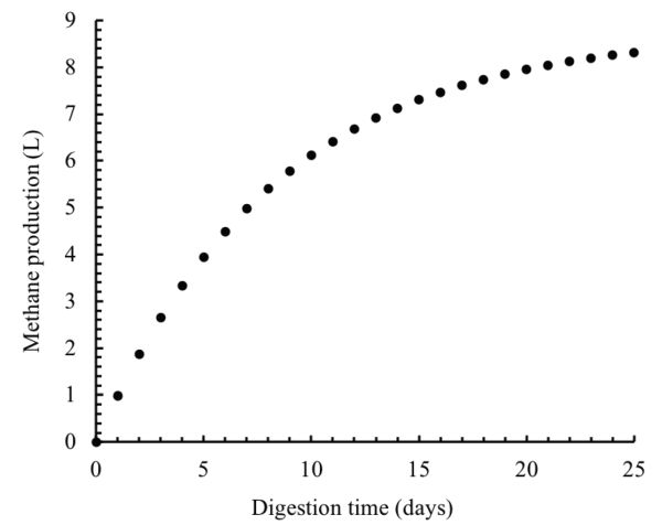
Image Credits
Figure 1. El Mashad, H. & Zhang, R. (CC By 4.0). (2020). The steps of anaerobic digestion of complex organic matter into biogas (derived from Pavlostathis and Giraldo-Gomez, 1991 and El Mashad, 2003).
Figure 2. El Mashad, H. & Zhang, R. (CC By 4.0). (2020). A schematic of suspended growth anaerobic digester.
Figure 3. El Mashad, H. & Zhang, R. (CC By 4.0). (2020). A schematic of a plug flow digester.
Figure 4. El Mashad, H. & Zhang, R. (CC By 4.0). (2020). A schematic of an anaerobic filter.
Figure 5. El Mashad and Zhang. (CC By 4.0). (2020). Relative growth rate of methanogens under psychrophilic, mesophilic and thermophilic conditions (derived from Lettinga, et al., 2001. https://www.sciencedirect.com/science/article/pii/S0167779901017012#FIG1)
Figure 6. El Mashad, H. and Zhang, R. (CC By 4.0). (2020). Relative activity of methanogenic archaea at different pH (derived from Speece, 1996; Khanal, 2008).
Figure 7. El Mashad, H. & Zhang, R. (CC By 4.0). (2020). A schematic of an experimental set-up of a batch digester system.
Figure 8. Bioprocess Control. (2020). Experimental set-up of Automated Methane Potential Test System (AMPTS). Adapted from https://www.bioprocesscontrol.com/. [Fair Use].
Figure 9. El Mashad, H. & Zhang, R. (CC By 4.0). (2020). Daily biogas production and cumulative biogas yield of cafeteria food waste.
Figure 10. El Mashad, H. & Zhang, R. (CC By 4.0). (2020). Methane yield of selected organic wastes.
Figure 11. El Mashad, H. & Zhang, R. (CC By 4.0). (2020). Concentration of biodegradable VS in the digester.
Figure 12. El Mashad, H. & Zhang, R. (CC By 4.0). (2020). Total cumulative methane production.
References
Angelidaki, I., & Sanders, W. (2004). Assessment of the anaerobic biodegradability of macropollutants. Rev. Environ. Sci. Biotechnol., 3(2), 117-129.
Batstone, D. J., Keller, J., Angelidaki, I., Kalyuzhnui, S. V., Pavlostanthis, S. G., Rozzi, A., . . . Vavilin, V. A. (2002). Anaerobic Digestion Model No. 1. IWA task group for mathematical modelling of anaerobic digestion processes. London: IWA Publishing.
Buswell, A. M., & Mueller, H. F. (1952). Mechanism of methane fermentation. Ind. Eng. Chem., 44(3), 550-552. https://doi.org/10.1021/ie50507a033.
Coke, C. (2018). Pipeline injection of biomethane in California. BioCycle, 59(3), 32. Retrieved from https://www.biocycle.net/2018/03/12/pipeline-injection-biomethane-california/.
Coombs, J. (1990). The present and future of anaerobic digestion. In A. Wheatley (Ed.), Anaerobic digestion: A waste treatment technology. Critical Rep. Appl. Chem., 31, 93-138.
El Mashad, H. M. (2003). Solar thermophilic anaerobic reactor (STAR) for renewable energy production. PhD thesis. The Netherlands: Wageningen University. Retrieved from edepot.wur.nl/121501.
Hobson, P. N., & Richardson, A. J. (1983). The microbiology of anaerobic digestion. In B. F. Pain & R. Q. Hepherd (Eds.), Anaerobic digestion of farm waste. Technical Bulletin 7. Reading, UK: The National Institute for Research in Dairying.
Khanal, S. K. (2008). Anaerobic biotechnology for bioenergy production: Principles and applications. Ames, IA: Wiley-Blackwell.
Kosaric, N., & Blaszczyk, R. (1992). Industrial effluent processing. In: J. Lederberg (Ed.), Encyclopedia of microbiology (Vol. 2, pp. 473–491). New York, NY: Academic Press.
Lettinga, G., Rebac, S., & Zeeman, G. (2001). Challenge of psychrophilic anaerobic wastewater treatment. Trends in Biotechnol. 19(9), 363-370. https://doi.org/10.1016/S0167-7799(01)01701-2.
Pavlostathis, S. G,. & Giraldo-Gomez, E. (1991). Kinetics of anaerobic treatment: A critical review. Critical. Rev. Environ. Control, 21 (5/6), 411-490. https://doi.org/10.1080/10643389109388424.
Speece, R. E. (1996). Anaerobic biotechnology for industrial wastewater treatments. Nashville, TN: Archae Press.
Stanier, R. Y., Doudoroff, M., & Adelberg, E. A. (1972). General microbiology. Englewood Cliffs, NJ: Prentice-Hall.
Stetter, K. O. (1996). Hyperthermophilic procaryotes. FEMS Microbiol. Rev., 18, 149-158. https://doi.org/10.1111/j.1574-6976.1996.tb00233.x.
Zhang, M. (2017). Energy and nutrient recovery from organic wastes through anaerobic digestion and digestate treatment. PhD diss. Davis, CA: University of California, Davis.