
5.2: Building Design for Energy Efficient Livestock Housing
- Page ID
- 46856

Andrea Costantino
TEBE Research Group
Department of Energy
Politecnico di Torino
Torino, Italy
and
Institute of Animal Science and Technology
Universitat Politècnica de València
València, Spain
Enrico Fabrizio
TEBE Research Group
Department of Energy
Politecnico di Torino
Torino, Italy
| Key Terms |
| Energy balance | Supplemental heating | Climate control |
| Mass balance | Heat recovery | Ventilation |
| Energy management | Cooling systems |
Variables
Introduction
Energy usage on farms is considered direct when used to operate machinery and climate control systems or indirect when is used to manufacture feed and agro-chemicals. Direct on-farm energy consumption was estimated to be 6 EJ yr−1, representing about 1.2% of total world energy consumption (OECD, 2008). If indirect energy is included, total farm energy consumption could be as much as 15 EJ yr−1, representing about 3.1% of global energy consumption. Housed livestock require adequate indoor climate conditions to maximize both production and welfare, particularly avoiding thermal stress. The task of the engineer is to improve the energy use efficiency of livestock housing and to minimize energy consumption. This can be achieved by improving the energy performance of the equipment used for climate control and the design of the building.
The focus of this chapter is on building design for efficient energy management in livestock housing. Improving building design requires understanding the mass and energy balance of the system to specify materials, dimensions, and equipment needed to maintain safe operating conditions. The importance of understanding the energy needs of buildings is illustrated by the report of St-Pierre et al. (2003), who estimated the economic losses by the dairy industry in the U.S. at $1.69 to $2.36 billion annually due to heat stress. Understanding and being able to use fundamental concepts for animal housing design provides the foundation for desirable welfare and more efficient production-centric animal housing.
Outcomes
After reading this chapter, you should be able to:
- • Describe the energy needs for livestock housing
- • Explain the energy management requirements of a livestock house
- • Describe the main climate control systems used for livestock housing and the features that affect the energy management
- • Calculate energy balances for livestock houses
Concepts
Energy and Mass Balance of a Livestock House
Thermodynamically, a livestock house is an open system that exchanges energy and mass (such as air, moisture, and contaminants) between the indoor and outdoor environments and the animals that occupy the internal volume (the enclosure). The law of conservation of energy and mass is the basic principle for the mass balance. The building walls, floor, and roof represent the control surfaces and enclose the control volume of the thermodynamic system represented by the livestock house and its internal surfaces, such as animals, interior walls, and equipment. Energy and mass balance equations allow the analysis of the thermal behavior of a livestock house, but calculating these balances is challenging because many factors affect the thermal behavior of these buildings. It is essential to understand which terms to consider, and what to assume as negligible.
Energy Balance
Sensible heat is the amount of heat exchanged by a body and the surrounding thermodynamic system that involves a temperature change. Latent heat is the heat absorbed or released by a substance during a phase change without a change in temperature. These two forms of heat can be illustrated using an example of heating a pot of water on a stove. Initially, the water is at room temperature (say, 25°C), and as the water is heated, its temperature increases. The heat causing the temperature increase is sensible heat and for water is equal to 4,186 kJ kg−1 K−1. When the water temperature reaches 100°C (boiling point of water at atmospheric pressure), the water changes phase from liquid to gas (steam). The heat provided during the phase change breaks the molecular bonds of the liquid water to transition to the gas phase, but the temperature does not change. The heat supplied to effect phase change is latent heat. The latent heat of vaporization for a unit of mass of water is 2,272 kJ kg−1 at 100°C and atmospheric pressure.
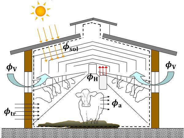
The energy balance of a livestock house, considering only the sensible heat, can be written as follows (Panagakis and Axaopoulos, 2008):
\[ \phi_{a}+\phi_{tr}+\phi_{sol}+\phi_{f}+\phi_{v}+\phi_{m}+(\gamma_{fog}\cdot \phi_{H})=\sum^{n}_{k=1}(M_{el,k}\cdot C_{el,k})\cdot \frac{dT_{air,i}}{dt} \]
where \(\phi_{a}\) = sensible heat flow from the animals inside the enclosure (W)
\(\phi_{tr}\) = sensible heat flow due to transmission through the control surfaces but excluding the floor (W)
\(\phi_{sol}\) = sensible heat flow due to solar radiation through both opaque and glazed building elements (W)
\(\phi_{f}\) = sensible heat flow due to transmission through the floor (W)
\(\phi_{v}\) = sensible heat flow due to ventilation (W)
\(\phi_{m}\)= sensible heat flow from internal sources, such as motors and lights (W)
\(\gamma_{fog}\)= Boolean variable for the presence (\(\gamma_{fog}\)=1) or not (\(\gamma_{fog}\)=0) of a fogging system inside the livestock house
\(\phi_{fog}\)= sensible heat flow due to fogging system (W)
\(\gamma_{H}\)= Boolean variable for the presence (\(\gamma_{H}\)=1) or not (\(\gamma_{H}\)=0) of a supplemental heating system inside the livestock house
\(\phi_{H}\)= sensible heat flow due to supplemental heating system (W)
\(M_{el,k}\) = mass of the kth building element (kg)
\(C_{el,k}\) = total heat capacity of kth building element (kJ kg−1 K−1)
\(\frac{dT_{air,i}}{dt}\) = variation of the indoor air temperature \(T_{air,i}\) with time t
When using Equation 5.2.1 for calculations and sizing, pay attention to the heat flows because each term could be positive or negative depending on the physical context. Usually, heat flows coming into a control volume (the animal house) are positive, and the ones flowing out are negative. For example, in Equation (5.2.1), the terms \(\phi_{a}\) and \(\phi_{sol}\) are always positive or zero, since they represent incoming heat flow from animals and solar radiation, respectively, while the values of \(\phi_{tr}\) and \(\phi_{v}\) could be positive or negative, depending on the difference in temperature inside and outside the animal house. The term \(\phi_{f}\) depends on the floor construction. Although \(\phi_{tr}\) and \(\phi_{f}\) are both transmission heat flows through the control surface, they are always separated. Estimating the heat transfer through the ground is very challenging (Albright, 1990; Panagakis and Axaopoulos, 2008; Costantino et al., 2017), for example, in pig houses with ventilated pits for manure storage. To simplify the energy balance, the term \(\phi_{tr}\) is often considered as the sum of \(\phi_{tr}\) and \(\phi_{f}\) and a corrective coefficient is used when \(\phi_{f}\) is calculated.
The term \(\phi_{fog}\) is always negative because it represents the sensible heat removed by water droplets of a fogging system. A fogging system provides cooling inside the animal house by putting a haze of tiny water droplets in the air to provide evaporative cooling for the animals. The term \(\phi_{H}\) is always positive. The parameters \(\gamma_{fog}\) and \(\gamma_{H}\) should not have a value of 1 at the same time but can both be 0.
Sensible heat from the animals, \(\phi_{a}\), depends on species and body mass and ambient temperature. Sensible and latent heat values can be found in the literature, for example from ASABE (2012), Hellickson & Walker (1983), or Lindley & Whitaker (1996), and more detailed data are available in Pedersen and Sällvik (2002), who express sensible and latent heat from animals as a function of animal weight, indoor air temperature, and animal activity. In complex animal houses the sensible heat flow from internal sources, such as motors (fans and automatic feeding systems) and lights term (\(\phi_{m}\)) can be included (Albright, 1990), but in many calculations it is excluded because is very small compared with \(\phi_{a}\) (Midwest Plan Service, 1987). That exclusion is further justified when energy-efficient technologies such as LED/gas-discharge lamps and brushless motors are used.
The product \(M_{el}\cdot C_{el}\) is the lumped effective heat capacity of a building element expressed in kJ K−1. For each building element (walls and roof) the amount or mass of material must be known, and the amount of heat energy needed to raise the temperature of a unit mass of the material by one degree Celsius. The fraction \(\frac{dT_{air,i}}{dt}\) represents the variation of the indoor air temperature through time. This side of the equation represents the change in temperature of the building itself.
It is possible to include additional terms to Equation 5.2.1 (Albright, 1990; Esmay and Dixon, 1986) such as the sensible heat flow to evaporate the water inside the control volume from structures such as water troughs and a slurry store (\(\phi_{e}\)). Some authors consider it important (Hamilton et al., 2016), while others do not (Midwest Plan Service, 1987). Liberati and Zappavigna (2005) consider sensible heat exchange between manure (especially when collected in pits) and the air inside the enclosure (\(\phi_{man}\)) to be important in large-scale houses equipped with storage pits and manure when it is not removed frequently. A Boolean variable \(\gamma_{man}\) may generalize Equation 5.2.1 further.
Equation 5.2.1 is a dynamic energy balance. If a large time step (perhaps a week or more) is assumed it can be written for steady-state conditions, meaning that the state variables that describe the system can be considered constant with time, and the terms of the balance represent the average values for the system. For large time steps or in steady-state conditions with constant indoor and outdoor air temperature, heat accumulation by the building itself can be considered to be zero, so Equation 5.2.1 becomes:
\[ \phi_{a}+\phi_{tr}+\phi_{sol}+\phi_{v}+\gamma_{fog}\cdot \phi_{fog}=0 \]
To obtain the energy balance of a livestock house in cold condition requiring supplemental heating, the energy balance becomes:
\[ \phi_{a}+\phi_{tr}+\phi_{H}+\phi_{sol}+\phi_{v}=0 \]
Figure 5.2.1 presents an illustration of the sensible heat balance of Equation 5.2.3 for simple dairy cow housing. Equation 5.2.3 can be used to design a basic livestock house. Undoubtedly, the presented formulation is a simplification, and in literature, other terms are introduced in the energy balance. The calculation of each term of the energy balance of Equation 5.2.3 is provided in greater detail later in this chapter.
Mass Balance
Mass balances are necessary to plan the management of contaminants, such as carbon dioxide (CO2), hydrogen sulfide (H2S), and ammonia (NH3), produced by the animals (Esmay and Dixon, 1986) and to regulate the indoor environment temperature, moisture content, and relative humidity. Along with temperature and relative humidity, the indoor air quality (IAQ) must be controlled by ventilation to avoid animal health problems. Calculating ventilation requirements for contaminant control is a mass balance problem. With low indoor air temperatures, a minimum ventilation flow rate (base ventilation) is used to dilute contaminants such as H2S and NH3. The minimum ventilation flow rate can be increased to reduce the moisture content. When the indoor air temperature is higher than the cooling setpoint temperature used to maintain animal comfort, the ventilation flow rate must be increased to cool the animals (Esmay and Dixon, 1986). The maximum ventilation flow rate must avoid high airspeeds that hurt animal welfare. If cooling cannot be achieved using mass flow, a fogging system can be used. The ventilation airflow can be expressed in m3s−1, m3h−1 or as ach (air changes per hour), which indicates how many times the volume of air inside the house is changed in one hour.
To estimate the ventilation flow rate for moisture control in a simple livestock house, Equation 5.2.4 (Panagakis and Axaopoulos, 2008) can be used:
\[ \dot{V}_{air}\cdot \rho_{air}\cdot(x_{air,i}-x_{air,o})+\dot{m}_{a}+(\gamma_{fog} \cdot \dot{m}_{fog})=\rho_{air,i} \cdot V_{air,i} \cdot \frac{dx_{air,i}}{dt} \]
where \(\dot{V}_{air}\) = ventilation air flow rate (m3 s−1)
\(\rho_{air}\) = volumetric mass density (kg m3)
\(x_{air,o}\) = specific humidity of the outdoor air (kgvapor kgair−1)
\(x_{air,i}\) = specific humidity of the indoor air (kgvapor kgair−1)
\(\dot{m}_{a}\)= animal water vapor production (kgvapor s−1)
\(\gamma_{fog}\) = Boolean variable that indicates the presence of fogging system
\(\dot{m}_{fog}\) = water added through fogging (kgvapor s−1)
\(\rho_{air,i}\) = volumetric mass density of inside air (kg m−3)
\(V_{air,i}\) = volume of the inside air (m3)
\(\frac{dx_{air,i}}{dt}\) = variation of \(x_{air,i}\) in time t
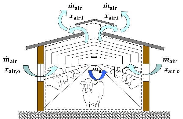
In steady-state conditions and not considering the presence of fogging systems, the mass balance (Figure 5.2.2) can be simplified as:
\[ \dot{m}_{air} \cdot x_{air,i} - \dot{m}_{air} \cdot x_{air,i} + \dot{m}_{a} = 0 \]
Equation 5.2.5 is the basic formulation of the moisture mass balance in steady-state conditions for livestock houses.
Energy Management Calculations
The basis for sensible energy and mass balance calculations for livestock housing are Equations 5.2.3 and 5.2.5, respectively. In the following sections, the determination of each term of the energy balance (Equation 5.2.3) is presented. A similar approach could be used for Equation 5.2.5.
Heat Flow from the Reared Animals (\(\phi_{a}\))
The animals produce and contribute considerably to heat flow in their housing. In cool conditions, this heat flow can help warm the building and decrease the need for supplemental heat. In warm conditions, this heat flow should be removed to avoid overheating and causing animal heat stress. Animals need to emit heat (both sensible and latent heat) for regulating their body temperature and maintaining their body functions. As an animal grows (usually the desired outcome of a meat production system, but not for dairy and laying hens), the animal produces more heat. The amount of heat also depends on indoor air temperature, production targets (such as the mass of eggs, milk, or meat), and the energy concentration of the feedstuff. Estimating heat production is also essential to calculate ventilation requirements.
Standard values for heat production are available (CIGR, 1999; ASABE, 2012), but a specific calculation is possible (Pedersen and Sällvik, 2002). First the total heat produced, \(\phi_{a,tot}\) (sum of the sensible and latent heat), for the animal house is calculated for an indoor air temperature of 20°C. The formulation of the equation depends on animal species and production:
Broilers: \[ \phi_{a,tot} =10.62\cdot w_{a}^{0.75} \cdot n_{a} \]
Laying hens: \[\phi_{a,tot} =(6.28\cdot w_{a}^{0.75} + 25\cdot Y_{eggs}) \cdot n_{a} \]
Fattening pigs: \[ \phi_{a,tot} =(5.09 \cdot +[1-(0.47+0.003 \cdot w_{a})] \cdot [5.09 \cdot w_{a}^{0.75} \cdot (Y_{feed}-1)]) \cdot n_{a} \]
Dairy cows: \[ \phi_{a,tot} =(5.6\cdot w_{a}^{0.75} + 22\cdot Y_{milk} +1.6\cdot 10^{-5}\cdot Y_{pregnancy}^{3} )\cdot n_{a} \]
where \(w_{a}\) = average animal live weight (kg)
\(n_{a}\) = number of animals inside the livestock house (animals)
\(Y_{eggs}\) = egg production (kg day−1), usually between 0.04 (brooding production) and 0.05 kg day−1 (consumer eggs)
\(Y_{feed}\) = dimensionless coefficient related to the daily feed energy intake by the pigs (values of \(Y_{feed}\) are presented in Table 5.2.1)
\(Y_{milk}\) = milk production (kg day−1)
\(Y_{pregnancy}\) = number of days of pregnancy (days)
Next, the sensible heat produced (\(\phi_{a}\)) at a given indoor air temperature is calculated. If the indoor air temperature is in the thermoneutral zone, that is, a temperature range where the animal heat dissipation is constant (Pedersen and Sällvik, 2002) and the energy fraction used by animals for maintaining their homeothermy is at a minimum, at the house level \(\phi_{a}\) can be calculated as:
| Pig Body Mass (kg) |
Yfeed | ||
|---|---|---|---|
| Rate of Gain: 700 g day−1 | Rate of Gain: 800 g day−1 | Rate of Gain: 900 g day−1 | |
|
20 |
3.03 |
3.39 |
3.39 |
|
30 |
2.79 |
3.25 |
3.25 |
|
40 |
2.60 |
3.22 |
3.43 |
|
50 |
2.73 |
3.16 |
3.41 |
|
60 |
2.78 |
3.16 |
3.40 |
|
70 |
2.84 |
3.12 |
3.40 |
|
80 |
2.83 |
3.04 |
3.38 |
|
90 |
2.74 |
2.79 |
3.18 |
|
100 |
2.64 |
2.57 |
2.98 |
|
110 |
2.52 |
2.40 |
2.78 |
|
120 |
2.36 |
2.25 |
2.60 |
Broiler house: \[ \phi_{a}=\{0.61 \cdot[1000+20 \cdot (20-T_{air,i})]-0.228 \cdot T_{air,i}^{2} \} \cdot n_{hpu} \]
Laying hen house: \[ \phi_{a}=\{0.67 \cdot[1000+20 \cdot (20-T_{air,i})]-9.8\cdot 10^{-8} \cdot T_{air,i}^{6} \} \cdot n_{hpu} \]
Fattening pig house: \[ \phi_{a}=\{0.62 \cdot[1000+12 \cdot (20-T_{air,i})]-1.15\cdot 10^{-7} \cdot T_{air,i}^{6} \} \cdot n_{hpu} \]
Dairy cow house: \[ \phi_{a}=\{0.71 \cdot[1000+4 \cdot (20-T_{air,i})]-0.408 \cdot T_{air,i}^{2} \} \cdot n_{hpu} \]
where \(T_{air,i}\) = indoor air temperature (°C)
\(n_{hpu}\) = the number of heat-producing units (hpu) that are present inside the livestock house
One hpu is defined as the number of animals that produces 1000 W of total heat (sum of sensible and latent heat) at an indoor air temperature of 20°C and can be calculated as:
\[ n_{hpu} = \frac{\phi_{a,tot}}{1000} \]
where \(\phi_{a,tot}\) is calculated using Equations 5.2.6, 5.2.7, 5.2.8, or 5.2.9 depending on species and production system. Out of the thermoneutral zone, no clear relationship can be found between indoor air temperature and total heat production, but values can be calculated using the formulations present in Pedersen and Sällvik (2002).
Transmission Heat Flow through the Building Envelope (\(\phi_{tr}\))
The term \(\phi_{t}\) is being taken to represent the heat flow through the walls, roof, windows, doors and floor. It is calculated as (European Committee for Standardization, 2007):
\[ \phi_{tr}=[\sum^{n}_{j=1}(b_{tr,j} \cdot U_{j} \cdot A_{j})] \cdot (T_{air,o}-T_{air,i}) \]
where btr = dimensionless correction factor between 0 and 1
\(U_{j}\) = thermal transmittance of the j building element (W m−2 K−1)
\(A_{j}\) = total area of the j building element (m2)
\(T_{air,o}\) = outdoor air temperature (°C)
The factor \(b_{tr}\) is used to correct the heat flow when the forcing temperature difference is not the difference between the indoor and outdoor air, for example when the heat flow occurs toward unconditioned spaces (e.g. material storages and climate control rooms) or through the ground. In these cases, the air temperature difference between inside and outside can be used but the heat flow is decreased using \(b_{tr}\). This coefficient can be computed in two cases: (1) if the adjacent space temperature is fixed and known, or (2) if all the heat transfer coefficients between the considered spaces can be numerically estimated. In most situations, \(b_{tr}\) (unitless) is obtained from standards, (e.g., Table 5.2.2).
| Type of Unconditioned Space | btr |
|---|---|
|
Space with 1 wall facing on the outdoor environment |
0.40 |
|
Space with 2 walls facing on the outdoor environment (no doors) |
0.50 |
|
Space with 2 walls facing on the outdoor environment (with doors) |
0.60 |
|
Space with 3 walls facing on the outdoor environment (with doors) |
0.80 |
|
Floor in direct contact with the ground |
0.45 |
|
Ventilated floor (e.g. pits and under-floor cavity) |
0.80 |
Heat Flow Due to a Supplemental Heating System (\(\phi_{H}\))
In most of the cases, \(\phi_{H}\) is the unknown of the problem and the energy balance is solved with the aim of finding its value. A typical example is to solve the energy balance of Equation 5.2.3 for finding \(\phi_{H}\) and sizing the heating capacity of the supplemental heating system. In other cases, \(\phi_{H}\) could be equal to zero and the unknown of the problem could be ![]() with the aim of finding the needed ventilation flow rate to maintain a certain indoor air temperature and to cool the reared animals. Rarely, \(\phi_{H}\) has to be estimated. For example, \(\phi_{H}\) has to be estimated when the energy balance is solved with the aim of evaluating the indoor air temperature in given specific boundary conditions. An easy way to estimate \(\phi_{H}\) is to consider the heating capacity reported in the technical datasheet of the equipment for supplemental heating.
with the aim of finding the needed ventilation flow rate to maintain a certain indoor air temperature and to cool the reared animals. Rarely, \(\phi_{H}\) has to be estimated. For example, \(\phi_{H}\) has to be estimated when the energy balance is solved with the aim of evaluating the indoor air temperature in given specific boundary conditions. An easy way to estimate \(\phi_{H}\) is to consider the heating capacity reported in the technical datasheet of the equipment for supplemental heating.
More details about the supplemental heating systems are described below, in the Application section.
Heat Flow from Solar Radiation (\(\phi_{H}\))
The heat flow due to solar radiation is dependent on the season, the farm location, and features of the building. In general terms, the solar heat flow can be split into two terms as follows (International Organization for Standardization, 2017):
\[ \phi_{sol} = \sum^{q}_{n=1}\phi_{sol,op,q} + \sum^{k}_{n=1} \phi_{sol,gl,k} \]
where \(\phi_{sol,op,q}\) = heat flows on the q opaque (e.g. walls and roof) surfaces (W)
\(\phi_{sol,gl,k}\)= heat flows on the k glazed (windows) surfaces (W)
For a generic opaque surface \(\phi_{sol,op,q}\) is calculated as:
\[ \phi_{sol, op,q} = A_{q} \cdot U_{q} \cdot \alpha_{q} \cdot R_{ex} \cdot I_{sol,q} \cdot F_{sh,q} \]
where \(\alpha_{q}\) = solar absorption coefficient of the considered surface depending on the surface color (0.3 for light colors, 0.9 for dark colors)
\(R_{ex}\) = external surface heat resistance (m2 K−1 W−1), generally assumed equal to 0.04 m2 K−1 W−1
\(I_{sol,q}\) = solar irradiance incident on the considered surface (W m−2)
Fsh,q = shading correction factor
For a generic glazed surface k, \(\phi_{s,gl,k}\) is calculated as:
\[ \phi_{s,gl,k} = A_{k} \cdot g_{gl} \cdot I_{sol,k} \cdot (1-F_{fr}) \cdot F_{sh,k} \cdot F_{sh,gl,k} \]
where \(g_{gl}\) = total solar energy transmittance of the transparent surface
\(F_{fr}\) = frame area fraction
\(F_{sh,gl,k}\) = shading reduction factor for movable shading provisions
The shading factors for both opaque and glazed components can be excluded for most livestock housing because they increase the complexity of the calculation, but they do not greatly affect the results.
Heat Flow Due to the Ventilation System (\(\phi_{v}\))
The heat load due to the ventilation system can be expressed as
\[ \phi_{v} = \rho_{air} \cdot c_{air} \cdot \dot{V} \cdot (T_{air,sup}-T_{air,i}) \]
where \(\rho_{air}\) = air volumetric mass density (kg m−3)
\(c_{air}\) = air specific heat capacity (W h kg−1 K−1)
\(\dot{V}\) = ventilation flow rate (m3 h−1)
\(T_{air,sup}\) = supply air temperature (°C)
In the cool season, \(T_{air,sup}\) usually has the same value of \(T_{air,o}\), since the ventilation uses outdoor air. In the warm season, \(T_{air,sup}\) could have values lower than\(T_{air,o}\), since outdoor air is cooled before entering inside the building. The value of \(T_{air,sup}\) can be estimated using the direct saturation effectiveness \(\varepsilon\) (%) of an evaporative pad system, calculated as (ASHRAE, 2012):
\[ \varepsilon = 100 \cdot \frac{T_{air,o,db}-T_{air,sup,bd}}{T_{air,o,db}-T_{air,o,wb}} \]
where \(T_{air,o,db}\) = dry-bulb outdoor air temperature (°C)
\(T_{air,sup,db}\) = dry-bulb temperature of the supply air leaving the cooling pad (°C)
\(T_{air,o,wb}\) = wet-bulb temperature of the outdoor air entering in the pad (°C)
Equation 5.2.20 can be rearranged to estimate the air supply temperature (\(T_{air,sup,db}\)) in presence of evaporative pads for use in Equation 5.2.19.
Applications
The concepts describe the basis for calculating the energy balance of a simple animal house. These are usually quite straightforward structures built to standard designs, which differ around the world but serve a similar function of making animal production more efficient for the farmer. The calculation for the design of the animal house (the control structure) necessarily assumes a typical or average environment. In reality, weather and production management mean that there have to be components of the system that are dynamic and respond to external conditions. In this section, some of the technology required to help maintain a safe and efficient living environment for the animals are discussed.
Heating Animal Houses
Supplemental Heating Systems
In cold weather, a supplemental heat source may be needed to reach the air setpoint temperature for guaranteeing adequate living conditions for the livestock. This is common at the beginning of the production cycle when animal heat production is small and in cold seasons of the year. This energy consumption represents a major fraction of the total direct energy consumption of the farm (Table 5.2.3) and can be calculated using Equation 5.2.3.
Supplemental heating systems can be classified into localized heating and space heating systems. Localized heating systems create temperature variations in the zones where animals are reared. This allows young animals to move to a zone for optimum thermal comfort. To design a localized heating system, the term \(\phi_{m}\) (as used in Equation 5.2.1) would have to be factored into the calculation to account for heat flow between the internal zones. Localized heating usually uses radiant heat, such as infrared lamps (for piglets) or infrared gas catalytic radiant heaters (for broilers). These systems emit 70% of their heat by radiation and the remaining 30% by convection; the radiation component directly heats the animals and floor while the convection component heats the air.
Space heating systems create a more uniform thermal environment. They are easier to design, manage, and control than localized heating systems, but they tend to have higher energy consumption. Space heating is usually based on a convection system using warm air. Heat is produced in boilers or furnaces and then is transferred into the building when needed.
An alternative is to use direct air heating in the house. Direct heating can be cheaper to install, but requires more maintenance to deal with contaminants, dust, and moisture (Lindley and Whitaker, 1996). Also, there is a need to vent exhaust fumes and CO2 so ventilation flow rates have to be increased, requiring more energy consumption (Costantino et al., 2020). In other agricultural buildings, such as greenhouses, the warm air is recirculated to decrease energy consumption. In livestock houses this practice is strongly not recommended since the concentration of contaminants that are produced in the enclosure make the IAQ even worse.
| Livestock House | Operation | Percentage of Electrical Energy (of the total) |
Percentage of Thermal Energy (of the total) |
|---|---|---|---|
|
Broiler Houses |
ventilation |
39% |
- |
|
supplemental heating |
27% |
96% |
|
|
lighting |
9% |
- |
|
|
feeding distribution |
20% |
- |
|
|
litter distribution and manure removal |
- |
3% |
|
|
manure transportation and disposal |
- |
1% |
|
|
product collecting and package |
5% |
- |
|
|
Laying Hen Houses |
ventilation |
44% |
- |
|
supplemental heating |
- |
- |
|
|
lighting |
15% |
- |
|
|
feeding distribution |
5% |
- |
|
|
litter distribution and manure removal |
2% |
33% |
|
|
manure treatment |
27% |
- |
|
|
manure transportation and disposal |
- |
67% |
|
|
product collecting and package |
7% |
- |
|
|
Pig Houses |
ventilation and supplemental heating |
48% |
69% |
|
lighting |
2% |
- |
|
|
feeding preparation |
11% |
- |
|
|
feeding distribution |
19% |
- |
|
|
litter care and manure removal |
4% |
1% |
|
|
manure treatment |
4% |
- |
|
|
manure transportation and disposal |
12% |
30% |
|
|
Dairy Cow Houses |
ventilation |
20% |
- |
|
lighting |
8% |
- |
|
|
feeding |
17% |
52% |
|
|
milking |
16% |
6% |
|
|
milk cooling |
12% |
- |
|
|
litter care |
- |
7% |
|
|
manure removal |
8% |
5% |
|
|
manure treatment |
18% |
4% |
|
|
manure transportation and disposal |
1% |
26% |
Localized and space heating systems can be used together or coupled with floor heaters to improve the control of the indoor climate conditions. Floor heating is usually through hot water pipes or electric resistance cables buried directly in the floor, but this can cause greater evaporation and a rise in the air moisture content.
The most common energy sources for heating are electricity, natural gas, propane, and biomass. Solar energy represents an interesting solution for providing supplemental heating, but peak availability is during warm seasons and the daytime when heat demand is lowest.
Heat Recovery Systems
To maintain IAQ, indoor air is replaced by fresh outdoor air to dilute contaminants and decrease moisture content. During heating periods, every cubic meter of fresh air that is introduced inside the livestock house is heated to reach the indoor air set point temperature. The heat of the exhausted air is lost. When the outdoor air is cold, heating the fresh air requires considerable energy; ventilation accounts for 70% to 90% of the heat losses in typical livestock houses during the winter season (ASHRAE, 2011).
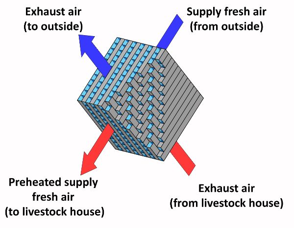
To improve energy performance especially in cold climates, heat recovery can be used. In livestock houses, air-to-air heat recovery systems are used to transfer sensible heat from an airstream at a high temperature (exhaust air) to an airstream at a low temperature (fresh supply air) (ASHRAE, 2012). The heat transfer happens through a heat exchange surface (a series of plates or tubes) that separates the two airstreams, avoiding the cross-contamination of fresh supply air with the contaminants in the exhaust air. The most common type of heat exchanger used in livestock houses is cross-flow (Figure 5.2.3). The recovered heat directly increases the temperature of the fresh supply air, decreasing the supplemental heat that is needed to reach the indoor air set point temperature. Heat recovery systems mainly transfer sensible heat but, under certain psychrometric conditions, even part of the latent heat of the exhaust air can be recovered. For example, when the outdoor air is very cool, the water vapor contained in the exhaust air condenses and releases the latent heat of condensation increasing the temperature of the fresh air.
In practice, heat exchanger effectiveness is the ratio between the actual transfer of energy and the maximum possible transfer between the airstreams (ASHRAE, 1991). In livestock houses this is usually between 60% and 80%, because of freezing and dust accumulation on the heat-exchanging surfaces (ASHRAE, 2011). A buildup of dust reduces the heat transfer between the airstreams and reduces the flow rate. In addition, gases and moisture in exhaust air can damage the heat-exchanging surface. Filtration, automatic washing, insulation, and defrost controls can be used to avoid problems with heat exchange.
Cooling Animal Houses
Cooling Systems
In warmer conditions, cooling is required to reduce the indoor air temperature and to alleviate animal heat stress. Air flow driven by fans is used to remove the heat generated by animals and from solar radiation. With high indoor air temperature and in heat stress situations, greater air velocities around the animals are preferred because the skin temperature of the animals is reduced through the increasing convective heat exchange.
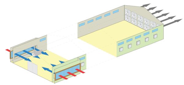
When the difference between outdoor air and indoor air temperatures is small, cooling ventilation is less effective because the needed air flow rates require air velocities too great for animal comfort. To overcome this problem, water cooling and evaporative cooling can be used (Lindley and Whitaker, 1996). Water cooling consists of sprinkling or dripping water directly on the animals to remove heat from their bodies through evaporation. Evaporative cooling uses heat from the indoor air to vaporize water and thus decrease indoor air temperature with either a fogging system or evaporative pads. Foggers release a mist of tiny water droplets directly inside the enclosure. Evaporative pads are used in livestock houses with exhaust ventilation systems (Figure 5.2.4). In these systems, exhaust fans force out the indoor air creating a negative pressure difference between inside and outside the house. This pressure difference pulls the fresh outdoor air inside the house through the evaporative pads, decreasing its temperature by some degrees as a function of the direct saturation effectiveness, \(\varepsilon\) (ASHRAE, 2012) (Equation 5.2.20). From a technical point of view, \(\varepsilon\) is the most exciting feature of an evaporative pad, and it ranges between 70% and 95% for commercially available evaporative pads. This value is directly proportional to the pad thickness (from 0.1 to 0.3 m) (ASHRAE, 2012) and inversely proportional to the air velocity through the pad. The highest efficiencies are with air velocity between 1.0 and 1.4 m s−1 (ASHRAE, 2011). The value of \(\varepsilon\) is also influenced by the age and the maintenance of the pad; \(\varepsilon\) can decrease to 30% in old and poorly maintained pads (Costantino et al., 2018).
Evaporative pads affect energy consumption in two ways. On the one hand, they decrease the temperature of the air that is used to ventilate the house, which means a reduction in the ventilation flow rate needed to maintain the indoor air setpoint temperature. On the other hand, they increase the pressure difference between the inside and outside the house, so for the same air flow rate, the fans in a livestock house equipped with evaporative pads require higher electricity consumption. Finally, the use of evaporative pads requires extra electrical energy due to the circulation pumps used to move the water from storage for wetting the top of the pads.
Ventilation Systems
The effectiveness of ventilation inside a livestock house depends on the selection, installation, and operation of the ventilation equipment, such as air inlets, outlets, control systems, and fans.
Fans are classified as centrifugal or axial, according to the direction of the airflow through the impeller (ASHRAE, 2012). Axial fans draw air parallel to the shaft axis (around which the blades rotate) and exhaust it in the same direction. Centrifugal fans exhaust air by deflection and centrifugal force. In centrifugal fans air enters next to the shaft due to the rotation of the impeller and then moves perpendicularly from the shaft to the opening where it is exhausted. Axial fans are usually used in livestock housing because the primary goal is to provide a high airflow rate and not to create a high-pressure difference across the fan. Fans cause considerable energy consumption in livestock houses (Costantino et al., 2016), as shown in Table 5.2.3, but are typically bought based on purchase cost, not operating costs. When fans are installed in the livestock houses, a reduction in efficiency has to be expected due to the wear of the mechanical connections (ASHRAE, 2012).
Examples
Example \(\PageIndex{1}\)
Example 1: Heat flow through a building envelope
Problem:
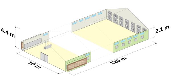
Determine the total steady-state transmission heat flow through the building envelope of the gable roof broiler house presented in Figure 5.2.5. The thermophysical properties of the envelope elements are shown in Table 5.2.4. For the calculation, assume the indoor air temperature is 23°C and the outdoor air temperature is 20°C.
Solution
The total transmission heat flow through the envelope should be calculated through Equation 5.2.15. In the summation, all the envelope elements of the broiler house must be considered. In this broiler house, the various products \((b_{tr,j} \cdot U_{j} \cdot A_{j})\) of the summation of Equation 5.2.15 are:
| Building Element |
Area (m2) |
U (W m−2 k−1) |
btr(-) |
|---|---|---|---|
|
North wall |
195 |
0.81 |
1 |
|
South wall |
195 |
0.81 |
1 |
|
East wall |
18 |
0.81 |
1 |
|
West wall |
33 |
0.81 |
1 |
|
Roof |
1320 |
1.17 |
1 |
|
Floor |
1200 |
0.94 |
0.45 |
|
Door (east) |
15 |
1.51 |
1 |
|
North windows |
57 |
3.60 |
1 |
|
South windows |
57 |
3.60 |
1 |
\( \phi_{tr} = [\sum^{n}_{j=1}(b_{tr,j} \cdot U_{j} \cdot A_{j})] \) (Equation \(\PageIndex{15}\))
\( b_{tr,walls} \cdot U_{walls} \cdot A_{walls} = 1 \cdot 0.81 \frac{W}{m^{2} \cdot K} \cdot 441 m^{2} = 357.2 \frac{W}{K} \)
\( b_{tr,roof} \cdot U_{roof} \cdot A_{roof} = 1 \cdot 1.17 \frac{W}{m^{2} \cdot K} \cdot 1320 m^{2} = 1544.4 \frac{W}{K} \)
\( b_{tr, doors} \cdot U_{doors} \cdot A_{doors} = 1 \cdot 1.51 \frac{W}{m^{2} \cdot K} \cdot 15 m^{2} = 22.7 \frac{W}{K} \)
\( b_{tr, windows} \cdot U_{windows} \cdot A_{windows} = 1 \cdot 3.60 \frac{W}{m^{2} \cdot K} \cdot 114 m^{2} = 410.4 \frac{W}{K} \)
The U-value of the floor of the broiler house is 0.94 W m−2 K−1. This value was calculated considering that the floor was made by a reinforced concrete screed and a waterproofing sheet directly in contact with the ground. In the transmission heat flow via ground, the \(b_{tr}\) coefficient has to be considered. Considering that the floor of the broiler house is in direct contact with the ground, \(b_{tr,floor}\) can be assumed equal to 0.45 (value from Table 5.2.2). The calculation is:
\( b_{tr, floor} \cdot U_{floor} \cdot A_{floor} = 0.45 \cdot 0.94 \frac{W}{m^{2} \cdot K} \cdot 1200 m^{2} = 507.6 \frac{W}{K} \)
Considering the previously calculated values, the sum is:
\( \sum^{n}_{j=1} (b_{tr,j} \cdot U_{j} \cdot A_{j}) = 2842.3 \frac{W}{K} \)
Finally, the heat flow can be calculated considering the temperature difference between inside and outside as:
Example \(\PageIndex{2}\)
Example 2: Sensible heat flow in a broiler house
Problem:
Determine the sensible heat flow produced at the house level by a flock of 14,000 broilers at an indoor air temperature of 23°C. The average weight of the broilers is 1.3 kg.
Solution
The total heat production \(\phi_{a,tot}\) from a broiler flock at an indoor air temperature of 20°C is defined by Equation 5.2.6 that reads
\( \phi_{a,tot}=10.62 \cdot w_{a}^{0.75} \cdot n_{a} \) (Equation \(\PageIndex{6}\))
Considering the given boundary conditions, Equation 5.2.6 becomes:
\( \phi_{a,tot}=10.62 \cdot 1.3^{0.75} \cdot 14,000 = 181,013.1\ W \)
Before calculating \(\phi_{a}\), nhpu has to be calculated according to Equation 5.2.14:
\( n_{hpu} = \frac{\phi_{a,tot}}{1000} \) (Equation \(\PageIndex{14}\))
\( n_{hpu} = \frac{181,031.1\ W}{1000 \frac{W}{hpu}} = 181.01\ hpu \)
Finally, \(\phi_{a}\) calculated at 23°C of \(T_{air,i}\) is (from Equation 5.2.10):
\( \phi_{a} = \{0.61 \cdot [1000+20 \cdot(20-T_{air,i})] -0.228 \cdot T_{air,i}^{2} \} \cdot n_{npu} \) (Equation \(\PageIndex{10}\))
\( \phi_{a} = \{0.61 \cdot [1000+20 \cdot(20-23^\circ C)] -0.228 \cdot (23^\circ C)^{2} \} \cdot 181.01 = 81,959.2\ W \)
The broiler flock in this example produces around 82 kW of sensible heat.
Example \(\PageIndex{3}\)
Example 3: Solar based heat flow
Problem:
Determine the value of \(\phi_{sol}\) considering the boundary conditions shown in Table 5.2.5 and using the same broiler house of Examples 5.2.1 and 5.2.2.
Solution
The first step for determining \(\phi_{sol}\) is to calculate \(\phi_{sol,op}\) for each opaque building element according to Equation 5.2.17, as:
| Building Element |
Area (m2) |
U (W m−2 k−1) |
α (-) | ggl(-) | Isol (W m−2) |
|---|---|---|---|---|---|
|
North wall |
195 |
0.81 |
0.3 |
- |
142 |
|
South wall |
195 |
0.81 |
0.3 |
- |
559 |
|
East wall |
18 |
0.81 |
0.3 |
- |
277 |
|
West wall |
33 |
0.81 |
0.3 |
- |
142 |
|
Roof |
1320 |
1.17 |
0.9 |
- |
721 |
|
Floor |
1200 |
0.94 |
- |
- |
- |
|
Door (east) |
15 |
1.51 |
0.9 |
- |
277 |
|
North windows |
57 |
3.60 |
- |
0.6 |
142 |
|
South windows |
57 |
3.60 |
- |
0.6 |
559 |
\( \phi_{sol,op,q} = A_{q} \cdot U_{q} \cdot \alpha_{q} \cdot R_{ex} \cdot I_{sol,q} \cdot F_{sh,q} \) (Equation \(\PageIndex{17}\))
\( \phi_{sol,op,wall, N} = 195 m^{2} \cdot 0.81 \frac{W}{m^{2}\cdot K} \cdot 0.3 \cdot 0.04 \frac{m^{2} \cdot K}{W} \cdot 142 \frac{W}{m^{2}} = 269.1\ W \)
\( \phi_{sol,op,wall, S} = 195 m^{2} \cdot 0.81 \frac{W}{m^{2}\cdot K} \cdot 0.3 \cdot 0.04 \frac{m^{2} \cdot K}{W} \cdot 559 \frac{W}{m^{2}} = 1059.5\ W \)
\( \phi_{sol,op,wall, E} = 18 m^{2} \cdot 0.81 \frac{W}{m^{2}\cdot K} \cdot 0.3 \cdot 0.04 \frac{m^{2} \cdot K}{W} \cdot 277 \frac{W}{m^{2}} = 48.5\ W \)
\( \phi_{sol,op,wall, E} = 33 m^{2} \cdot 0.81 \frac{W}{m^{2}\cdot K} \cdot 0.3 \cdot 0.04 \frac{m^{2} \cdot K}{W} \cdot 142 \frac{W}{m^{2}} = 45.5\ W \)
\( \phi_{sol,op,wall, Roof} = 1320 m^{2} \cdot 1.17 \frac{W}{m^{2}\cdot K} \cdot 0.9 \cdot 0.04 \frac{m^{2} \cdot K}{W} \cdot 721 \frac{W}{m^{2}} = 40,086.4\ W \)
\( \phi_{sol,op,wall, Roof} = 15 m^{2} \cdot 1.51 \frac{W}{m^{2}\cdot K} \cdot 0.9 \cdot 0.04 \frac{m^{2} \cdot K}{W} \cdot 277 \frac{W}{m^{2}} = 225.9\ W \)
The sum of the calculated \(\phi_{sol,op,q}\) values is:
\( \sum^{q}_{n=1}\phi_{sol,op,q} = 41,734.9\ W \)
The solar heat loads on glazed components can be estimated using Equation 5.2.18:
\( \phi_{s,gl,k}=A_{k} \cdot g_{gl} \cdot I_{sol,k} \cdot (1-F_{fr}) \cdot F_{sh,k} \cdot F_{sh,gl,k} \) (Equation \(\PageIndex{18}\))
Considering the given boundary conditions, \(\phi_{sol,gl}\) for the glazed elements can be computed as:
\( \phi_{sol,gl,win,N} = 57\ m^{2} \cdot 0.6 \cdot 142 \frac{W}{m^{2}} \cdot (1-0.2) = 3885.1\ W \)
\( \phi_{sol,gl,win,S} = 57\ m^{2} \cdot 0.6 \cdot 559 \frac{W}{m^{2}} \cdot (1-0.2) = 15,294.2\ W \)
The sum of the calculated \(\phi_{sol,gl,k}\) values is:
\( \sum^{k}_{n=1} \phi_{sol,gl,k} = 19,179.3\ W \)
Finally, the total solar heat load is:
\( \phi_{sol} = 41,734.9\ W + 19,179.3\ W = 60,914.2\ W \)
Example \(\PageIndex{4}\)
Example 4: Ventilation flow rate for temperature control
Problem:
Determine the volumetric ventilation flow rate (m3 h−1) that has to be provided by the exhaust fans of the broiler house to maintain the indoor air temperature at 23°C. For the calculation, consider the absence of supplemental heating flow (\(\phi_{H}=0\ W\)) the heat flows calculated in Example 5.2.1 (\(\phi_{tr}\)), Example 5.2.2 (\(\phi_{a}\)) and Example 5.2.4 (\(\phi_{sol}\)). The supply air temperature is the same of the outdoor air (20°C, as in Example 5.2.1).
Solution
In the previous examples the following heat flows were calculated:
\( \phi_{tr} = -8,526.9\ W = - 8.5\ kW \)
\( \phi_{a} = 81,959.2\ W = 82.0\ kW \)
\( \phi_{sol} = 60,914.2\ W = 60.9\ kW \)
The text of the problem states that no supplemental heating flow is present, therefore:
\( \phi_{H} = 0\ kW \)
Considering the given boundary conditions, the energy balance of Equation 5.2.3 can be written as:
\( 82.0\ kW - 8.5\ kW + 0\ kW + 60.9\ kW + \phi_{v} = 0 \)
That becomes:
\( \phi_{v} = -134.4\ kW \)
Equation 5.2.19 can be expressed in \(\dot{V}\) (the unknown of the problem, in kW) as:
\( \dot{V} = \frac{\phi_{v}}{\rho_{air} \cdot c_{air} \cdot (T_{air,sup} - T_{air, i})} \)
The value of \(\rho_{air}\) is assumed equal to 1.2 kg m−3 and \(c_{air}\) equal to 2.8 × 10⁻⁴ kWh kg−1 K−1 (1010 J kg−1 K−1), even though for more detailed calculation \(\rho_{air}\) should be evaluated at the given indoor air temperature and atmospheric pressure. The ventilation air flow is provided with outdoor air, therefore, \(T_{air,sup}\) is equal to \(T_{air,o}\). Inputting the previously calculated value of \(\phi_{v}\), the previous equation reads:
\( \dot{V} = \frac{-134.4\ kW}{1.2 \frac{kg}{m^{3}} \cdot 2.8 \cdot 10^{-4} \frac{kWh}{kg \cdot K} \cdot (20 ^\circ C - 23 ^\circ C)} = 133,333\frac{m^{3}}{h} \)
To maintain the required indoor air temperature inside the livestock house, around 133,000 m3 h−1 of fresh outdoor air should be provided by the ventilation system.
Image Credits
Figure 1. Fabrizio, E. (CC By 4.0). (2020). The sensible heat balance of equation 3 applied to a generic livestock house.
Figure 2. Fabrizio, E. (CC By 4.0). (2020). The vapor mass balance of equation 5 applied to a generic livestock house.
Figure 3. Costantino, A. (CC By 4.0). (2020). Diagram of the heat exchange surface in an air-to-air heat recovery system.
Figure 4. Costantino, A. (CC By 4.0). (2020). Diagram of a broiler house equipped with evaporative pads.
Figure 5. Costantino, A. (CC By 4.0). (2020). Diagram of the example broiler house with the main geometrical dimensions.
References
Albright, L. (1990). Environmental control for animals and plants. St. Joseph, MI: ASAE.
ASABE Standards. (2012). ASAE EP270.5 DEC1986: Design of ventilation systems for poultry and livestock shelters. St. Joseph, MI: ASABE.
ASHRAE. (2012). 2012 ASHRAE handbook: HVAC systems and equipment. Atlanta, GA: ASHRAE.
ASHRAE. (2011). 2011 ASHRAE handbook: HVAC applications. Atlanta, GA: ASHRAE.
ASHRAE. (1991). ANSI/ ASHRAE Standard 84-1991: Method of testing air-to-air heat exchangers. Atlanta, GA: ASHRAE.
CIGR. (1999). CIGR handbook of agricultural engineering (Vol. II). St. Joseph, MI: ASAE.
Costantino, A., Ballarini, I., & Fabrizio, E. (2017). Comparison between simplified and detailed methods for the calculation of heating and cooling energy needs of livestock housing: A case study. In Building Simulation Applications (pp. 193-200). Bolzano, Italy: Free University of Bozen-Bolzano.
Costantino, A., Fabrizio, E., Biglia, A., Cornale, P., & Battaglini, L. (2016). Energy use for climate control of animal houses: The state of the art in Europe. Energy Proc. 101, 184-191. https://doi.org/10.1016/j.egypro.2016.11.024
Costantino, A., Fabrizio, E., Ghiggini, A., & Bariani, M. (2018). Climate control in broiler houses: A thermal model for the calculation of the energy use and indoor environmental conditions. Energy Build. 169, 110-126. https://doi.org/10.1016/j.enbuild.2018.03.056
Costantino, A., Fabrizio, E., Villagrá, A., Estellés, F., & Calvet, S. (2020). The reduction of gas concentrations in broiler houses through ventilation: Assessment of the thermal and electrical energy consumption. Biosyst. Eng. https://doi.org/10.1016/j.biosystemseng.2020.01.002.
Esmay, M. E., & Dixon, J. E. (1986). Environmental control for agricultural buildings. Westport, CT: AVI.
European Committee for Standardisation. (2009). EN 12831: Heating systems in buildings—Method for calculation of the design heat load. Brussels, Belgium: CEN.
European Committee for Standardization. (2007). EN 13789: Thermal performance of buildings—Transmission and ventilation heat transfer coefficients—Calculation method. Brussels, Belgium: CEN.
Hamilton, J., Negnevitsky, M., & Wang, X. (2016). Thermal analysis of a single-storey livestock barn. Adv. Mech. Eng. 8(4). https://doi.org/10.1177/1687814016643456.
Hellickson, M. A., & Walker, J. N. (1983). Ventilation of agricultural structures. St. Joseph, MI: ASAE.
ISO. (2017). ISO 52016-1:2017: Energy performance of buildings—Energy needs for heating and cooling, internal temperatures and sensible and latent heat loads—Part 1: Calculation procedures. International Organization for Standardization.
Liberati, P., & Zappavigna, P. (2005). A computer model for optimisation of the internal climate in animal housing design. In Livestock Environment VII, Proc. Int. Symp. St. Joseph, MI: ASABE.
Lindley, J. A., & Whitaker, J. H. (1996). Agricultural buildings and structures. St. Joseph, MI: ASAE.
Midwest Plan Service. (1987). Structures and environment handbook (11th ed.). Ames, IA: Midwest Plan Service.
OECD. (2008). Environmental performance of agriculture in OECD countries since 1990. Paris, France: OECD.
Panagakis, P., & Axaopoulos, P. (2008). Comparing fogging strategies for pig rearing using simulations to determine apparent heat-stress indices. Biosyst. Eng. 99(1), 112-118. https://doi.org/10.1016/j.biosystemseng.2007.10.007.
Pedersen, S., & Sällvik, K. (2002). 4th report of working group on climatization of animal houses—Heat and moisture production at animal and house levels. Horsens, Denmark: Danish Institute of Agricultural Sciences.
Rossi, P., Gastaldo, A., Riva, G., & de Carolis, C. (2013). Progetto re sole—Linee guida per il risparmio energetico e per la produzione di energia da fonte solare negli allevamenti zootecnici (in Italian). Reggio Emilia, Italy: CRPA.
St-Pierre, N. R., Cobanov, B., & Schnitkey, G. (2003). Economic losses from heat stress by US livestock industries. J. Dairy Sci. 86, E52-E77. https://doi.org/10.3168/jds.s0022-0302(03)74040-5.