
3.2: Temperature Sensors
- Page ID
- 22374

Introduction
Temperature sensors are vital to a variety of everyday products. For example, household ovens, refrigerators, and thermostats all rely on temperature maintenance and control in order to function properly. Temperature control also has applications in chemical engineering. Examples of this include maintaining the temperature of a chemical reactor at the ideal set-point, monitoring the temperature of a possible runaway reaction to ensure the safety of employees, and maintaining the temperature of streams released to the environment to minimize harmful environmental impact.
While temperature is generally sensed by humans as “hot”, “neutral”, or “cold”, chemical engineering requires precise, quantitative measurements of temperature in order to accurately control a process. This is achieved through the use of temperature sensors, and temperature regulators which process the signals they receive from sensors.
From a thermodynamics perspective, temperature changes as a function of the average energy of molecular movement. As heat is added to a system, molecular motion increases and the system experiences an increase in temperature. It is difficult, however, to directly measure the energy of molecular movement, so temperature sensors are generally designed to measure a property which changes in response to temperature. The devices are then calibrated to traditional temperature scales using a standard (i.e. the boiling point of water at known pressure). The following sections discuss the various types of sensors and regulators.
Temperature Sensors
Temperature sensors are devices used to measure the temperature of a medium. There are 2 kinds on temperature sensors: 1) contact sensors and 2) noncontact sensors. However, the 3 main types are thermometers, resistance temperature detectors, and thermocouples. All three of these sensors measure a physical property (i.e. volume of a liquid, current through a wire), which changes as a function of temperature. In addition to the 3 main types of temperature sensors, there are numerous other temperature sensors available for use.
Contact Sensors
Contact temperature sensors measure the temperature of the object to which the sensor is in contact by assuming or knowing that the two (sensor and the object) are in thermal equilibrium, in other words, there is no heat flow between them.
Examples (further description of each example provide below)
- Thermocouples
- Resistance Temperature Detectors (RTDs)
- Full System Thermometers
- Bimetallic Thermometers
Noncontact Sensors
Most commercial and scientific noncontact temperature sensors measure the thermal radiant power of the Infrared or Optical radiation received from a known or calculated area on its surface or volume within it.
An example of noncontact temperature sensors is a pyrometer, which is described into further detail at the bottom of this section.
Thermometers
Thermometers are the most common temperature sensors encountered in simple, everyday measurements of temperature. Two examples of thermometers are the Filled System and Bimetal thermometers.
Filled System Thermometer
The familiar liquid thermometer consistsof a liquid enclosed in a tube. The volume of the fluid changes as a function of temperature. Increased molecular movement with increasing temperature causes the fluid to expand and move along calibrated markings on the side of the tube. The fluid should have a relatively large thermal expansion coefficient so that small changes in temperature will result in detectable changes in volume. A common tube material is glass and a common fluid is alcohol. Mercury used to be a more common fluid until its toxicity was realized. Although the filled-system thermometer is the simplest and cheapest way to measure temperature, its accuracy is limited by the calibration marks along the tube length. Because filled system thermometers are read visually and don’t produce electrical signals, it is difficult to implement them in process controls that rely heavily on electrical and computerized control.
Bimetal Thermometer
In the bimetal thermometer, two metals (commonly steel and copper) with different thermal expansion coefficients are fixed to one another with rivets or by welding. As the temperature of the strip increases, the metal with the higher thermal expansion coefficients expands to a greater degree, causing stress in the materials and a deflection in the strip. The amount of this deflection is a function of temperature. The temperature ranges for which these thermometers can be used is limited by the range over which the metals have significantly different thermal expansion coefficients. Bimetallic strips are often wound into coils and placed in thermostats. The moving end of the strip is an electrical contact, which transmits the temperature thermostat.
Resistance Temperature Detectors
A second commonly used temperature sensor is the resistance temperature detector (RTD, also known as resistance thermometer). Unlike filled system thermometers, the RTD provides an electrical means of temperature measurement, thus making it more convenient for use with a computerized system. An RTD utilizes the relationship between electrical resistance and temperature, which may either be linear or nonlinear. RTDs are traditionally used for their high accuracy and precision. However, at high temperatures (above 700°C) they become very inaccurate due to degradation of the outer sheath, which contains the thermometer. Therefore, RTD usage is preferred at lower temperature ranges, where they are the most accurate.
There are two main types of RTDs, the traditional RTD and the thermistor. Traditional RTDs use metallic sensing elements that result in a linear relationship between temperature and resistance. As the temperature of the metal increases, increased random molecular movement impedes the flow of electrons. The increased resistance is measured as a reduced current through the metal for a fixed voltage applied. The thermistor uses a semiconductor sensor, which gives a power function relationship between temperature and resistance.
RTD Structure
A schematic diagram of a typical RTD is shown in Figure 1.
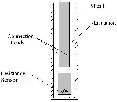
As shown in Figure 1, the RTD contains an outer sheath to prevent contamination from the surrounding medium. Ideally, this sheath is composed of material that efficiently conducts heat to the resistor, but resists degradation from heat or the surrounding medium.
The resistance sensor itself is responsible for the temperature measurement, as shown in the diagram. Sensors are most commonly composed of metals, such as platinum, nickel, or copper. The material chosen for the sensor determines the range of temperatures in which the RTD could be used. For example, platinum sensors, the most common type of resistor, have a range of approximately -200°C – 800°C. (A sample of the temperature ranges and resistances for the most common resistor metals is shown in Table 1). Connected to the sensor are two insulated connection leads. These leads continue to complete the resistor circuit.
| Element Metal | Temperature Range | Base Resistance | TCR(Ω/Ω/°C) |
|---|---|---|---|
| Copper | -100 – 260 °C | 10 Ω at 0 °C | 0.00427 |
| Nickel | -100 – 260 °C | 120 Ω at 0 °C | 0.00672 |
| Platinum | -260 – 800 °C | 100 Ω at 0 °C | 0.003916 |
There are 4 major categories of RTD sensors. There are carbon resistors, film thermometers, wire-wound thermometers and coil elements.
- Carbon resisters are the most commonly used. They are inexpensive and are accurate for low temperatures. They also are not affected by hysteresis or strain gauge effects. They are commonly used by researchers.
- Film thermometers have a very thin layer of metal, often platinum, on a plate. This layer is very small, on the micrometer scale. These thermometers have different strain gauge effects based on what the metal and plate are composed of. There are also stability problems that are dependent on the components used.
- In wire-wound thermometers the coil gives stability to the measurement. A larger diameter of the coil adds stability, but it also increases the amount the wire can expand which increases strain and drift. They have very good accuracy over a large temperature range.
- Coil elements are similar to wire-wound thermometers and have generally replaced them in all industrial applications. The coil is allowed to expand over large temperature ranges while still giving support. This allows for a large temperature range while decreasing the drift.
RTD Operation
Most traditional RTD operation is based upon a linear relationship between resistance and temperature, where the resistance increases with temperature. For this reason, most RTDs are made of platinum, which is linear over a greater range of temperatures and is resistant to corrosion. However, when determining a resistor material, factors such as temperature range, temperature sensitivity, response time, and durability should all be taken into consideration. Different materials have different ranges for each of these characteristics.
The principle behind RTDs is based upon the Callendar – Van Dusen equation shown in Equation \ref{1}, which relates the electrical resistance to the temperature in °C. This equation is merely a generic polynomial that takes form based upon experimental data from the specific RTD. This equation usually takes on a linear form since the coefficients of the higher-order variables (a2, a3, etc.) are relatively small.
\[R_{T}=R_{0}\left(1+a_{1} T+a_{2} T^{2}+a_{3} T^{3}+a_{4} T^{4}+\ldots+a_{n} T^{n}\right) \label{1} \]
RT: Resistance at temperature T, in ohms
R0: Resistance at temperature = 0°C, in ohms
an: Material’s resistance constant, in °Cn − 1
Another type of RTD is the thermistor, which operates based upon an exponential relationship between electrical resistance and temperature. Thermistors are primarily composed of semiconductors, and are usually used as fuses, or current-limiting devices. Thermistors have high thermal sensitivity but low temperature measuring ranges and are extremely non-linear. Instead of the Callendar - Van Dusen equation, the thermistor operates based upon the nonlinear equation, equation (2), shown in degrees K.
\[R_{T}=R_{0} \exp \left(b\left(\frac{1}{T}-\frac{1}{T_{0}}\right)\right) \label{2} \]
T0: Initial temperature, usually set at 298K
b: Material's temperature coefficient of resistance, in K
Errors associated with resistance thermometers will occur due to the individual or collective efforts of: defective insulation, contamination of the resistor, or insecure lead wire connections.
Thermocouples
Another temperature sensor often used in industry is the thermocouple. Among the various temperature sensors available, the thermocouple is the most widely used sensor. Similar to the RTD, the thermocouple provides an electrical measurement of temperature.
Thermocouple Structure
The thermocouple has a long, slender, rod-like shape, which allows it to be conveniently placed in small, tight places that would otherwise be difficult to reach. A schematic diagram of a typical thermocouple is shown in Figure 2.
As illustrated in Figure 2, the thermocouple contains an outer sheath, or thermowell. The thermowell protects the contents of the thermocouple from mechanical and chemical damage.
Within the thermowell lies two metal wires each consisting of different metals. Various combinations of materials are possible for these metal wires. Three common thermocouple material combinations used for moderate temperature measurements are the Platinum-Rhodium, Iron-Constantan, and Chromel-Alumel metal alloys. The metal alloys chosen for a thermocouple is based upon the emf value of the alloy pair at a given temperature. Sample emf values for the most common materials at various temperatures are shown in Table 2. For a given pair of materials, the two wires are connected at one end to form a junction. At the other end, the two wires are connected to a voltage measuring device. These ends of the wires are held at a different reference temperature.
| Alloy Type | Emf Value at 20 °C | Emf Value at 50 °C | Emf Value at 100 °C |
|---|---|---|---|
| Platinum-Rhodium | 0.113 mV | 0.299 mV | 0.646 mV |
| Iron-Constantan | 1.019 mV | 2.585 mV | 5.269 mV |
| Chromel-Alumel | 0.798 mV | 2.023 mV | 4.096 mV |
Various methods are used to maintain the reference temperature at a known, constant temperature. One method consists of placement of the reference junction within either an ice bath or oven maintained at a constant temperature. More commonly, the reference temperature is maintained electronically. Though not as stable as an ice bath, electronically controlled reference temperatures are more convenient for use. Reference temperatures could also be maintained through temperature compensation and zone boxes, which are regions of uniform temperature. The voltage difference across the reference junction is measured and sent to a computer, which then calculates the temperature with this data.
Thermocouple Operation
The main principle upon which the thermocouple function is based on is the difference in the conductivities of the two wire materials that the thermocouple is made of, at a given temperature. This conductivity difference increases at higher temperatures and conversely, the conductivity difference decreases at lower temperatures. This disparity results in the thermocouples being more efficient and useful at higher temperatures. Since the conductivity difference is small at lower temperatures and thus more difficult to detect, they are inefficient and highly unreliable at low temperatures.
The conductivity difference between the two wires, along with a temperature difference between the two junctions, creates an electrical current that flows through the thermocouple. The first junction point, which is the point at which the two wires are connected, is placed within the medium whose temperature is being measured. The second junction point is constantly held at a known reference temperature. When the temperature of the medium differs from the reference temperature, a current flows through the circuit. The strength of this current is based upon the temperature of the medium, the reference temperature, and the materials of the metal wires. Since the reference temperature and materials are known, the temperature of the medium can be determined from the current strength.
Error associated with the thermocouple occurs at lower temperatures due to the difficulty in detecting a difference in conductivities. Therefore, thermocouples are more commonly used at higher temperatures (above -125°C) because it is easier to detect differences in conductivities. Thermocouples are operable over a wide range of temperatures, from -200°C to 2320°C, which indicates its robustness and vast applications. Thermocouples operate over this wide range of temperatures, without needing a battery as a power source. It should be noted that, the wire insulation might wear out over time by heavy use, thus requiring periodical checks and maintenance to preserve the accuracy of the thermocouple.
To determine the temperature of the medium from the current strength, the emf or voltage values of the current and of the wire materials at the reference temperatures must be known. Often, the measured temperature can be found by using standard thermocouple tables. However, these tables are often referenced at 0°C. To correct for this different reference temperature, equation (3) can be used to calculate the temperature from a given current.
\[\xi_{T_{1}, T_{3}}=\xi_{T_{1}, T_{2}}+\xi_{T_{2}, T_{3}} \label{3} \]
 : emf of an alloy combination generated at two different temperatures
T1: temperature of the medium whose temperature is to be determined
T2: reference temperature of the thermocouple
T3: reference temperature of the standard thermocouple table, which in this case is 0°C
Once the emf between two alloys is calculated relative to a reference temperature when \(T_3\) is 0°C, the standard thermocouple table can be used to determine the temperature T1 of the medium. This temperature is usually automatically displayed on the thermocouple.
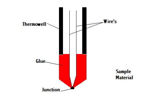
Apart from the common occurrence of the thermocouples being placed in the fluid to measure temperature change, thermocouples can be also embedded in solids with excellent results. This is highly effective while establishing the different thermal properties for a solid. The heat transfer to the thermocouple will now be in the form of conductive heat transfer. As a result, this setup would be very similar to heat conduction in series, since the thermocouple is almost always made from a different material then the actual solid. Such discrepancies depend on the manner in which the thermocouple is embedded in the solid and should be taken into account when the thermal properties are being calculated and analyzed. One example is shown in the photo below.
Laws for thermocouples
- Law of homogenous material: If all the wires and the thermocouple are made of the same material, temperature changes in the wiring do not affect the output voltage. Thus, need different materials to adequately reflect the temperature.
- Law of intermediate materials: The sum of all the thermoelectric forces in a circuit with a number of dissimilar materials at a uniform temperature is zero. This implies that if a third material is added at the same temperature, no net voltage is generated by the new material.
- Law of successive or intermediate temperatures: If two dissimilar homogeneous materials produce thermal emf1 when the junctions are at T1 and T2 and produce thermal emf2 when the junctions are at T2 and T3 , the emf generated when the junctions are at T1 and T3 will be emf1 + emf2 .
Application
- Steel industry: Monitor temperature and chemistry throughout the steel making process
- Heating appliance safety: Thermocouples in fail-safe mode are used in ovens and water heaters to detect if pilot flame is burning to prevent fire and health hazard
- Manufacturing: Used for testing prototype electrical and mechanical apparatus
- Process plants: Chemical production plants and refineries use computer programs to view the temperature at various locations. For this situation, a number of thermocouple leads are brought to a common reference block.
Pyrometers
Unlike the thermometer, RTD and the thermocouple, pyrometers (non-contact temperature sensors) measures the amount of heat radiated, rather than the amount of heat conducted and convected to the sensor. Various types of pyrometers, such as total radiation and photoelectric pyrometers, exist. Below is a schematic of an optical pyrometer in Figure 4.
These pyrometers differ in the type of radiation they measure. There are many factors that influence the amount of radiated heat detected, thus there are many assumptions that must be made regarding the emissivity, or the measure of the manner in which heat is radiated, of the object. These assumptions are based upon the manner in which heat is radiated as well as the geometry of the object. Because temperature is dependent on the emissivity of a body, these assumptions regarding the emissivity introduce uncertainties and inaccuracies in the temperature readings. Therefore, because of the error associated with them, pyrometers are not often used in industry.
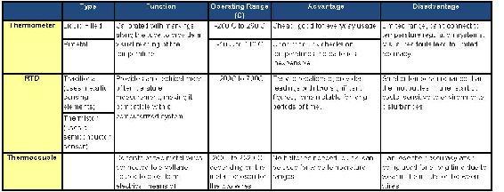
Table 3. Summary of Temperature Sensors
There are a few different types of pyrometers. There are optical and radiation pyrometers.
How Optical Pyrometers Work:
- Compares the color of visible light given off by the object with that of a electrically heated wire
- The wire can be preset to a certain temperature
- The wire can be manually adjusted to compare the two objects
How Radiation Pyrometers Work:
- This sensor works by measuring the radiation (infrared or visible light) that an object gives off
- The radiation heats a thermocouple in the pyrometer which in turn induces a current
- The larger the current induced, the higher the temperature is
Pyrometers are usually used at very high temperatures, but can be used at colder temperatures as well. There are lots of industrial applications to pyrometers. Plant operators can use pyrometers to get a sense of what temperature certain processes are running at. The downside to pyrometers is that they are not very accurate as thermocouples or RTD sensors are. This is because they rely on quantifying colors of light.
Temperature Regulators
Temperature regulators, also known as temperature control valves (TCVs), physically control, as well as measure, temperature. Temperature regulators are not capable of directly maintaining a set value; instead, they relate the load (in this case the valve opening) with the control (temperature measurement). These regulators are most useful when temperature is correlated to a flow of a substance. For example, a TCV may be used to control the temperature of an exothermic reaction that requires constant cooling. The TCV measures the temperature of the reaction and, based upon this temperature, either increases or decreases the flowrate of cooling fluid to adjust the temperature of the reaction. Similarly, the regulator could be used to adjust the flow amount of steam, which is typically used to heat a substance. Therefore, by adjusting flowrate, the regulator can indirectly adjust temperature of a given medium.
Regulator Structure
The structure of a typical thermal regulator consists of four main parts, as shown in Figure 3. The temperature detecting element, which in most cases is a temperature sensor, as described above, sends either an electrical or mechanical signal through the connector to the actuator. The actuator then uses this signal to act upon the power source, which determines the position of the valve. (This will be further described in the next section.)
Regulator Operation
The temperature regulator operates based upon a mechanical means of temperature control. As previously mentioned, the bulb of the regulator is typically filled with a heat conducting substance. Due to the thermal expansion properties of this substance, the substance expands as the temperature increases. This expansion causes a change in the pressure of the actuator, which correlates to the temperature of the medium. This pressure change repositions a valve on the regulator, which controls the flowrate of a coolant. The temperature of the medium is then altered by the change in the flowrate of this coolant.
Types of Temperature Regulators
Though all regulators have the same basic build and purpose, they exist in a variety of forms. In particular, these regulators vary in four primary ways: temperature detecting elements, temperature detector placement, actuator type, and valve type.
Temperature Detecting Elements
Most temperature regulation systems use thermocouples or RTDs as temperature sensing devices. (Described above) For these systems, the connector is a computer. The sensors send an electric signal to the computer, which calculates the temperature. The computer then compares the temperature measured by the sensor to a programmed set-point temperature, thus determining the required pressure in the actuator. The pressure in the actuator changes position of the power source (diaphragm or bellows), which consequently changes the flowrate through the valve.
Some temperature regulation systems use a filled bulb as a temperature sensor. Based on the thermal expansion properties of the material within the bulb, the material expands as the temperature increases. This expansion causes a change in the pressure of the actuator. The pressure change actuator then repositions power source. Again, the change in the power source changes the flowrate through the valve.
Temperature regulation systems using thermocouples or RTDs as temperature sensing devices are much more common than regulation systems using filled bulbs.
Temperature Detector Placement: Internal and Remote Detection
Temperature detection can be done with internal or remote elements. For internal temperature detectors, the thermal actuator and temperature detector are located entirely within the valve. For remote temperature detectors, the primary temperature detecting element is separate from the actuator and valve, and is connected to the actuator with either electrical wiring or capillary tubing, depending on the mechanism of the temperature sensor. Remote temperature detectors are more common, as internal temperature detectors are limited in use. Internal temperature detectors can only measure the temperature of the fluid flowing through the valve and not the temperature of the process.
Actuator Type: Thermal Systems
There are four main categories of thermal actuators used in temperature regulators. Thermal actuators produce power and work, proportional to the measured temperature of the process, on the power source. Actuator types include the vapor-filled system, the liquid-filled system, the hot chamber system, and the fusion-type or wax-filled system. Of all the thermal systems mentioned, liquid-filled systems are the most common, because they relate temperature and pressure change in a linear fashion.
Vapor-Filled Systems
In the vapor-filled system, the thermal actuator is partially filled with a volatile liquid. As the temperature of the sensor increases, the vapor pressure of the liquid also increases. This increases the pressure on the power source, and adjusts the flowrate through the valve.
Liquid-Filled Systems
In liquid-filled systems, the thermal actuator is filled with a chemically stable liquid, such as a hydrocarbon. As the temperature increases, the liquid expands, which produces a force on the power source.
Hot Chamber Systems
In hot chamber systems, the thermal actuator is partially filled with a volatile fluid. An increase in temperature of the system forces some of this fluid into the power unit, where the heat of the unit causes this liquid to turn into a superheated vapor. The pressure increase produces a force on the power source.
Fusion-Type (Wax-Filled) Systems
Of all the systems mentioned, the fusion-type system is the least common. In the fusion-type system, the thermal actuator is filled with special waxes such as hydrocarbons, silicones, and natural waxes. The wax contains large amounts of copper, which increases the heat-transfer quality of the wax. As temperature increases, the wax expands, producing a force that repositions the power source.
Valve Type: Direct and Pilot Actuated
The two main types of valves used in thermal regulators are the direct and pilot actuated valves. In all such thermal regulators, there is a power source (such as bellows and diaphragms) that provides the force required to reposition the valve to control the temperature. These power sources rely on a change in the pressure of the actuator in order to properly regulate temperature. In direct-actuated TCVs, this power unit is directly connected to the valve, which provides the force required to open and close the valve. In pilot-actuated TCVs, the thermal actuator moves a pilot valve, which then transfers energy in the form of pressure to a piston, which then provides the work necessary to reposition the main valve.
Direct-actuated TCVs are often much simpler in structure than pilot-actuated TCVs, and therefore they are also much cheaper. In addition, they respond better to smaller changes in temperature and more accurately reflect the temperature of the medium. Thus, if the exact temperature of the system is essential to ensure correct operation, a direct-actuated TCV should be used. Pilot-actuated TCVs usually have much smaller temperature sensing devices, a faster response time, and the ability withstand much higher pressures through the regulating valve. Therefore, at high pressures or rapid temperature changes, a pilot-actuated TCV should be used.
Resistance Temperature Detector Example
Note: This example problem has been made up for demonstration purposes.
A newly hired chemical engineer at Hypothetical Industries is responsible for monitoring and maintaining temperatures for one of the company’s exothermic reactions. The process uses a platinum resistor thermometer to measure the temperature of the process, the properties of which are given below. The reaction’s ideal range is between 250°C – 350°C. Below 250°C, the catalyst ceases to function, and above 350 °C, it can be classified as a runaway reaction. The engineer can control steam and cooling water to regulate the process temperature.
Describe what changes the engineer should make to either the flowrate of the coolant or the steam to keep the system functioning optimally.
Case I: RT = 25ohms
Case II: RT = 13.9ohms
Case III: RT = 19.4ohms
GIVEN DATA:
RT = R0(1 + a1T + a2T2)
R0 = 10 ohms
a1 = 3.91x10 − 3(°C)
a2 = − 6.72x10 − 8(°C − 2)
Solution:
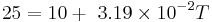
Substitute the given value of RT for each of the 3 cases into the mathematical calculations below to get the answers, we have worked out Case I with the corresponding numbers below.
Case I:
1. Factor R0 throughout the right side of the equation.
2. Subtract RT from both sides of the equation.
3. Solve for T using the quadratic equation.


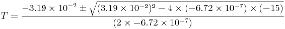

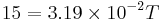
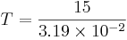
ALTERNATE Solution:
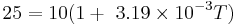
1. Since the constant a2 is so small (x10 − 7) we can just neglect that term.
2. Now the problem is just a simple linear equation, which can be solved by isolating T on one side of the equation.

AnswerS:
Case I. The engineer should start flowing cooling water into the reaction process because the temperature is ~ 500°C which is
above the appropriate range.
Case II. The engineer should increase steam feed to the reaction process because the temperature is ~ 125°C which is below
the appropriate range.
Case III. The engineer does not have to do anything because the temperature is in the appropriate range ~ 300°C.
You are a chemical engineer at Hypothetical Industries and you are responsible for monitoring and regulating the temperature for one of the company’s reactions. Determine which temperature sensor should be used to optimally measure and regulate the reaction’s temperature in each of the following situations.
- Case I. T=900°C
- Case II. T=500°C but sensor location in a large continuous reactor makes it difficult to repair
- Case III. T=50°C and you are estimating the current temperature of a lab scale reaction
Solution
Case I. We know that the reaction occurs at 900°C. Taking this optimal temperature as the only necessary parameters, the temperature sensor would be a thermocouple. The temperature is outside of the range for resistance thermometers. Regular thermometers do not send electric signals; therefore they can not be used for this process.
Case II. Although this temperature is within the operating ranges of both thermocouples and RTDs, since the sensor may not be readily accesible for repair, we must use an RTD because thermocouples lose accuracy after extended usage.
Case III. Since the temperature is within the range of all three sensors, and we only need a rough estimate of temperature, we can use a thermometer which will be much less costly than the alternative sensors.
References
- Dougherty, E.P. ,Temperature Control Principles for Process Engineers, Hanser Publishers, 1993 ISBN 0344615980
- Liptak,B.G. ,Instrument Engineer's Handbook, 4th Edition,Volume 2. Taylor and Francis Group,2005 ISBN 0849310814
- Perry,R.H. ,Perry's Chemical Engineer's Handbook, 7th Edition, McGraw-Hill,1997 ISBN 0070498415
- Richardson,J.F. and Peacock,D.G. ,Chemical Engineering, 3rd Edition,Volume 3. Butterworth-Heinemann,1994 ISBN 0080410030
- Moffat,R.J. ,Notes on Using Thermocouples, 1997
- Error! Hyperlink reference not valid.
- Pyrosales
- Cole parmer Suppliers
- Temperature.com
Contributors and Attributions
- Authors: (14 September 2006) Ardemis Boghossian, James Brown, Sara Zak
- Stewards: (11 September 2007) Arthur L. Edge III, Kathryn Meintel, Renu Rao, Kaveh Saba