
11.1: Feedback Control
- Page ID
- 22644

Introduction
There are many different control mechanisms that can be used, both in everyday life and in chemical engineering applications. Two broad control schemes, both of which encompass each other are feedback control and feed-forward control. Feedback control is a control mechanism that uses information from measurements to manipulate a variable to achieve the desired result. Feed-forward control, also called anticipative control, is a control mechanism that predicts the effects of measured disturbances and takes corrective action to achieve the desired result. The focus of this article is to explain application, advantages, and disadvantages of feedback control.
Feedback control is employed in a wide variety of situations in everyday life, from simple home thermostats that maintain a specified temperature, to complex devices that maintain the position of communication satellites. Feedback control also occurs in natural situations, such as the regulation of blood-sugar levels in the body. Feedback control was even used more than 2,000 years ago by the Greeks, who manufactured such systems as the float valve which regulated water level. Today, this same idea is used to control water levels in boilers and reservoirs.
Feedback Control
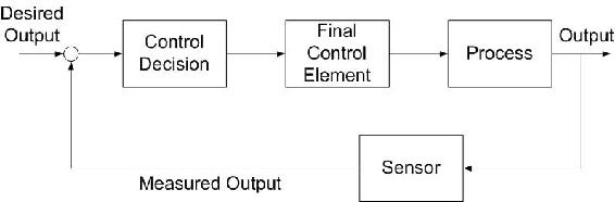
In feedback control, the variable being controlled is measured and compared with a target value. This difference between the actual and desired value is called the error. Feedback control manipulates an input to the system to minimize this error. Figure \(\PageIndex{1}\) shows an overview of a basic feedback control loop. The error in the system would be the Output - Desired Output. Feedback control reacts to the system and works to minimize this error. The desired output is generally entered into the system through a user interface. The output of the system is measured (by a flow meter, thermometer or similar instrument) and the difference is calculated. This difference is used to control the system inputs to reduce the error in the system.
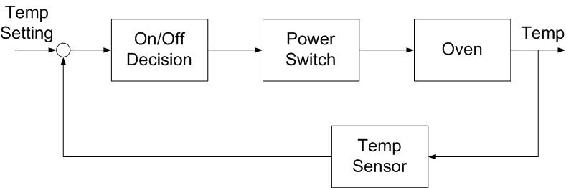
To understand the principle of feedback control, consider Figure \(\PageIndex{2}\) In order to bake cookies, one has to preheat an electric oven to 350°F. After setting the desired temperature, a sensor takes a reading inside the oven. If the oven is below the set temperature, a signal is sent to the heater to power on until the oven heats to the desired temperature. In this example, the variable to be controlled (oven temperature) is measured and determines how the input variable (heat into oven) should be manipulated to reach the desired value.
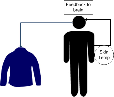
Feedback control can also be demonstrated with human behavior. For example, if a person goes outside in Michigan winter, he or she will experience a temperature drop in the skin. The brain (controller) receives this signal and generates a motor action to put on a jacket. This minimizes the discrepancy between the skin temperature and the physiological set point in the person. The example is illustrated below:
There are two types of feedback control: negative and positive. Negative feedback is the most useful control type since it typically helps a system converge toward an equilibrium state. On the other hand, positive feedback can lead a system away from an equilibrium state thus rendering it unstable, even potentially producing unexpected results. Unless stated explicitly, the term feedback control most often refers to negative feedback.
Negative Feedback
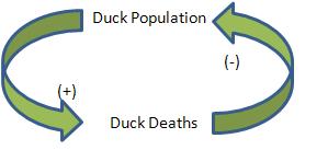
By definition, negative feedback is when a change (increase/decrease) in some variable results in an opposite change (decrease/increase) in a second variable. This is demonstrated in Figure \(\PageIndex{3}\) where a loop represents a variation toward a plus that triggers a correction toward the minus, and vice versa. Negative feedback leads to a tight control situation whereby the corrective action taken by the controller forces the controlled variable toward the set point, thus leading the system to oscillate around equilibrium.
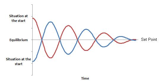
Figure \(\PageIndex{4}\) shows the negative feedback mechanism between Duck Population and Duck Death Rate. For a given flock, we say that if the death rate increases, the duck flock will decrease. On the contrary, if the duck flock increases, the death rate of the flock will decrease.
Positive Feedback
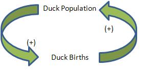
As opposed to negative feedback, positive feedback is when a change (increase/decrease) in some variable results in a subsequently similar change (increase/decrease) in a second variable. In some cases, positive feedback leads to an undesirable behavior whereby the system diverges away from equilibrium. This can cause the system to either run away toward infinity, risking an expansion or even an explosion, or run away toward zero, which leads to a total blocking of activities (Figure \(\PageIndex{5}\)).
Figure \(\PageIndex{6}\) shows the feedback mechanism responsible for the growth of a duck flock via births. In this example, we consider two system variables: Duck Births and Ducks Population. For a given flock, we state that if the birth rate increases, the duck flock will increase. Similarly, if the duck flock increases, the birth rate of the flock will increase.
Applications
Control mechanisms are used to achieve a desired output or operating condition. More specifically, feedback control is a useful mechanism in numerous applications across many engineering fields. In chemical engineering, feedback control is commonly used to manipulate and stabilize the conditions of a CSTR. Figure \(\PageIndex{7}\) shows how feedback control can be effectively used to stabilize the concentrations of reactants in a CSTR by adjusting the flow rates.
CSTR with Feedback Control
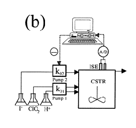
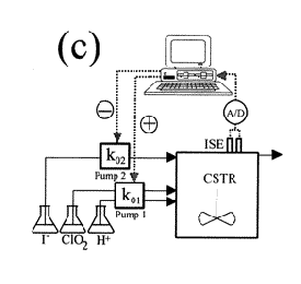
Several types of feedback control can be used to manipulate the conditions in a CSTR: positive feedback, negative feedback, or a combination of both. Figure \(\PageIndex{7}\) illustrates each of these possible situations. As depicted below, each CSTR is equipped with two electrodes that measure the voltage of the solution contained inside the reactor. A computer adjusts the flow rates of the pump(s) in response to any changes in the voltage.
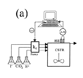
- (a) All of the reagents are pumped into the reactor by the same pump. The flow rate through the pump is adjusted constantly by a negative feedback mechanism; when level of the iodide solution is low, the computer detects the insufficiency and increases the flow rate of all the reactants.
- (b) The iodide solution is pumped into the reactor by one pump, while the other two reactants are pumped in at a constant flow rate. The flow rate of the iodine solution is controlled by a negative feedback mechanism; when the computer detects an insufficient amount of iodine in the CSTR, it signals the pump. The flow rate of iodine into the CSTR is therefore increased.
- (c) Two pumps are used to feed the reactor: one pump for the iodine solution and one for the ClO2 and H+ solutions. The flow of the iodine solution is controlled by a negative feedback mechanism; if the computer detects an iodine deficiency, it signals Pump 2 to increase the flow rate of the iodide solution. The flow rate of the ClO2 and H+ solutions is controlled by a positive feedback mechanism; if the computer detects an iodide deficiency, it will signal Pump 1 to decrease the flow rates of ClO2 and H+,thereby increasing the concentraion of iodide.
It is easy to see that by combining feedback controls, such as in Figure \(\PageIndex{1c}\), output concentrations and operating conditions can be maintained at the desired state much more effectively than by only using one type of feedback control.
Advantages and Disadvantages
The unique architecture of the feedback control provides for many advantages and disadvantages. It is important to look at the exact application the control will be used for before determining which type of control will be the best choice (see Cascade Control Systemsand Feed Forward Control).
Advantages: The advantages of feedback control lie in the fact that the feedback control obtains data at the process output. Because of this, the control takes into account unforeseen disturbances such as frictional and pressure losses. Feedback control architecture ensures the desired performance by altering the inputs immediately once deviations are observed regardless of what caused the disturbance. An additional advantage of feedback control is that by analyzing the output of a system, unstable processes may be stabilized. Feedback controls do not require detailed knowledge of the system and, in particular, do not require a mathematical model of the process. Feedback controls can be easily duplicated from one system to another. A feedback control system consists of five basic components: (1) input, (2) process being controlled, (3) output, (4) sensing elements, and (5) controller and actuating devices. A final advantage of feedback control stems from the ability to track the process output and, thus, track the system’s overall performance.
Disadvantages: Time lag in a system causes the main disadvantage of feedback control. With feedback control, a process deviation occurring near the beginning of the process will not be recognized until the process output. The feedback control will then have to adjust the process inputs in order to correct this deviation. This results in the possibility of substantial deviation throughout the entire process. The system could possibly miss process output disturbance and the error could continue without adjustment. Generally, feedback controllers only take input from one sensor. This may be inefficient if there is a more direct way to control a system using multiple sensors. Operator intervention is generally required when a feedback controller proves unable to maintain stable closed-loop control. Because the control responds to the perturbation after its occurrence, perfect control of the system is theoretically impossible. Finally, feedback control does not take predictive control action towards the effects of known disturbances.
Closed Loop Control versus Open Loop Control
Although there are various types of controllers, most of them can be grouped into one of the two broad categories: closed loop and open loop controllers. The subsections below summarize the differentiation.
Closed Loop System
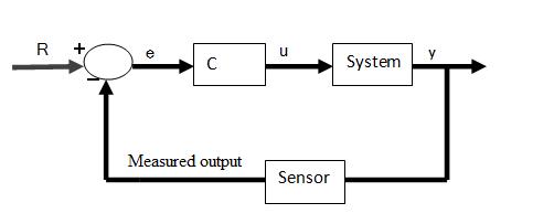
In a closed loop control system, the input variable is adjusted by the controller in order to minimize the error between the measured output variable and its set point. This control design is synonymous to feedback control, in which the deviations between the measured variable and a set point are fed back to the controller to generate appropriate control actions.The controller C takes the difference e between ther reference r and the output to change the inputs u to the system. This is shown in figure below. The output of the system y is fed back to the sensor, and the measured outputs go to the reference value
Open Loop System
On the other hand, any control system that does not use feedback information to adjust the process is classified as open loop control. In open loop control, the controller takes in one or several measured variables to generate control actions based on existing equations or models. Consider a CSTR reactor that needs to maintain a set reaction temperature by means of steam flow (Figure \(\PageIndex{8}\)): A temperature sensor measures the product temperature, and this information is sent to a computer for processing. But instead of outputting a valve setting by using the error in temperature, the computer (controller) simply plugs the information into a predetermined equation to reach output valve setting. In other words, the valve setting is simply a function of product temperature.
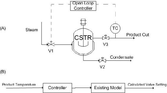
Note that the open loop controller only uses the current state of the measured variable (product temperature) and a model to generate its control output (valve setting), as opposed to monitoring errors that have already taken place. As the result, the quality of the control system depends entirely upon the accuracy of the implemented model, which is challenging to develop. For this reason, feedback, or closed loop, controllers are generally recognized as the more reliable control system.
Short Summary on Closed and Open Loop Controllers
- Feedback Controller = Closed Loop Controller
- Non-Feedback Controller = Open Loop Controller
Your company is designing a plant to produce biodiesel. Several of the unit processes require heated water that is under tight temperature control. The desired temperature of the water is 65°C ± 1°C. To accomplish this, steam will be used in a shell and tube heat exchanger to heat the incoming water.
A member on the project team suggests the following feed forward control system to regulate the temperature of the water stream. Temperature and flow rate data for the incoming steam and water streams will be used along with energy balance calculations to determine the flow rate of steam required to keep the exiting water stream at the appropriate temperature.
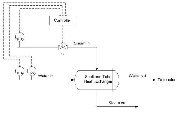
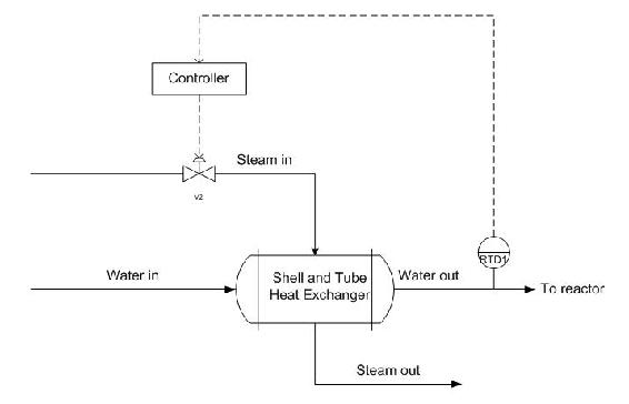
You on the other hand suggest a feedback control system. Place the appropriate sensors, actuators, and controllers to implement a feedback control system that will allow for the control of the exiting water temperature. What are some of the advantages and disadvantages of using a feedback control system over a feed forward control system?
Solution
In the feedback control system, the temperature of the variable to be controlled is measured directly. If the exiting water temperature is too high, the controller will decrease the amount of steam entering the shell side of the heat exchanger. Likewise, if the exiting water temperature is too low, the controller will increase the amount of steam entering the shell side of the heat exchanger. This is an example of negative feedback at work to keep the exiting temperature at the setpoint.
Advantages
- Effective regardless of the origin of the disturbance.
- Relatively simple to implement. A mathematical model of the exiting water temperature is not needed.
Disadvantages
- Corrective action taken only after there is a deviation in the output from the set point.
- Can cause instability if incorrectly tuned
Of the following two scenarios, which would be the best to use a feedback control?
- Solution
- A feed-forward control or feed-forward/feedback system would most appropriate for the first scenario. In this situation, it is critical that the pH of the waste stream not drop below the setpoint of pH 6. It is also desirable to minimize the use of lime, since this reduces the cost of the waste treatment. Therefore very tight process controls are desired, for which a feed-forward or feed forward/feedback system would be most appropriate. A feed-forward system can adjust to changes in inputs before they cause deviations in the output stream. Additionally, since there are important fluctuations two process inputs (pH variations in both the lime slurry and the acidic waste), feed-forward controls would be favored over feedback control.
- A feedback control would be most useful for the second scenario. There is only one monitored variable (concentration of reduced wine) and only one manipulated variable (steam). Since minor fluctuations about the wine concentration set point are not critical, the performance of a typical feedback control system would be acceptable. It would be hard to implement a feed-forward control system since the concentration of the wine feed to the evaporator may fluctuate and is not monitored.
Using a shell and tube heat exchanger, a fuel stream is pre-heated using a steam stream from the utilities part of the plant. The plant is located in Ann Arbor, Michigan. Originally, a feedback controller is implemented to control the amount of steam coming into the shell and tube exchanger based on the temperature of the flow out of the exchanger. This is depicted below.
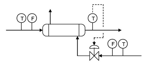
Upon implementation in the process, it was found that the feed temperature was not the only factor in the variance of the outlet stream. Because the plant is operated in Michigan, the steam temperature varies between seasons, colder in the winter and warmer in the summer. Propose a control scheme to account for both of these variances.
Solution
Here a cascade control scheme would be optimal to control the outlet temperature of the stream to a desired temperature, not just a feedback controller. The scheme is depicted below.
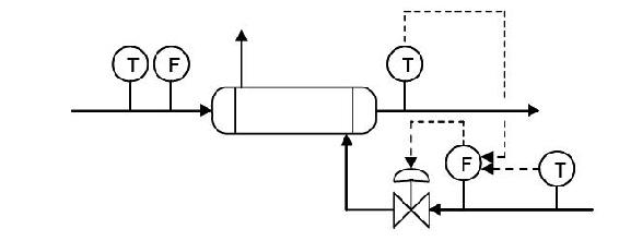
The feedback control previously used to control the system is still implemented, however it is now reporting to the flow controller before the steam control valve. Also, there is a temperature controller now incorporated in the control scheme. This is a feed forward controller that also controls the flow controller for the steam control valve. Thus the primary control loops, the feed forward and feedback control loops, comprise the secondary control loop in the cascade control. This incorporates both the temperature of the incoming feed stream, which is controlled by feedback control via the temperature sensor after the exchanger. This is because the temperature of the outlet stream would vary with the temperature of the inlet stream if the steam stream were not accounted for. But accounting for the temperature of the steam stream, via a feed forward controller that is based on a temperature sensor before the control valve, will give a better approximation and more control over the temperature of the outlet stream. This is also a very good example of combining several control architectures and how they function in a real-world application, and why a feedback controller in not necessarily the most accurate control.
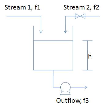
A blending system is used to mix a process stream (Stream 1, pure A) with liquid catalyst (Stream 2, pure B). The mixture then flows into a reactor. The flowrate of stream 1 (f1) can vary but it is possible to manipulate the flowrate of stream 2 (f2). The outflow rate from the reactor (f3) also can be manipulated via a pump. The level in the measures by a level transmitter that sends its signal to a level controller. All three flow rates can be measured, but measuring the composition of the streams is impossible. In order to control the level of the tank, and engineer has two options:
- manipulate f2 while holding f3 constant
- manipulate f3 while holding f2 constant
Could method (i) utilize feedforward or feedback control of the level? If so, explain how it can be done.
Could method (ii) utilize feedforward or feedback control of the level? If so, explain how it can be done.
Solution
For configuration (i)
- Feedback: If you measure h, when it goes up, you can reduce f2, and when it goes down, you can increase f2
- Feedforward: If you measure f1, when it goes up, you can reduce f2, and and when it goes down, you can increase f2. You are indirectly controlling h due to the mass balance.
For configuration (ii)
- Feedback: If you measure h, when it goes up, you can increase f3, and when it goes down, you can decrease f3.
- Feedforward: If you measure f1, when it goes up, you can reduce f3, and when it goes down, you can reduce f3.
This problem was meant to explore different strategies for both feedback and feedforward control configurations. Additionally, it demonstrates how controlling the manipulated variables (either f2 for configuration (i) or f3 for configuration (ii)) affects the desired outcome (maintaining consistent tank height).
References
- Lee, P., Newell, R., Cameron, I.(1998).Process Control and Management, London:Blackie Academic & Professional. ISBN 0-7514-0457-8
- Marlin, T.(2000). Process Control: Designing Processes and Control Systems for Dynamic Performance, Boston:Mcgraw Hill. ISBN 0-07-039362-1
- Palazoglu, A., Romagnoli, J.(2006).Introduction to Process Control, Boca Raton:Taylor & Francis. ISBN 0-8493-3696-9
- Perry,R.H.(1997). Perry's Chemical Engineer's Handbook, 7th Edition, McGraw-Hill. ISBN 978-0-07-049841-9
- National Lime Association Article. Using Lime for Acid Neutralization. September 2000.
- MIT Open Courseware. (2006). "Lesson 8: Cascade and Feedforward Control Schemes," [1]
Contributors and Attributions
- Authors: Eddy Kim, Bing Liu, Tyler Roehm, Samah Tout
- Stewards: Gillian Berberich, Katie Feldt, Christopher Mark, Jason Wong
- Cara Canady, David Carpenter, Che Martinez, Jeremy Minty, Bradley Novak