
11.3: Cascade Control
- Page ID
- 22509

Introduction
In the previous chapters, only single input, single output (SISO) systems are discussed. SISO involves a single loop control that uses only one measured signal (input). This signal is then compared to a set point of the control variable (output) before being sent to an actuator (i.e. pump or valve) that adjusts accordingly to meet the set point. Cascade controls, in contrast, make use of multiple control loops that involve multiple signals for one manipulated variable. Utilizing cascade controls can allow a system to be more responsive to disturbances.
Before venturing further into the topic of cascade controls, the terms 'manipulated variables', 'measured variables' and 'control variables' should be clarified. The definitions of these terms commonly found in literature are often interchangeable; but, they typically refer to either the input or output signal. For the purpose of this article, 'control variables' will refer to inputs like flow rates, pressure readings, and temperature readings. 'Manipulated variables' and 'measured variables' will refer to the output signals which are sent to the actuator.
The simplest cascade control scheme involves two control loops that use two measurement signals to control one primary variable. In such a control system, the output of the primary controller determines the set point for the secondary controller. The output of the secondary controller is used to adjust the control variable. Generally, the secondary controller changes quickly while the primary controller changes slowly. Once cascade control is implemented, disturbances from rapid changes of the secondary controller will not affect the primary controller.
Cascade Control
To illustrate how cascade control works and why it is used, a typical control system will be analyzed. This control system is one that is used to adjust the amount of steam used to heat up a fluid stream in a heat exchanger. Then an alternative cascade control system for the same process will be developed and compared to the typical single loop control. The figure below shows the performance of cascade control vs. single-loop control in CST heater
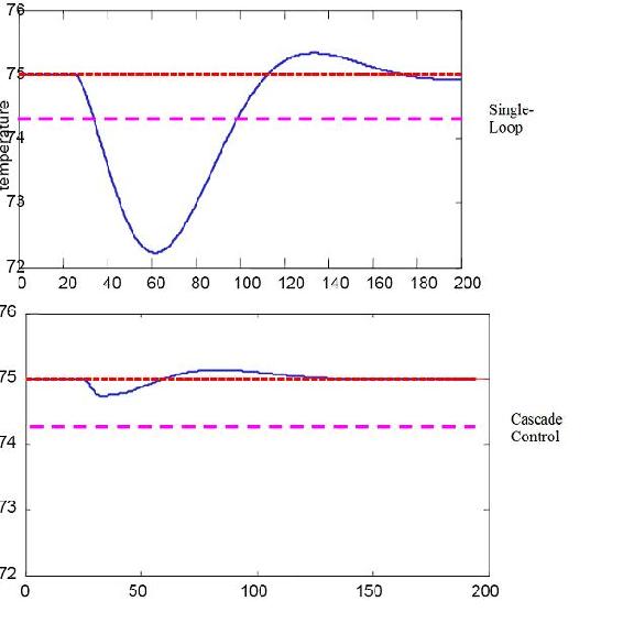
Cascade control gives a much better performance because the disturbance in the flow is quickly corrected
Example of Cascade Control
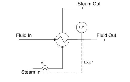
Figure 1. Single loop control for a heat exchanger
In the above process, the fluid is to be heated up to a certain temperature by the steam. This process is controlled by a temperature controller (TC1) which measures the temperature of the exiting fluid and then adjusts the valve (V1) to correct the amount of steam needed by the heat exchanger to maintain the specified temperature. Figure 2 shows the flow of information to and from the temperature controller.
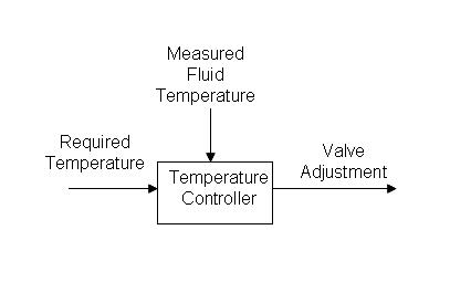
Figure 2. Flow of information when single loop feedback control is used for a heat exchanger
Initially, this process seems sufficient. However, the above control system works on the assumption that a constant flow of steam is available and that the steam to the heat exchanger is solely dependent on opening the valve to varying degrees. If the flow rate of the steam supply changes (i.e. pipeline leakage, clogging, drop in boiler power), the controller will not be aware of it. The controller opens the valve to the same degree expecting to get a certain flow rate of steam but will in fact be getting less than expected. The single loop control system will be unable to effectively maintain the fluid at the required temperature.
Implementing cascade control will allow us to correct for fluctuations in the flow rate of the steam going into the heat exchanger as an inner part of a grander scheme to control the temperature of the process fluid coming out of the heat exchanger. A basic cascade control uses two control loops; in the case presented below (see Figure 3), one loop (the outer loop, or master loop, or primary loop) consists of TC1 reading the fluid out temperature, comparing it to TC1set (which will not change in this example) and changing FC1set accordingly. The other loop (the inner loop, or slave loop, or secondary loop) consists of FC1 reading the steam flow, comparing it to FC1set (which is controlled by the outer loop as explained above), and changing the valve opening as necessary.
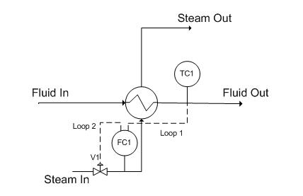
Figure 3. Cascade control for a heat exchanger
The main reason to use cascade control in this system is that the temperature has to be maintained at a specific value. The valve position does not directly affect the temperature (consider an upset in the stream input; the flow rate will be lower at the same valve setting). Thus, the steam flow rate is the variable that is required to maintain the process temperature.
The inner loop is chosen to be the inner loop because it is prone to higher frequency variation. The rationale behind this example is that the steam in flow can fluctuate, and if this happens, the flow measured by FC1 will change faster than the temperature measured by TC1, since it will take a finite amount of time for heat transfer to occur through the heat exchanger. Since the steam flow measured by FC1 changes at higher frequency, we chose this to be the inner loop. This way, FC1 can control the fluctuations in flow by opening and closing the valve, and TC1 can control the fluctuations in temperature by increasing or decreasing FC1set .
Thus, the cascade control uses two inputs to control the valve and allows the system to adjust to both variable fluid flow and steam flow rates. The flow of information is shown in figure 4.
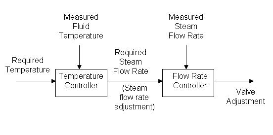
Figure 4. Flow of information when cascade control is used for a heat exchanger
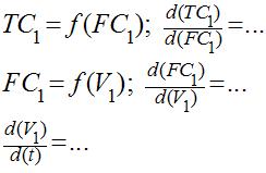
In order to accomplish this, relationships between the primary and secondary loops (see definitions below) must be defined. Generally, the primary loop is a function of the secondary loop. A possible example of such relations is:
Primary and Secondary Loops
In Figure 3, there are two separate loops. Loop 1 is known as the primary loop, outer loop, or the master, whereas loop 2 is known as the secondary loop, inner loop, or the slave. To identify the primary and secondary loops, one must identify the control variable and the manipulated variable. In this case, the control variable is the temperature and the reference variable is the steam flow rate. Hence, the primary loop (loop 1) involves the control variable and the secondary loop (loop 2) involves the reference variable. The information flow for a two loop cascade control system will typically be as shown in Figure 5. Please note that the user sets the set point for loop 1 while the primary controller sets the set point for loop 2.
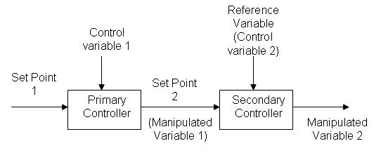
Figure 5: Information flow of a two loop cascade control
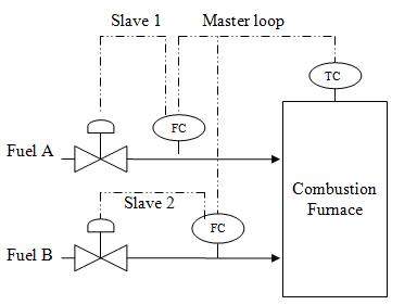
In addition to this common architecture, cascade control can have multiple secondary loops; however, there is still one primary loop and a main controlled variable. Unfortunately, with multiple inner loops, tuning the PID becomes even more challenging, making this type of cascade less common. The secondary loops can be either independent of each other, or dependent on each other, in which case each secondary loop affects the set point of the other secondary loop. When tuning such controller, the inner most loop should be tuned first. The loop that manipulates the set point of the inner-most loop should be tuned next and so for. The figure below shows an example of using two secondary loops, independent of each other, in a fuel combustion plant. In this combustion furnace, the master controller controls the temperature in the furnace by changing the set point for the flow of fuels A and B. The secondary loops correspond to the change in the set point for the flow, by opening or closing the valves for each fuel.
Cascade control is generally useful when
- A system error affects the primary control variable only after a long period of time as it propagates through dead time and lag time.
- A system has long dead times and long lag times.
- Multiple measurements with only one control variable are required for better response to a disturbance of a system.
- Variance occurs in multiple streams
General Cascade Control Schematic
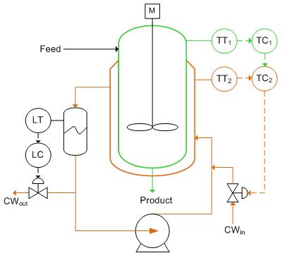
The reactor below needs to be cooled during continuous-feed operation of an exothermic reaction. The reactor has been equipped with a cooling water jacket with the water flow rate being controlled by cold water valve. This valve is controlled by two separate temperature controllers. An “inner-loop” or “slave” (highlighted in orange) temperature transmitter communicates to the slave controller the measurement of the temperature of the jacket. The “outer-loop” or “master” (green) temperature controller uses a master temperature transmitter to measure the temperature of the product within the reactor. The output from the slave controller is fed into the master controller and used to adjust the cold water valve accordingly.
The cascade control loop used to control the reactor temperature can be generalized with the schematic below. We will use this main diagram to go through the formal derivation of the equations describing the behavior of the system when there are changes in the loads U1 and U2 but with no change in the set point, R1(t). The general equations derived below can be used to model any type of process (first, second, third order differential equations, ect.) and use any type of control mechanism (proportional-only, PI, PD, or PID control). See wiki pages titled “first-order differential equations” and “P, I, D, PI, PD, PID Control” for more details.
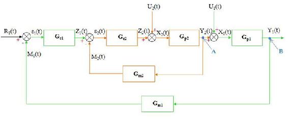
Step 1: Write down all the equations for each stage of the control loop
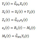
Master Loop
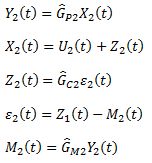
Slave Loop
Gp1 and Gp2 are the process operators and are usually of the form:
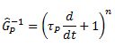
Where n is a natural number.
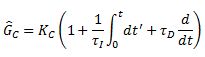
Gc1 and Gc2 are the control operators and depend on the type of controller used. For PID controllers, they would be:
Gm1 and Gm2 are the measurement operators and usually are just equal to 1. Note that there are no equations for the "intersections" A and B shown on the diagram.
Step 2: Simplify the equations for the slave loop
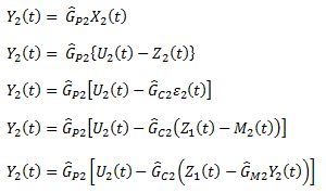
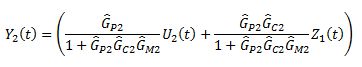
Solve for Y2(t)
Step 3: Simplify the equations for the master loop
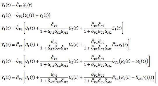
Solve for Y1(t)
(Note: here the G's are written as operators rather than Laplace transforms, and as such they shouldn't be divided. Thus, expressions in the denominator should be interpreted as inverse operators in the numerator.)
Conditions for Cascade Control
In order to have a smooth flow of information throughout the control system, a hierarchy of information must be maintained. In a double loop cascade system, the action of the secondary loop on the process should be faster than that of the primary loop. This ensures that the changes made by the primary output will be reflected quickly in the process and observed when the primary control variable is next measured. This hierarchy of information can be preserved by applying the following conditions when setting up the cascade controls.
- There must be a clear relationship between the measured variables of the primary and secondary loops.
- The secondary loop must have influence over the primary loop.
- Response period of the primary loop has to be at least 4 times larger than the response period of the secondary loop.
- The major disturbance to the system should act in the primary loop.
- The primary loop should be able to have a large gain, Kc.
Cascade control is best when the inner loop is controlling something that happens at fairly high frequency. Cascade control is designed to allow the master controller to respond to slow changes in the system, while the slave controller controls disturbances that happen quickly. If set up in reverse order, there will be a large propagation of error. Hence, it is important to maintain the hierarchy of information. In summary, the master controller responds to SLOW changes in the system, while the slave controller responds to the high frequency, or FAST changes in the system. This also requires that the inner control scheme be tuned TIGHTLY so error is not allowed to build. Commonly, the inner loops controls a flow controller, which will reduce the effect of changes such as fluctuations in steam pressure.
Cascade Control Design Considerations
Open Loop and Closed Loop
Although cascade control generally incorporates information from several secondary loops, the system overall does not automatically become a closed loop or an open loop process. For a cascade control to be open loop, all control loops in the system should be open loop in nature. On the other hand, if any of the control loops in the system is feedback-based, the system overall is considered as closed loop. This is due to the fact that the system is getting some sort of feedback, no matter how little the “fedback” variable influences the system.
Cascade with Feed-Forward and Feedback Controls
Cascade controllers have a distinct advantage over other kinds of controller due to its ability to combine both feedback and feed-forward controls. While feed-forward loops have the potential to adjust the controlled variables to the ideal states, the feedback loops in a mixed system check deviations to make sure the system is on track. The figure below is an example of a mixed cascade control:
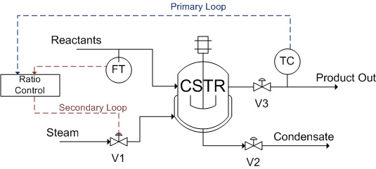
An endothermic reaction takes place in a jacketed CSTR, in which the reactor is heated by steam. A reactant stream feeds into the CSTR, which serves as the wild stream for the ratio controller to predict a required steam flow rate (feed-forward). On the product stream side, a temperature controller manipulates the ratio setting of the ratio controller in order to minimize the product temperature errors (feedback). The temperature controller is the primary loop, whereas the ratio controller is the secondary loop.
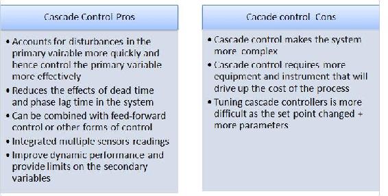
Advantages and Disadvantages of Cascade Control
The following table shows a list of cascade control pros and cons:
Starting up a Cascade System
A cascade system needs to be set up properly in order to function. The inner loop should be tuned before the outer loop. The following are the suggested steps for starting up a cascade system (both controllers start in automatic mode):
- Place the primary controller in manual mode. This will break the cascade and isolate the secondary controller so that it can be tuned.
- Tune the secondary controller as if it were the only control loop present.
- Return the secondary controller to the remote set point and/or place the primary controller in automatic mode. This will isolate the primary controller so that it can be tuned.
- Tune the primary control loop by manipulating the set point to the secondary controller. If the system begins to oscillate when the primary controller is placed in automatic, reduce the primary controller gain.
Cascade control systems can be tuned using conventional methods. Ziegler-Nichols tuning method can be used to tune the secondary controller. Then the parameters (depending on the system, it can be P, PI, or PID) need to be fine tuned by introducing disturbances to the system and changing the parameters accordingly. The secondary controller must be tuned tightly (no oscillations when disturbance is added), otherwise the primary controller will be responding to oscillations due to the secondary controller as well as from disturbances to the system. This will cause the parameters for the primary controller to be inaccurate, which will cause a high controller effort. This is undesirable because it will wear down the controller. The primary controller often utilizes internal model control (IMC), which allows for improved performance by incorporating the process model into the controller setup. Another way to tune the primary controller is by using trial and error. For example, if the system has a PID primary controller, the integral and derivative gains should be set at small values. Then a small proportional gain should be introduced. The proportional gain should be tuned first then the integral and derivative gains can be added. For more information about the trial and error method refer to PID Tuning Classical section.
Startup Example
A simple example of starting up a cascade system is shown using the heat exchange system seen in Figure 3. To begin startup the temperature controller (primary) is set to manual mode. The flow controller (secondary) is then tuned by adjusting the set point of the flow controller. This is shown in Figure 6 below.
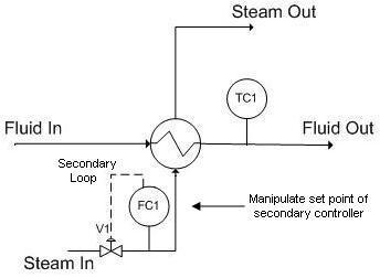
Figure 6: Automatic mode for secondary controller (manual mode for primary controller)
Now the temperature controller is set to automatic mode and the flow controller is set to manual mode. In this system the temperature controller outputs a set point to the flow controller just like it would in regular cascade mode. The temperature controller is then tuned by adjusting the output to the valve. This is shown in Figure 7 below.
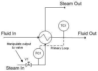
Figure 7: Manual mode for secondary controller (automatic mode for primary controller)
Developing the Structure of a Cascade Algorithm
Below is a step-by-step method through which the basic structure of a Cascade Algorithm can be developed. The examples in each step refer to Figure 3.
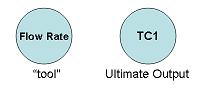
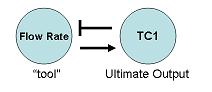
1 – Determine the goal of your algorithm. That is, which ultimate output you would like to ultimately end up changing. Also determine what “tool” (or aspect of the system) will most directly and physically allow you to accomplish this desired change.
This “tool” can be any physical property of the system: temperature, pressure, surface area, flow regime, flow rate, etc. of any part of any physical component of the system. The “tool” doesn’t need to be something read by a sensor, though it can be (as it is in this example, the temperature of the heated fluid leaving the heat exchanger is read by sensor TC1).
For instance, the end goal of the process of Figure 3 is to regulate the temperature of the fluid leaving a heat exchanger. In this case, the only way to physically accomplish this is to change the flow rate of the steam through the heat exchanger (this flow rate just so happens to be read by the sensor FC1).
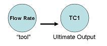
2 – Determine how the “tool” physically affects the ultimate output.
For instance, an increased flow rate of steam (read by FC1) will physically increase the temperature of the fluid leaving the heat exchanger, TC1.
3 – Determine how the ultimate output needs to affect the “tool” to achieve the desired ultimate output change.
For instance, we presume that we would like to, in general, resist any change in TC1 (i.e. we don’t want an increase in TC1 to further increase the value of TC1, that would be bad!). For this reason, we want an increase in TC1 to decrease FC1, which will then decrease TC1 (negative feedback).
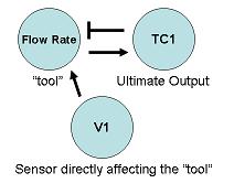
4 – Determine which valve or sensor’s output will most directly affect the “tool”. Also, determine how the sensor and “tool” are related.
For instance, the setting of valve V1 will most directly affect the flow rate of steam entering the heat exchanger (it is the "closest" controllable component of the process to the "tool", the steam flow rate). An increase in V1 will increase flow rate.
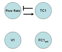
5 – Determine all valves/sensors in between the ultimate output and valve/sensor that will directly affect the “tool”.
For instance, between the ultimate output (TC1) and the valve (V1) that will directly affect the “tool”, there is only the FC1 sensor.
6 – Make an incidence graph. Make sure that you use the set points of the valves/sensors that directly affect the “tool”, because you cannot control what these sensors read (you can only control their set points). Confirm that the relationship between the “tool” and the ultimate output is consistent with the incidence graph!
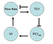
7 – Use this incidence graph to construct the algorithm. The incidence graph is particularly helpful in determining what “sign” changes in one component should result in a the “sign” in another component. If we use incidence diagrams, and the equations for the cascade controller, we can determine a relationship between the components of the system.
For instance, if TC1 were to increase, we would want the steam flow rate to decrease, which ultimately results in a decreased temperature. An increase (a “sign” of +) in TC1 should result in a decrease in FC1set (a “sign of -). This can be seen from equation 2, where if TC1set decreases, the difference between TC1set and TC1 will be smaller. This causes FC1set to decrease relative to its previous set point. A decrease (a “sign” of -) in FC1set should result in a decrease in V1 (a “sign of -). This is shown by equation 1, where if FC1set decreases while FC1 is the same, V1 will decrease relative to its previous position. A decrease (a “sign” of -) in V1 should result in a decreased flow rate (a “sign of -). A decrease (a “sign” of -) in steam flow rate should result in a decreased TC1 (a “sign of -), completing the negative-feedback mechanism initially desired.

(1)

(2)
Failure
A cascade system is not to be confused with a fail-safe system. The sole purpose of implementing a cascade control system is to make the system more responsive, not more robust.
In a cascade system, if the master controller fails, the entire system will fail too. Just like for any other design, one should anticipate failure and build in redundancy. An example of redundancy could be having multiple controllers to be the master controller and then using selectors to choose which reading to use.
Alternatively, if the cascade system fails and has no built-in redundancy, there are a couple of ways to keep the cascade system running while the controller is being repaired. For example, the controller can be operated manually by an employee, or an average of previous readings can be used to temporarily send a constant signal to the system.
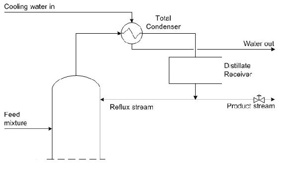
The diagram below shows the top portion of a distillation column used to separate the components of the inlet liquid mixture. Reflux is used for the column to improve the separation efficiency, as the desired product stream must have a mass fraction of component C that is greater than 0.8. At the top of the distillation column the temperature is 200oC. Components A, B, and C, which are gases at that temperature, accumulate and flow out of the top of the distillation column through the total condenser. The total condenser cools the gas stream to 150oC, causing A, B, and C to liquefy. The liquid mixture is collected in a distillate receiver. Finally, the liquid stream exits the receiver and is either collected as product or sent back to the column. A control valve is in place on the product stream to ensure that the necessary purity is attained.
On the diagram, draw the necessary controllers and valves required to implement a cascade control for the exiting stream. Also, describe the cascade control that you have implemented.
Note that this is only one possible solution to the example question. Alternatives to this solution would be to only use a composition controller with a flow controller or a temperature controller but the below solution was chosen to give an example of a multiple cascade control.
Solution
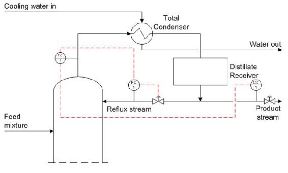
The system can most effectively be controlled with a cascade scheme. A composition controller can be installed to control the composition of the product stream. However, the composition controllers are typically slow to react since it takes time to analyze the samples to obtain compositions. In order to correct for the time lag of the composition controller, a temperature controller, located at the top of the distillation column, measures the temperature of the product stream giving a rough idea of the product composition. Additionally, a flow controller is needed on the reflux stream.
The input from the composition controller measures the composition of the product stream and sends a signal to the temperature controller at the top of the column. The temperature controller compares the set point to the measured temperature of the stream and outputs a signal to the flow controller on the recycle stream. The flow controller compares this set point to the measured flow rate and adjust the control valve on the recycle stream accordingly. This cascade control allows the system to react to disturbances quickly and to more effectively control the reflux process.
You just graduated from the University of Michigan and escaped the cold winter of Ann Arbor for a sweet full-time position in Orange County. Your company manufactures a specialty drug to cure an epidemic in the penguin population in Antarctica.
The endothermic reaction A + B --> C is run in a CSTR. A and B are toxic in even dilute concentrations. Therefore, a conversion above 99.95% has to be maintained in order to ensure the safety of the process output.
Steam from a boiler is utilized to maintain the optimum reaction temperature of 100C. A PID cascade control scheme is used to maintain this temperature.
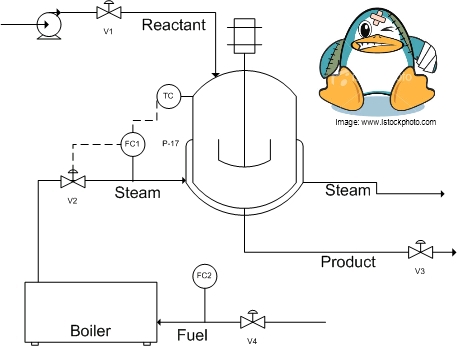
This morning, your plant manager came to you with a problem. He explained that production has been delayed because the conversion dropped below the acceptable level. He noticed that the reactor temperature was well below 100C, even though the steam valve (V2) is open completely.
As can be seen in the diagram below, a cascade control is already present in the system, but it isn't set up properly. Can you fix the problem and save the penguins?
Hint: The boiler also supplies steam to other equipment. You can increase its steam output by adding more fuel to the boiler (assume that water supply is unlimited).
Solution
Before: TC is cascaded with FC1, which controls V2. (TC-->FC1-->V2) Even when V2 is open all the way, there is not enough steam to maintain the reaction at optimum temperature.
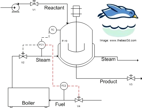
In this situation the controller surpasses the saturation limit of the actuator (V2). In other words, the controller is demanding more steam from the boiler than it can supply. A likely cause of this is a disturbance in the steam supply from the boiler because of increased steam demand from other processes. A possible solution is to increase the steam output from the boiler by adding more fuel (controlled by FC2 and V4). A side effect of this control situation would be that the I- part of a PID controller would also windup, preventing the system from responding.
An additional control loop can be added to enable the boiler output to communicate with the fuel input. In addition to controlling V2, FC1 also controls FC2, which in turn will control V4. This additional controller is shown in the figure below.
Congratulations, you just saved the penguins!
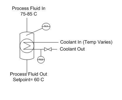
You have a holding tank for a warm process fluid that is cooled by a water-filled jacket. The process stream enters at 75-85 C and should be cooled to 60 C. The temperature of the cooling water also varies, since it comes from another process, but its average temperature is about 29 C. You have thermocouples inside the holding tank and on the cooling water jacket exit stream. Unfortunately, the tank is not well mixed, so the thermocouple reading inside the tank lags behind the actual temperature of the outlet stream. When the cooling jacket is first turned on, the tank contents are initially at 70 C. Examine the dynamics of a feedback control stream versus a cascade control scheme for this system.
Solution
One setup for this system is given in the following Excel file: Media:Cascade.xls
Under the feedback control scheme, the flow rate of coolant is adjusted based on the temperature inside the holding tank. The system overshoots setpoints more significantly, because of the lag time before disturbances are recognized.
In cascade control, the temperature sensor in the process fluid outputs a setpoint for the jacket outlet (based on a knowledge of the process fluid setpoint and the average temperature of the cooling fluid). The signal from the temperature controller on the jacket outlet controls the flow rate of cooling fluid. Since the temperature in the cooling fluid has a shorter time lag, the process remains closer to its setpoint.
We have a P&ID as shown below. Write out the equations necessary to connect LC1 to FC1 to adjust v1. Which equation is the slave and which one is the master? 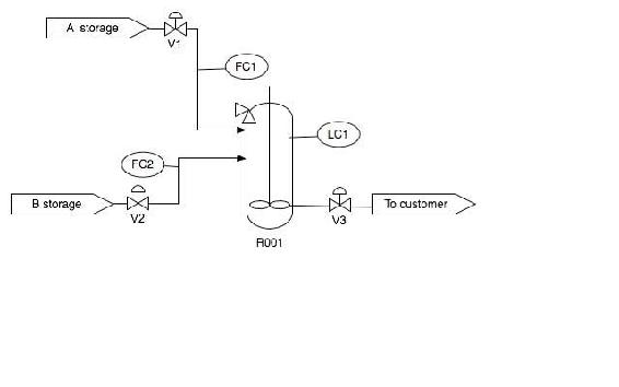
Solution
The first equation is the slave and the second equation is the master. We have to use the FC1set to determine what V1 should be set as. And these are both based on the level in the tank.

(1)

(2)
Write the general equation that describes the behavior of the cascade control system shown below. Include changes in U1 and U2.
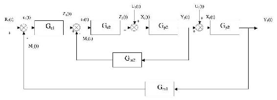
Hint: Start by writing the inner loop and outer loop equations separately.
Solution
For inner cycle:
ε1 = Z1 + GM2Y2
Z2 = Z1GC2 − Y2GC2GM2
X2 = U2 + Z2 = U2 + Z1GC2 − Y2GC2GM2
Y2 = GP2X2 = U2GP2 + Z1GP1GC2 − Y2GC2GM2GP2
For outer cycle:
Z1 = R1GC1 − Y1GM1GC1
Y1 = U1GP1 + Y2GP1
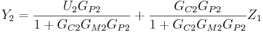
Combining Z1 from outer cycle with Y2 from inner cycle:

Combining Y2 above with Y1 from outer cycle:

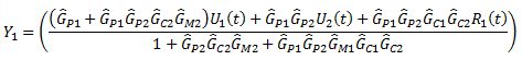
Rearranging and solving explicitly for Y1:

Practice Quiz
Answer the five questions below with the most appropriate solution. There is one correct answer for each question. Correct answers are awarded 4 points, whereas a loss of 2 points occurs for incorrect answers. Good luck!
1. Which of the following is never true in a process controlled by a cascade control scheme?
a) Changes in the secondary control variable affect the primary measured variable.
b) Disturbances in the secondary loops propagate at least four times faster than disturbances in the primary loop.
c) One control variable is used to influence the primary and secondary measured variables.
d) Major disturbances in the process are detected in the primary loop.
2. Which of the following in not an advantage of cascade control?
a) The system reacts to disturbances more quickly.
b) More efficient control of the primary variable.
c) It is a cheap control scheme to implement.
d) The effects of dead time and phase lag time are reduced in the system.
3. True or False: During start-up of a cascade control system, after the primary and secondary controllers are turned and placed in automatic mode, the primary controller gain should be increased to reduce system oscillations.
4. The primary loop, or outer loop, involves which of the following variables?
a) Control variable
b) Temperature variable
c) Reference variable
d) I love penguins (variable)
5. True or False: The primary loop is generally a function of the secondary loop.
Answers
Based on your selections, calculate your score on this quiz.
1. C- Cascade control schemes use multiple control variables for one manipulated variable.
2. C- Increased amounts of equipment and instrumentation may drive up the cost of the process.
3. False- The controller gain (Kc) should be reduced to reduce system oscillations
4. A- The best answer is (a) since the control variable may or may not be temperature. The reference variable is involved in the secondary loop. Penguins are really cute.
5. True- The output of the primary controller is the set point for the secondary controller. The output of the secondary controller adjusts the control variable.
Scoring
If you got…
20 points: CONGRATULATIONS! You are a cascade genius!
13-19 points: Make a list of confusing topics and bring your questions to a cascade control sage.
0-12 points: You may want to re-read this article and try again…
-10 points: Choose a new major. You may be better off in LS&A.
References
- Astrom, Karl J. and Hagglund, Torr. "Advanced PID Control" The Instrumentation, Systems and Automation Society.
- Bequette, B. Wayne Process Dynamics: Modeling, Analysis, and Simulation Prentice- Hall PTR, Upper Saddle River, NJ 07458 (c) 2006.
- Mahoney, D.P., Svrcek, W.Y., and Young, B.R. (2006) A Real-Time Approach to Process Control, 2nd Edition. John Wiley & Sons, Ltd. ISBN 0470025336
- Industrial Controller: basic theory. Retrieved from http://www.sapiensman.com/control/index.htm. Last accessed on 12/12/2008
Contributors and Attributions
- Stewards: Irene Brockman, Robert Chockley, Scott Dombrowski, Chloe Sweet