
1.13: Influence Lines for Statically Indeterminate Structures
- Page ID
- 17620

Influence Lines for Statically Indeterminate Structures
The influence lines for statically indeterminate structures are obtained by the static equilibrium method or by the kinematic method, as was the case for determinate structures. The procedures for finding influence lines for indeterminate structures by these methods are similar to those outlined in chapter nine for determinate structures. The distinguishing feature between the graphs of the influence lines for determinate and indeterminate structures is that the former contains straight lines while the later consists of curves. The analysis and constructions of the influence lines using the equilibrium and kinematic methods are discussed in this chapter.
13.2 Static Equilibrium Method
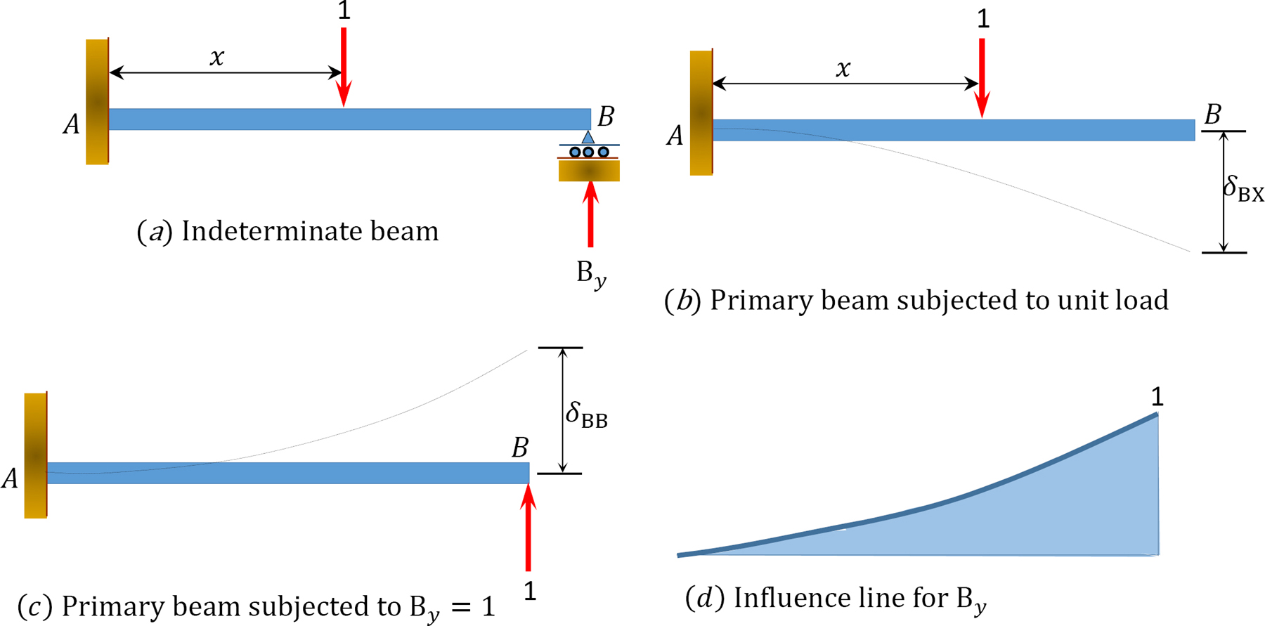
To construct the influence line for the reaction at the prop of the cantilever beam shown in Figure 13.1, first determine the degree of indeterminacy of the structure. For the propped cantilever, the degree of indeterminacy is one, as the beam has four reactions (three at the fixed end and one at the prop). Thus, the propped cantilever has one reaction more than the three equations of equilibrium. Considering the reaction at the prop as the redundant and removing it from the system provides the primary structure. The next step is to apply a unit load at various distances x from the fixed support and at the position where the redundant was removed. Then, compute the deflections at these points on the beam using any method. The redundant By at the prop can be determined using the following compatibility equation:
δBX + δBBBy = 0
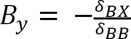
From which

where
δBX = deflection at B due to the unit load at any arbitrary point on the primary structure at a distance x from the fixed support.
δBB = deflection at B due to the unit value of the redundant (i.e., By = 1).
Example 13.1
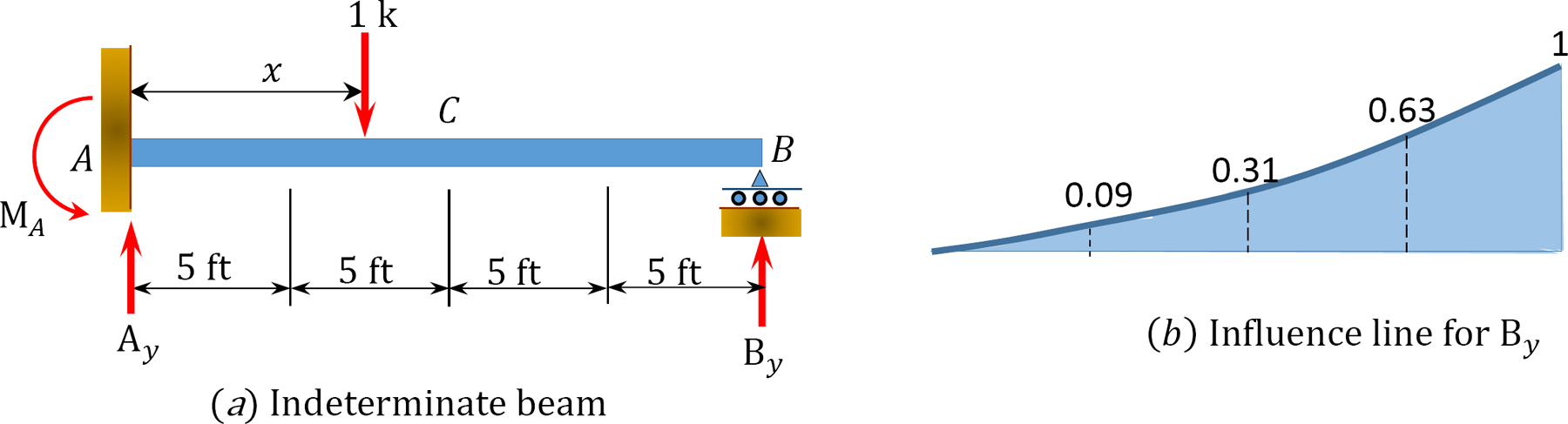
Draw the influence lines for the reactions at supports A and B and the moment and shear force at point C of the propped cantilever beam shown in Figure 13.2a.

Solution
The degree of indeterminacy of the beam is one. By selecting the reaction at the prop as the redundant, the value of this redundant can be determined by solving the following compatibility equation when the unit load is located at any point x along the beam:
δBX + δBBBy = 0
Therefore,
Using the deflection formulas provided in appendix A of this book, the deflections at the prop due to a unit load acting at a quarter span interval along the beam can be determined as follows:
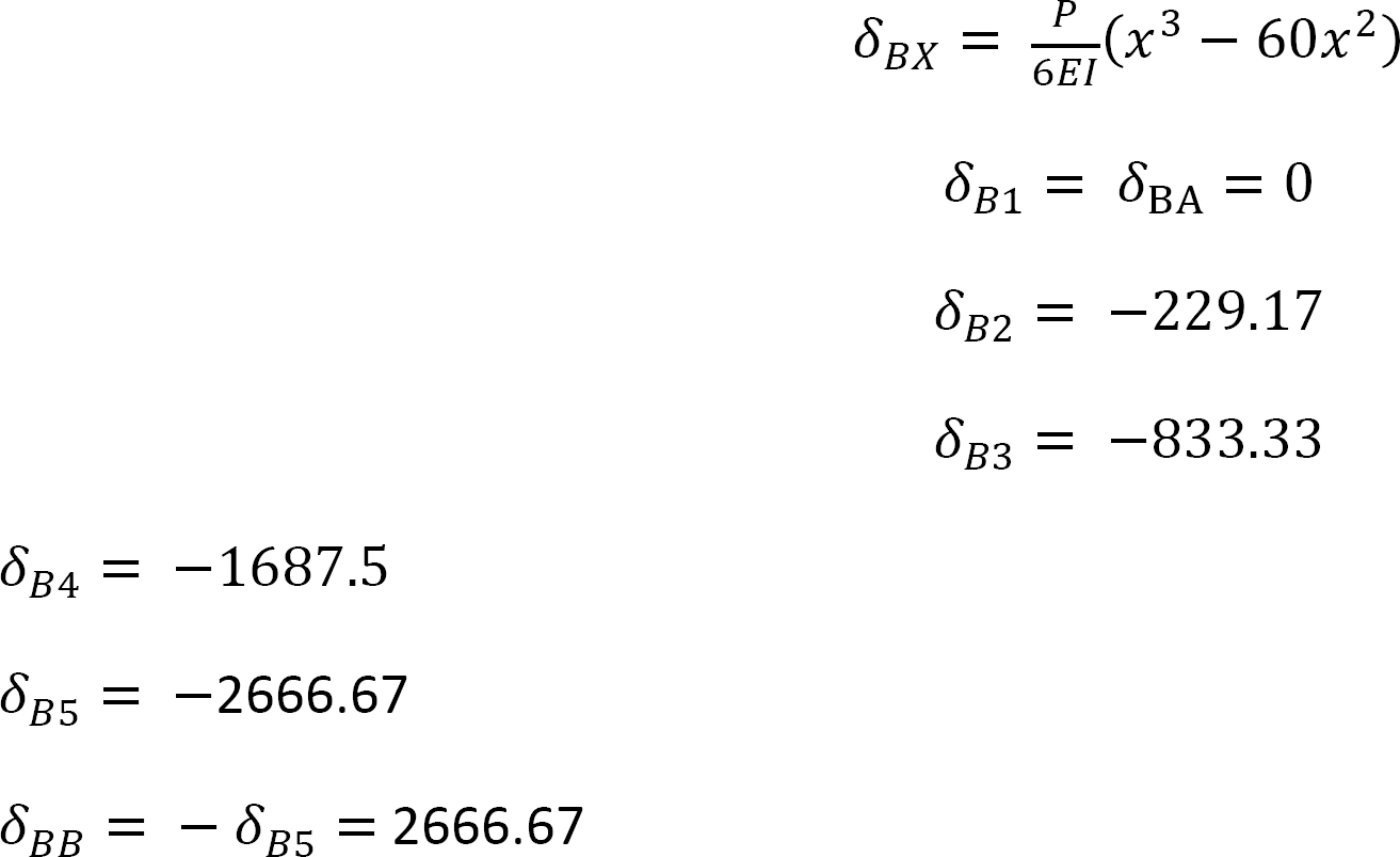
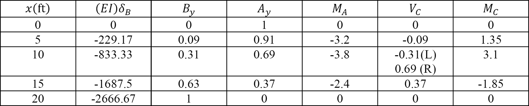
The ordinates of the influence lines for the desired functions are tabulated in Table 13.1
Table 13.1.
Example 13.2
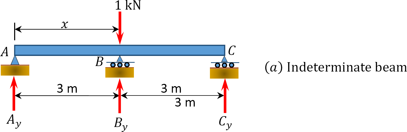
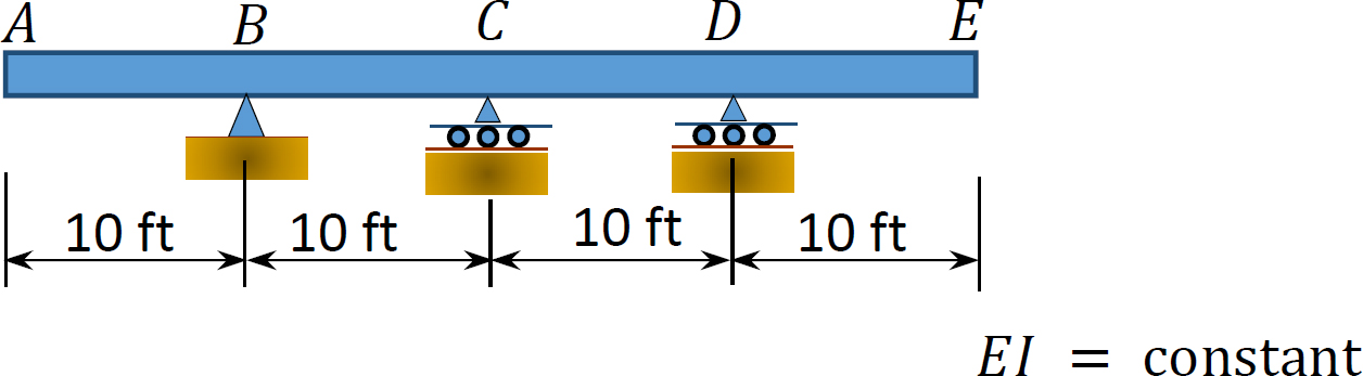
Draw the influence lines for the reactions at the supports A, B, and C of the indeterminate beam shown in Figure 13.3.

Solution
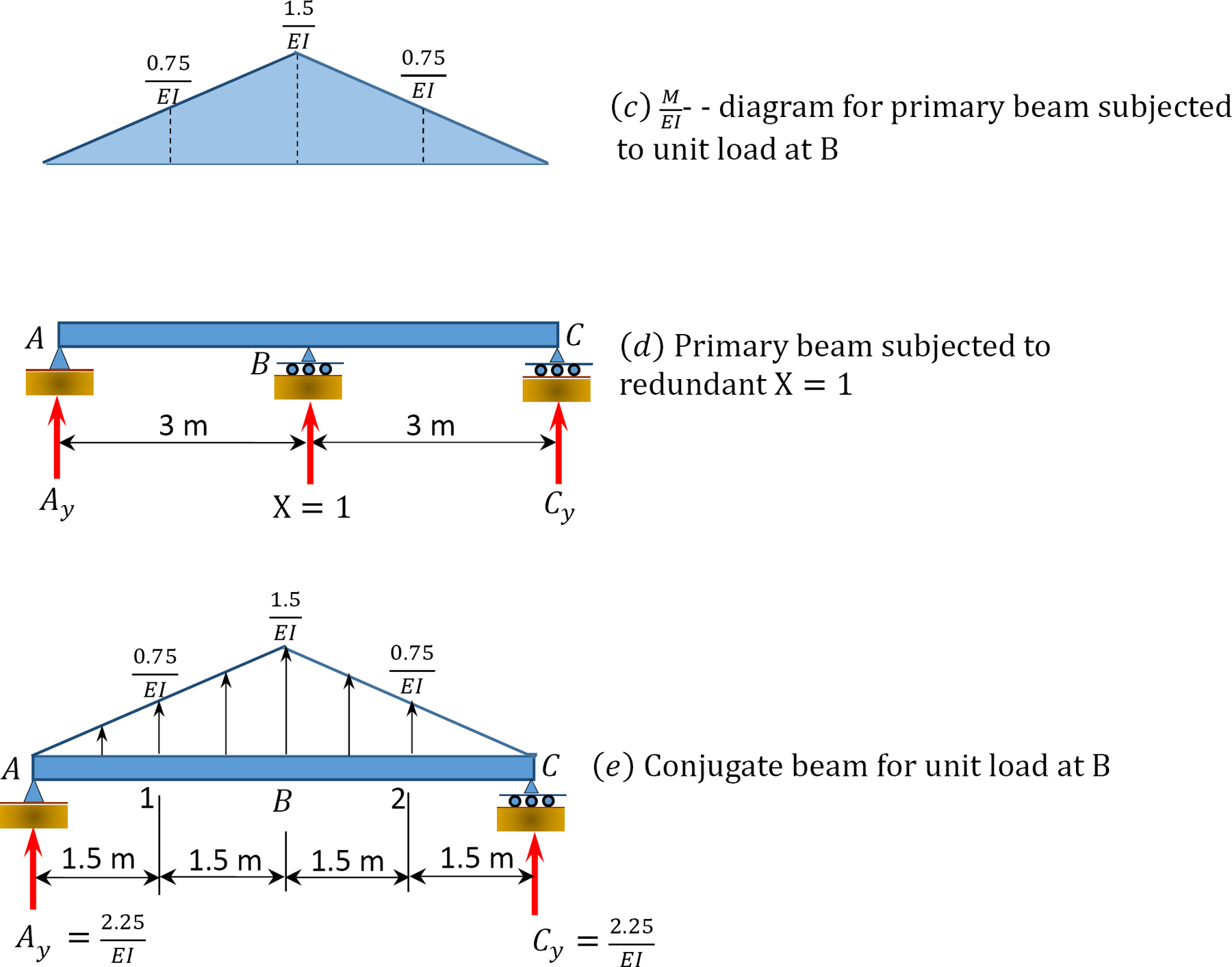
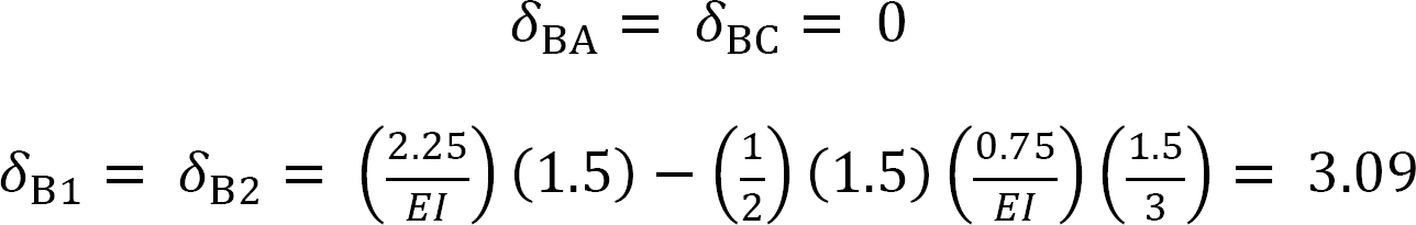
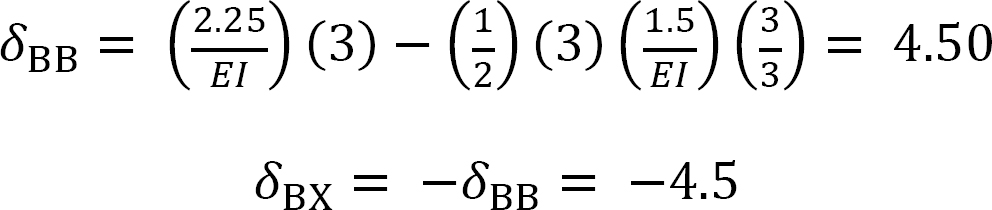
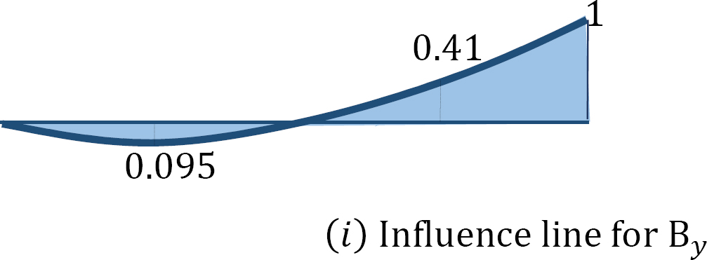
When the unit load is at different points along the beam, the ordinate of the influence line for the redundant at By can be computed using the compatibility equation:
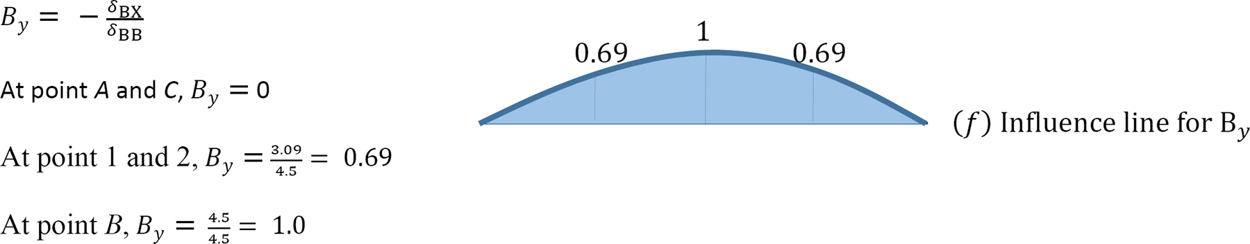
Now that By is known, the values of the ordinate of the influence lines for other reactions can be obtained using statics. For instance, to determine the ordinate of the influence line at point 1, place the unit load at point 1 and the value of the redundant when the unit load is at point 1 and solve as follows:
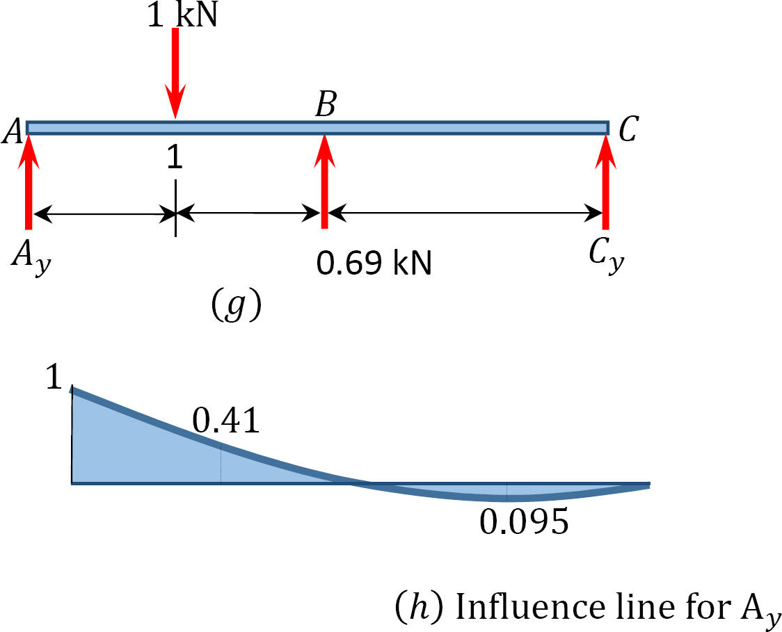
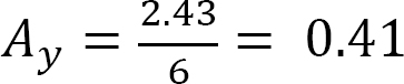
Ordinates of influence line for Ay.
+↶ ∑ MC = 0
When the unit load is at point 1,
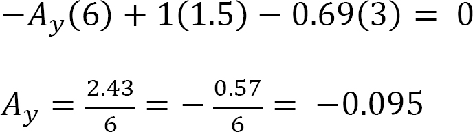
–Ay(6) + 1(4.5) – 0.69(3) = 0
When the unit load is at point 2,
When the unit load is at point A, Ay = 1
When the unit load is at point B and C, Ay = 0
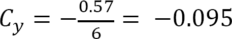
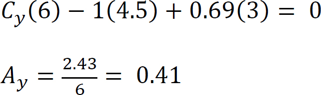
Ordinates of Influence line for Cy.
+↶ ∑ MA = 0
When the unit load is at point 1,
Cy(6) – 1(1.5) + 0.69(3) = 0
When the unit load is at point 2,
When the unit load is at point C, Cy = 1
When the unit load is at point A and B, Cy = 0
13.3 Influence Lines for Statically Indeterminate Beams by Kinematic Method
In 1886, Heinrich Muller-Breslau, a German Professor, developed a procedure for the establishment of the shape of the influence lines for functions such as reactions, shears, moments, and axial forces in members without any computational effort. The influence lines obtained by this method are also referred to as qualitative influence lines, as there is no calculation involved. The Muller-Breslau method is based on the principle of virtual work. The procedure for this method, which is commonly referred to as Muller-Breslau’s principle, is stated as follows:
The influence line for any function such as a reaction, shear, or moment of a structure can be represented by the deflected shape of a release structure obtained by removing from the given structure the restraint that corresponds to the particular function being considered, and then introducing a unit displacement or rotation in the direction and the location of the function being considered.
When there is a need to obtain the ordinates for the influence lines while using the kinematic method, this procedure must be complemented by other analytical techniques, such as the method of singularity function, the Hardy Cross method of moment distribution, the energy methods, and the conjugate beam principle. In such instances, the procedure is as follows:
Procedure for Analysis of Influence Lines by the Kinematic Method
•Obtain the released structure by removing the restraint that corresponds to the function whose influence line is desired.
•Apply a unit displacement or rotation to the released structure in the direction and at the location of the function whose influence line is desired.
•Draw the deflected shape of the released structure. This corresponds to the influence line of the function being considered.
•Place a unit load at the location and in the direction of the function being considered, and find the value of the ordinate of the influence line using statics.
•Using geometry, determine the value of other ordinates of influence using geometry.
Example 13.3
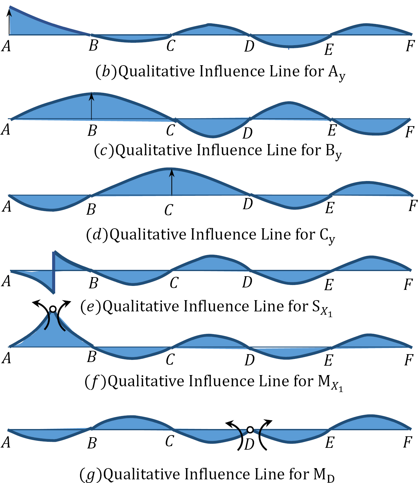
Using the Muller-Breslau’s principle, draw the qualitative influence lines for the vertical reactions at supports A, B, and C, the shear and bending moment at section X1, and the bending moment at support D of the five-span beam shown in Figure 13.4a.
Solution
Qualitative influence line for the vertical reactions at support A, B, and C.
To draw the qualitative influence line for Ay, first obtain the release structure by removing the support at A. Applying a unit displacement at point A in the release structure, in the positive direction of Ay, will result in the deflected shape shown in Figure 13.4b. The resulting deflected shape represents the shape of the influence line of Ay. To obtain the shape of the influence lines for By and Cy, similar procedures are followed and will yield the deflected shapes shown in Figure13.4c and Figure13.4d.
Qualitative influence lines for the shear at section X1.
The qualitative influence line for the shear at section X1 is drawn by first breaking the beam at the section and then applying two vertical forces in a manner that will cause a positive shear on the left and the right portion of the break. The resulting deflected shape is shown in Figure 13.4e.
Qualitative influence lines for the bending moment at section X1.
The influence line of the moment at section X1 is found by first inserting an imaginary hinge at the section X1 and then applying a pair of positive bending moments adjacent to both sides of the hinge. The resulting deflected shape shown in Figure 13.4f represents the shape of the qualitative influence line for the bending moment at the section.
Qualitative influence lines for the bending moment at support D.
The influence line for the moment at the support D is obtained by first releasing the restrain at the support, inserting a pin at point D of the release structure, and then applying a pair of moments adjacent to both sides of the hinge in the positive direction of MD. The resulting deflected shape shown in Figure 13.4g represents the shape of the qualitative influence line for the bending moment at the section.

Chapter Summary
Influence lines for indeterminate structures: The procedure for the construction of influence lines for indeterminate structures by the equilibrium method and the Muller-Breslau principle were discussed, and a few example problems were solved in this chapter. Unlike the influence lines for determinate structures, which are straight lines, the influence line for indeterminate structures are curvilinear.
Practice Problems
13.1 Using the equilibrium method, draw the influence lines for the vertical reactions at ACD of the beam shown in Figure P13.1. Also, draw the influence line for the shear force and bending moment at a section at B of the beam.

13.2 Using the equilibrium method, draw the influence lines for the vertical reactions at the supports of the indeterminate beam with overhanging ends, as shown in Figure P13.2.
13.3 Using the equilibrium method, draw the influence lines for the vertical reactions at supports A and C of the propped cantilever beam shown in Figure P13.3.

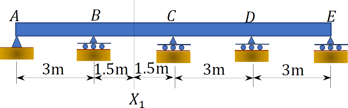
13.4 Using Muller-Breslau’s principle, draw the qualitative influence lines for the vertical reactions at supports A, B, and C, positive shear and moment at section X1.
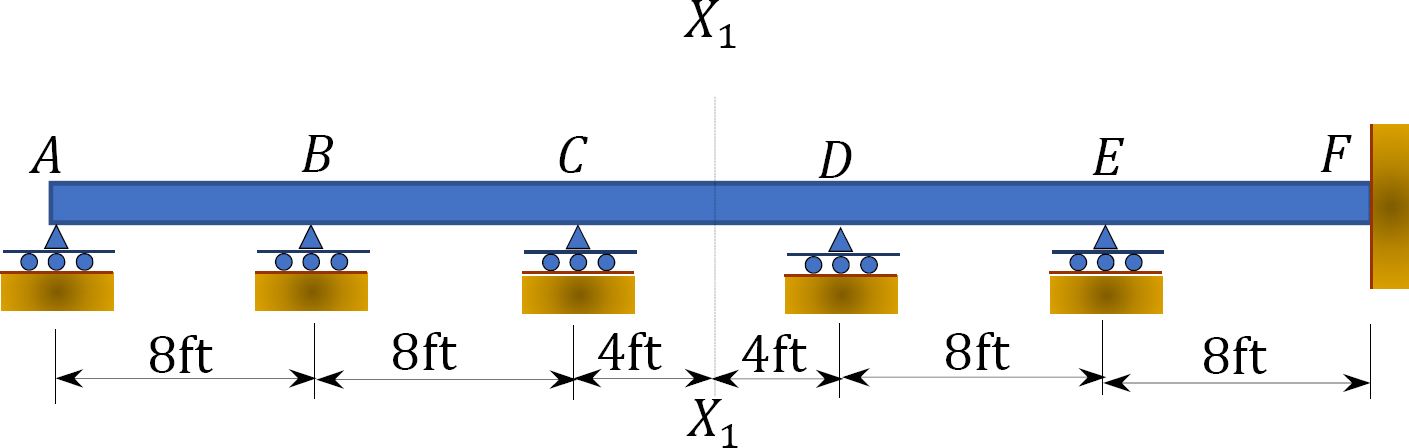
13.5 Using Muller-Breslau’s principle, draw the qualitative influence lines for the vertical reactions at supports E and F, the negative moment at C, negative shear and moment at section X1.
13.6 Using Muller-Breslau’s principle, draw the qualitative influence lines for the maximum vertical reactions at supports A and B, maximum negative shear and moment at section X1.
