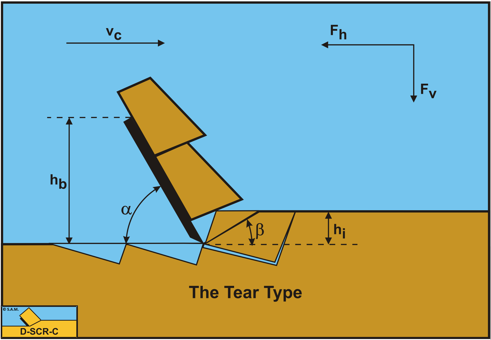
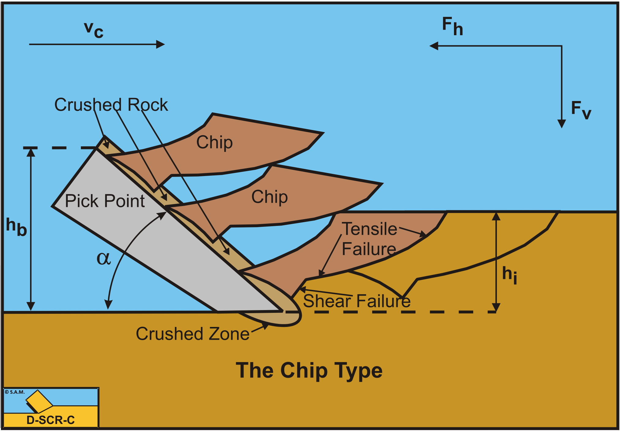
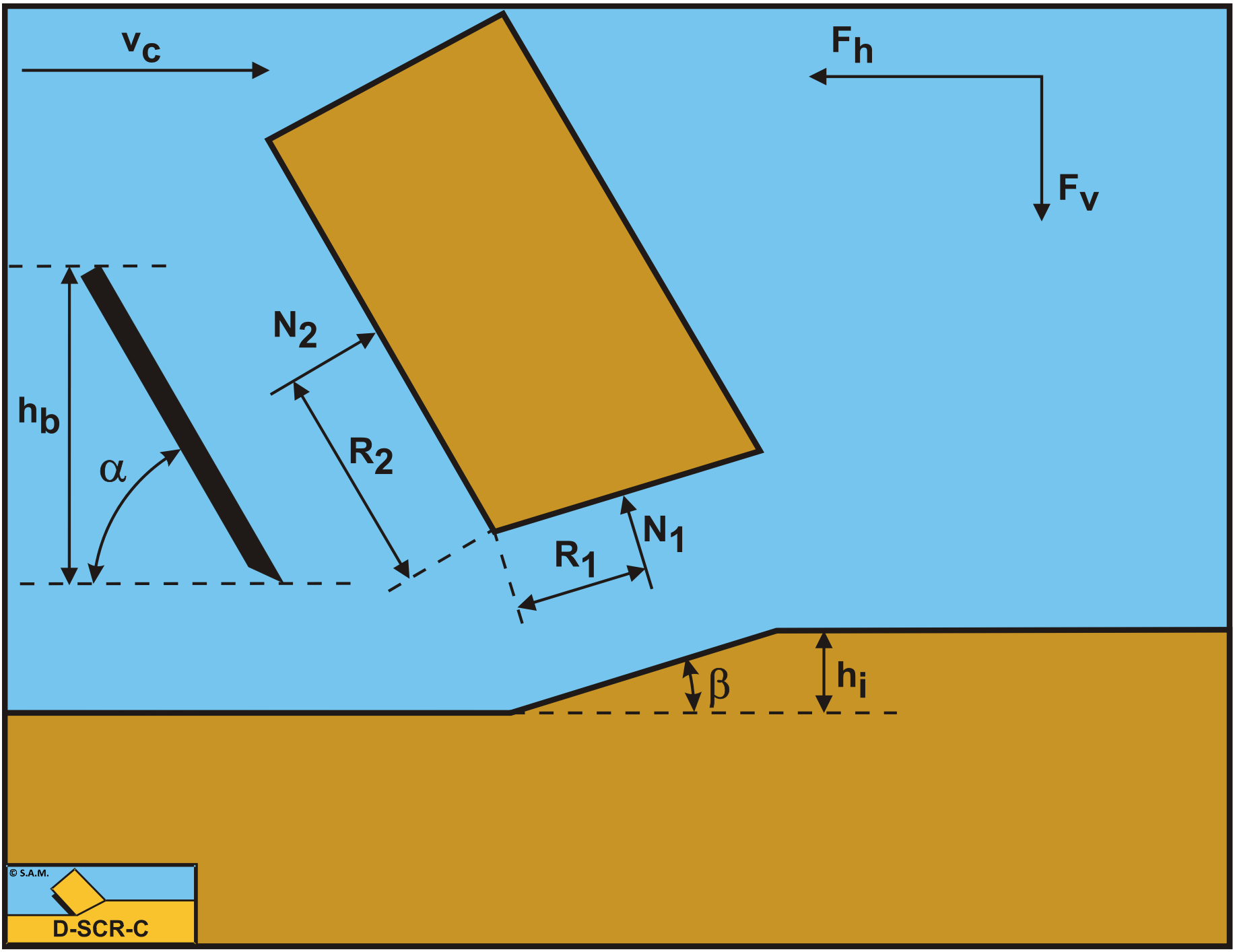
8.6: The Shear Type, Tear Type and the Chip Type
- Page ID
- 29469

Until now only the total normal force on the shear plane N1 has been taken into consideration, but of course this normal force is the result of integration of the normal stresses σN1 on the shear plane. One could consider that cutting is partly bending the material and it is known that with bending a bar, at the inside (the smallest bending radius) compressive stresses will be developed, while at the outside (the biggest bending radius), tensile stresses are developed. So if the normal force N1 equals zero, this must mean that near the edge of the blade tensile stresses (negative) stresses develop, while at the outside compressive (positive) stresses develop. So even when the normal force would be slightly positive, still, tensile stresses develop in front of the edge of the blade. The normal force on the blade however is always positive, meaning that the Curling Type of cutting process will never occur in rock under atmospheric conditions. The previous derivations of the cutting forces are based on the Flow Type, but in reality rock will fail brittle with either the Shear Type or the Tear Type or a combination the Chip Type. For the Shear Type the equations (8-109) and (8-110) can still be used, considering these equations give peak forces. The average forces and thus the average cutting power Pc and the specific energy Esp may be 30%-60% of the peak values. The occurrence of the Tear Type depends on the tensile stress. If somewhere in the rock the tensile stress σmin is smaller than the tensile strength σT, a tensile fracture may occur. One should note here that compressive stresses are positive and tensile stresses are negative. So tensile fracture/rupture will occur if the absolute value of the tensile stress σmin is larger than the tensile strength σT.
If rock is considered, the following condition can be derived with respect to tensile rupture:
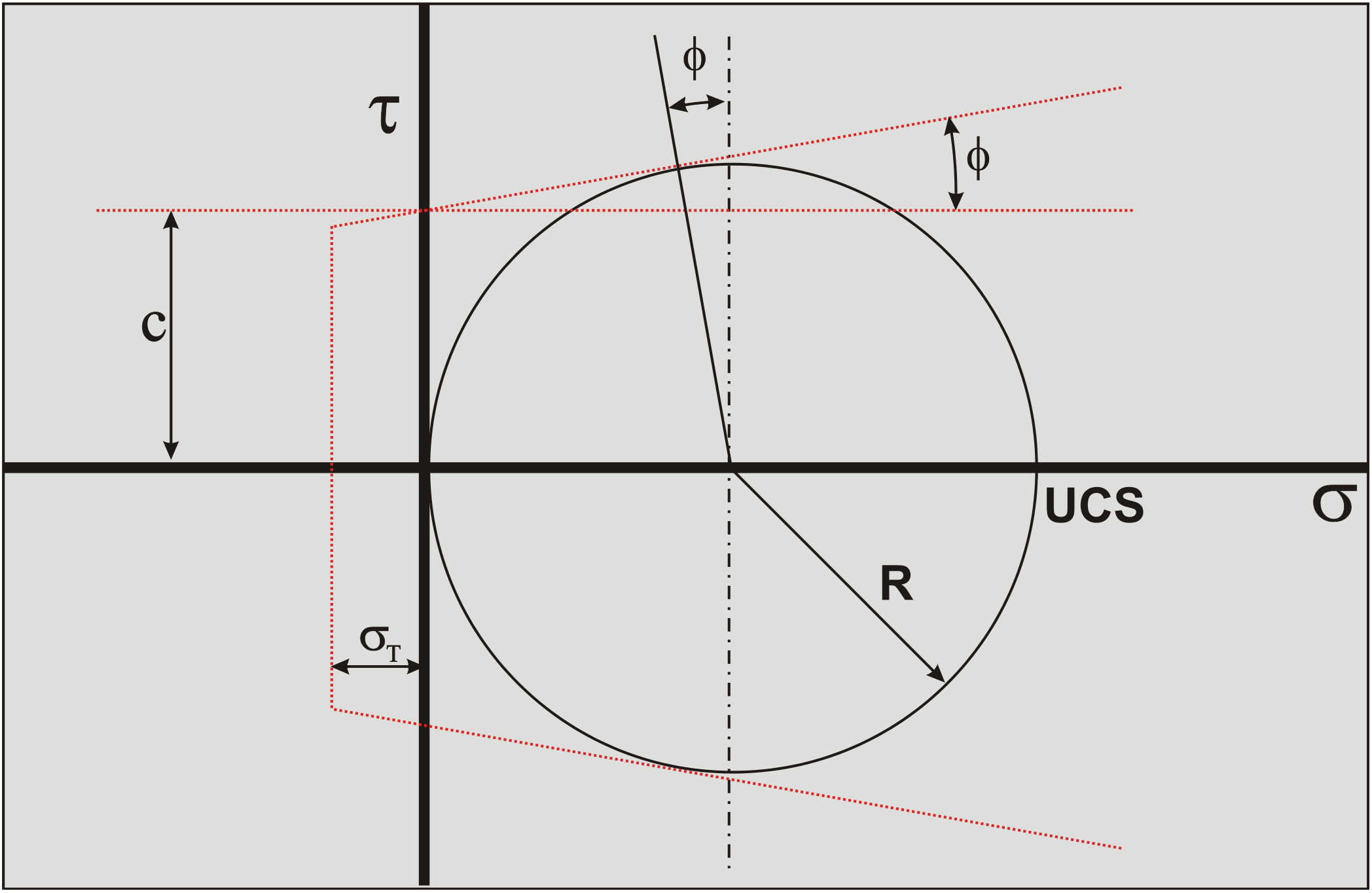
The cohesion c can be determined from the UCS value and the angle of internal friction according to, as is shown in Figure 8-36:
\[\ \mathrm{c=\frac{U C S}{2} \cdot\left(\frac{1-\sin (\varphi)}{\cos (\varphi)}\right)}\tag{8-117}\]
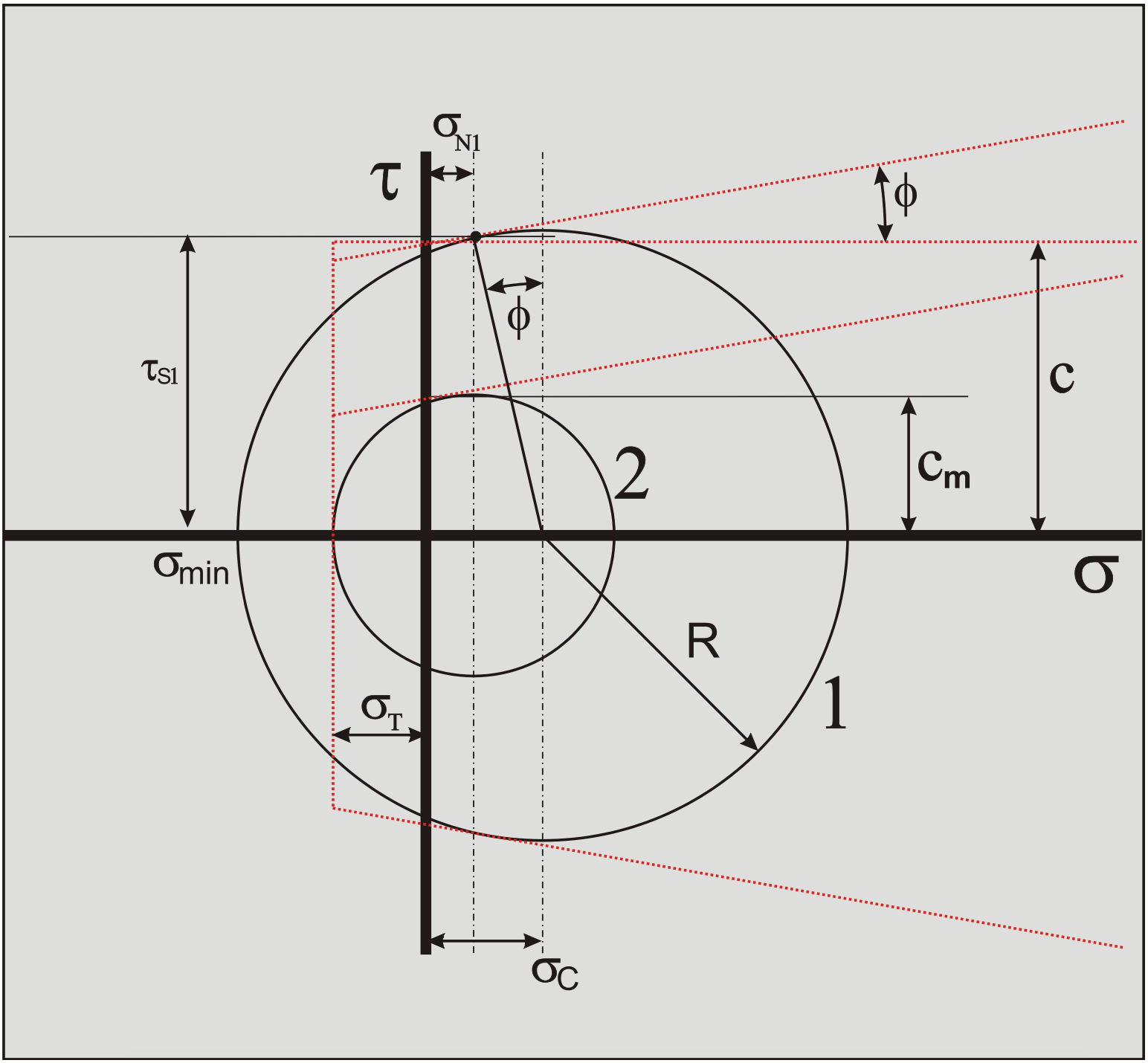
According to the Mohr-Coulomb failure criterion, the following is valid for the shear stress on the shear plane, as is shown in Figure 8-37.
\[\ \tau_{\mathrm{S} 1}=\mathrm{c}+\sigma_{\mathrm{N} 1} \cdot \tan (\varphi)\tag{8-118}\]
The average stress condition on the shear plane is now σN1, \(\ \tau\)S1 as is shown in Figure 8-37. A Mohr circle (Mohr circle 1) can be drawn through this point, resulting in a minimum stress σmin which is negative, so tensile. If this minimum normal stress is smaller than the tensile strength σT tensile fracture will occur, as is the case in the figure. Now Mohr circle 1 can never exist, but a smaller circle (Mohr circle 2) can, just touching the tensile strength σT. The question is now, how to get from Mohr circle 1 to Mohr circle 2. To find Mohr circle 2 the following steps have to be taken.
The radius R of the Mohr circle 1 can be found from the shear stress \(\ \tau\)S1 by:
\[\ \mathrm{R}=\frac{\tau_{\mathrm{S} 1}}{\cos (\varphi)}\tag{8-119}\]
The center of the Mohr circle 1, σC, now follows from:
\[\ \begin{array}{left} \sigma_{\mathrm{C}} &=\sigma_{\mathrm{N} 1}+\mathrm{R} \cdot \sin (\varphi)=\sigma_{\mathrm{N} 1}+\tau_{\mathrm{S} 1} \cdot \tan (\varphi) \\ &=\sigma_{\mathrm{N} 1}+\mathrm{c} \cdot \tan (\varphi)+\sigma_{\mathrm{N} 1} \cdot \tan ^{2}(\varphi) \end{array}\tag{8-120}\]
The minimum principal stress σmin equals the normal stress in the center of the Mohr circle σC minus the radius of the Mohr circle R:
\[\ \begin{array}{left} \sigma_{\min } &=\sigma_{\mathrm{C}}-\mathrm{R} \\ &=\sigma_{\mathrm{N} 1}+\mathrm{c} \cdot \tan (\varphi)+\sigma_{\mathrm{N} 1} \cdot \tan ^{2}(\varphi)-\frac{\mathrm{c}}{\cos (\varphi)}-\frac{\sigma_{\mathrm{N} 1} \cdot \tan (\varphi)}{\cos (\varphi)} \end{array}\tag{8-121}\]
Rearranging this gives:
\[\ \sigma_{\min }=\sigma_{\mathrm{N} 1} \cdot\left(1+\tan ^{2}(\varphi)-\frac{\tan (\varphi)}{\cos (\varphi)}\right)+\mathrm{c} \cdot\left(\tan (\varphi)-\frac{1}{\cos (\varphi)}\right)\tag{8-122}\]
Substituting equation (8-111) for the normal stress on the shear plane gives:
\[\ \sigma_{\min }= \frac{-\mathrm{c} \cdot \cos (\alpha+\beta+\delta) \cdot \cos (\varphi)}{\sin (\alpha+\beta+\delta+\varphi)} \cdot\left(1+\tan ^{2}(\varphi)-\frac{\tan (\varphi)}{\cos (\varphi)}\right) +\mathrm{c} \cdot\left(\tan (\varphi)-\frac{1}{\cos (\varphi)}\right)>\sigma_{\mathrm{T}} \tag{8-123}\]
Now shear failure will occur if the minimum principal stress σmin is larger than the tensile strength σT, thus:
\[\ \sigma_{\min }>\sigma_{\mathrm{T}}\tag{8-124}\]
If equation (8-124) is true, shear failure will occur. Keep in mind however, that the tensile strength σT is a negative number. Of course if the minimum normal stress σmin or in the graph, Figure 8-38, σT / c is positive, tensile failure can never occur. Equation (8-124) can be transformed to:
\[\ \frac{\sigma_{\mathrm{T}}}{\mathrm{c}}<-\frac{\cos (\alpha+\beta+\delta)}{\sin (\alpha+\beta+\delta+\varphi)} \cdot(\cos (\varphi)-\tan (\varphi)+\tan (\varphi) \cdot \sin (\varphi))
+\tan (\varphi)-\frac{1}{\cos (\varphi)}\tag{8-125}\]
Substituting equation (8-108) for the shear angle β gives:
\[\ \frac{\sigma_{\mathrm{T}}}{\mathrm{c}}<\frac{\sin \left(\frac{\alpha+\delta-\varphi}{2}\right)}{\cos \left(\frac{\alpha+\delta+\varphi}{2}\right)} \cdot(\cos (\varphi)-\tan (\varphi)+\tan (\varphi) \cdot \sin (\varphi))
\quad+\tan (\varphi)-\frac{1}{\cos (\varphi)}\tag{8-126}\]
This can be transformed to:
\[\ \mathrm{\frac{\sigma_{T}}{c}<\left(\frac{\sin \left(\frac{\alpha+\delta-\varphi}{2}\right)}{\cos \left(\frac{\alpha+\delta+\varphi}{2}\right)}-1\right) \cdot\left(\frac{1-\sin (\varphi)}{\cos (\varphi)}\right)}\tag{8-127}\]
A mobilized cohesive shear strength cm can be defined, based on the tensile strength σT, by using the equal sign in equation (8-127). With this mobilized cohesive shear strength Mohr circle 2 can be constructed.
\[\ \mathrm{c}_{\mathrm{m}}=\frac{\sigma_{\mathrm{T}}}{\left(\frac{\sin \left(\frac{\alpha+\delta-\varphi}{2}\right)}{\cos \left(\frac{\alpha+\delta+\varphi}{2}\right)}-1\right) \cdot\left(\frac{1-\sin (\varphi)}{\cos (\varphi)}\right)}\tag{8-128}\]
Substituting equation (8-128) in the equations (8-109) and (8-110) gives for the cutting forces:
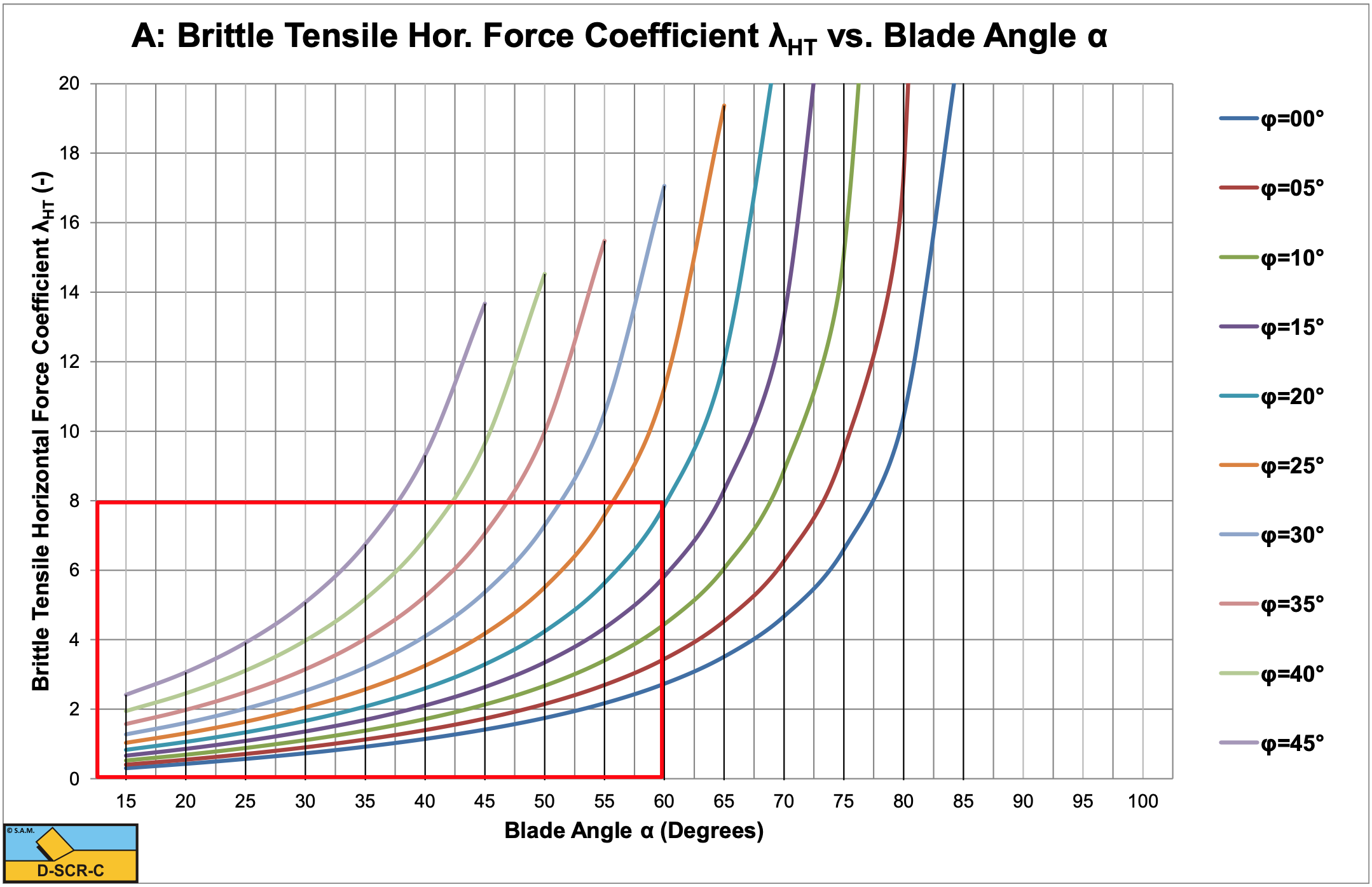
\[\ \mathrm{F_{h}=\frac{2 \cdot c_{m} \cdot h_{i} \cdot w \cdot \cos (\varphi) \cdot \sin (\alpha+\delta)}{1+\cos (\alpha+\delta+\varphi)}=\lambda_{H T} \cdot \sigma_{T} \cdot h_{i} \cdot w}\tag{8-129}\]
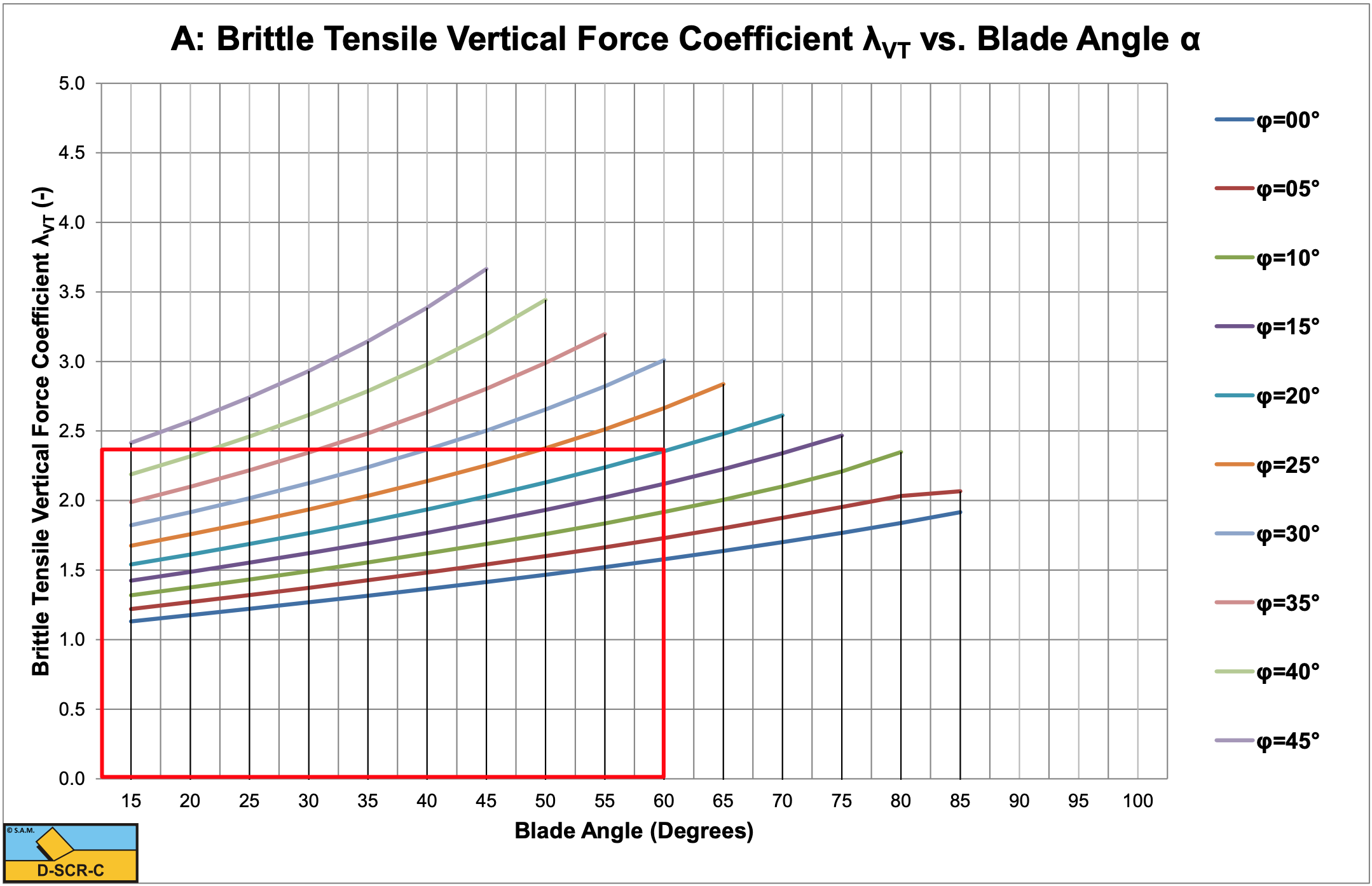
\[\ \mathrm{F}_{v}=\frac{\mathrm{2} \cdot \mathrm{c}_{\mathrm{m}} \cdot \mathrm{h}_{\mathrm{i}} \cdot \mathrm{w} \cdot \cos (\varphi) \cdot \cos (\boldsymbol{\alpha}+\delta)}{\mathrm{1}+\mathrm{c o s}(\boldsymbol{\alpha}+\delta+\varphi)}=\lambda_{\mathrm{V T}} \cdot \sigma_{\mathrm{T}} \cdot \mathrm{h}_{\mathrm{i}} \cdot \mathrm{w}\tag{8-130}\]
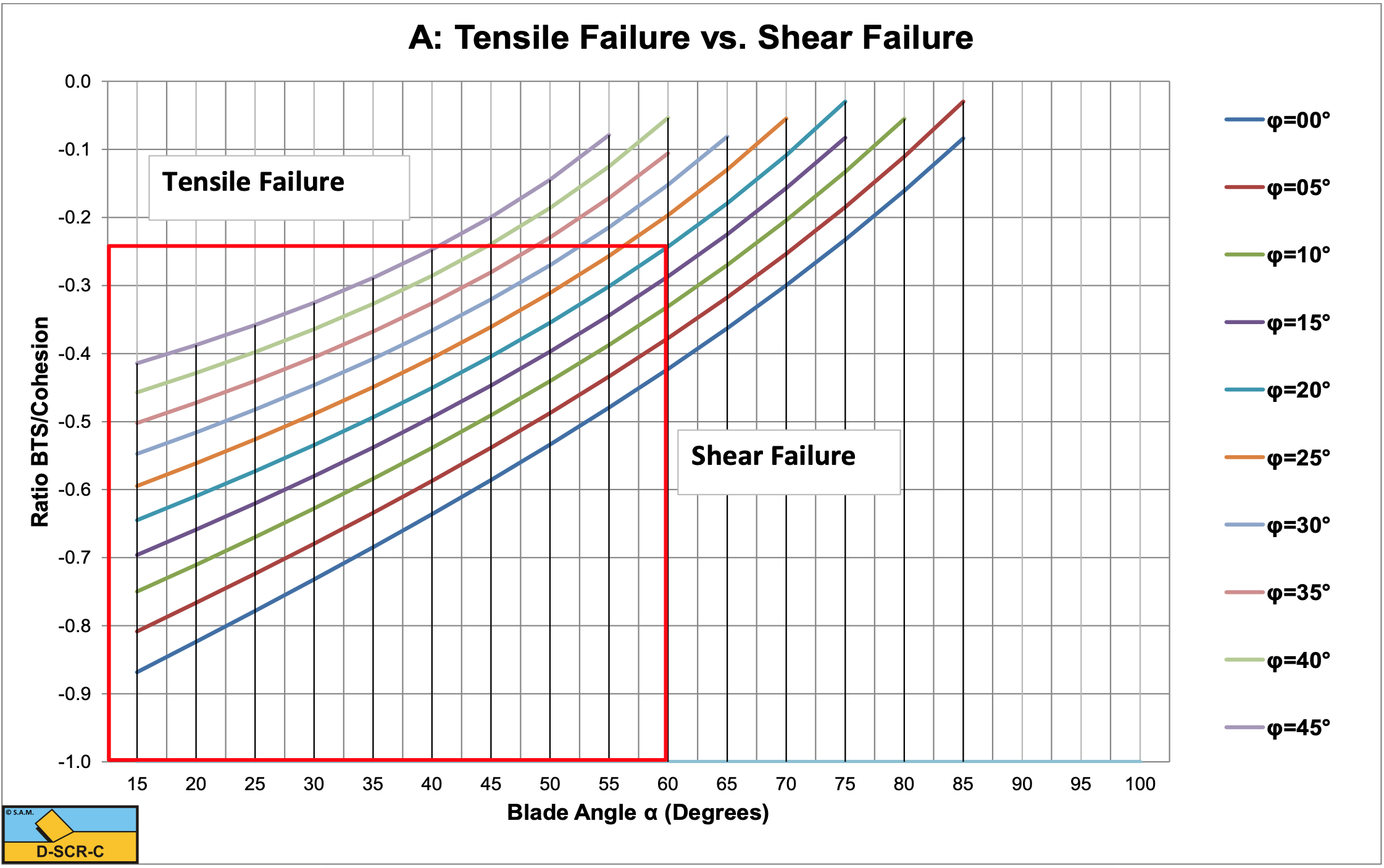
Figure 8-38 shows the pseudo cohesive shear strength coefficient σT / c from equation (8-127). Below the lines the cutting process is ductile (the Flow Type) or brittle (the Shear Type), while above the lines it is brittle (the Tear Type). It is clear from this figure that an increasing blade angle α and an increasing internal friction angle φ suppresses the occurrence of the Tear Type. The coefficients λHT and λVT are shown in Figure 8-42 and Figure 8-43 for a range of blade angles α and internal friction angles φ.
Equation (8-129) gives for the specific energy Esp:
\[\ \mathrm{E}_{\mathrm{s p}}=\lambda_{\mathrm{H T}} \cdot \sigma_{\mathrm{T}}\tag{8-131}\]
To determine the cutting forces in rock under atmospheric conditions the following steps have to be taken:
-
Determine whether the cutting process is based on the Flow Type or the Tear Type, using Figure 8-38.
-
If the cutting process is based on the Flow Type, use Figure 8-31 and Figure 8-32 to determine the coefficients λHF and λVF. Use equations (8-109) and (8-110) to calculate the cutting forces. Optionally a factor 0.3-0.5 may be applied in case of brittle shear failure, to account for average forces, power and specific energy.
-
If the cutting process is based on the Tear Type, use Figure 8-42 and Figure 8-43 to determine the coefficients λHT and λVT. Use equations (8-129) and (8-130) to calculate the cutting forces. A factor 0.3-0.6 should be applied to account for average forces, power and specific energy.
For completeness, Figure 8-40 shows the moments on the layer cut.
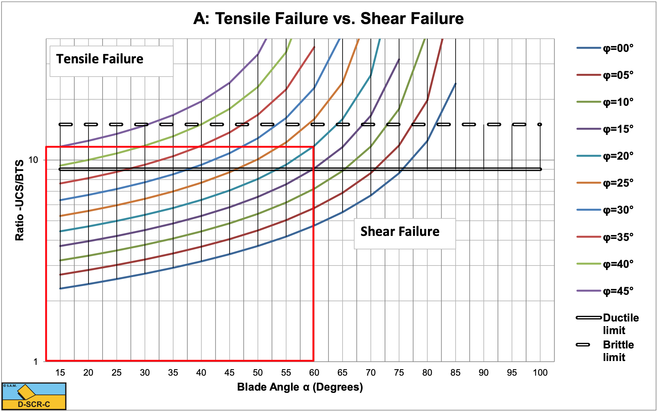
Based on equation (8-127) and (8-117) the ratio UCS/BTS can also be determined. Gehking (1987) stated that below a ratio of 9 ductile failure will occur, while above a ratio of 15 brittle failure will occur. In between these limits there is a transition between ductile and brittle failure, which is also in accordance with the findings of Fairhurst (1964). Figure 8-39 shows that the ductile limit of 9 is possible for blade angles α between 45o and 60o corresponding with internal friction angles φ of 25o and 15o. For the same blade angles, the corresponding internal friction angles φ are 35o and 25o at the brittle limit of 15. These values match the blade angles as used in dredging and mining and also match the internal friction angle of commonly dredged rock. Figure 8-39 shows that in general a higher internal friction angle φ and a bigger blade angle α suppress tensile failure.
\[\ \frac{\mathrm{UCS}}{\mathrm{BTS}}=\frac{2}{\left(\frac{\sin \left(\frac{\alpha+\delta-\varphi}{2}\right)}{\cos \left(\frac{\alpha+\delta+\varphi}{2}\right)}-1\right) \cdot\left(\frac{1-\sin (\varphi)}{\cos (\varphi)}\right)^{2}}\tag{8-132}\]
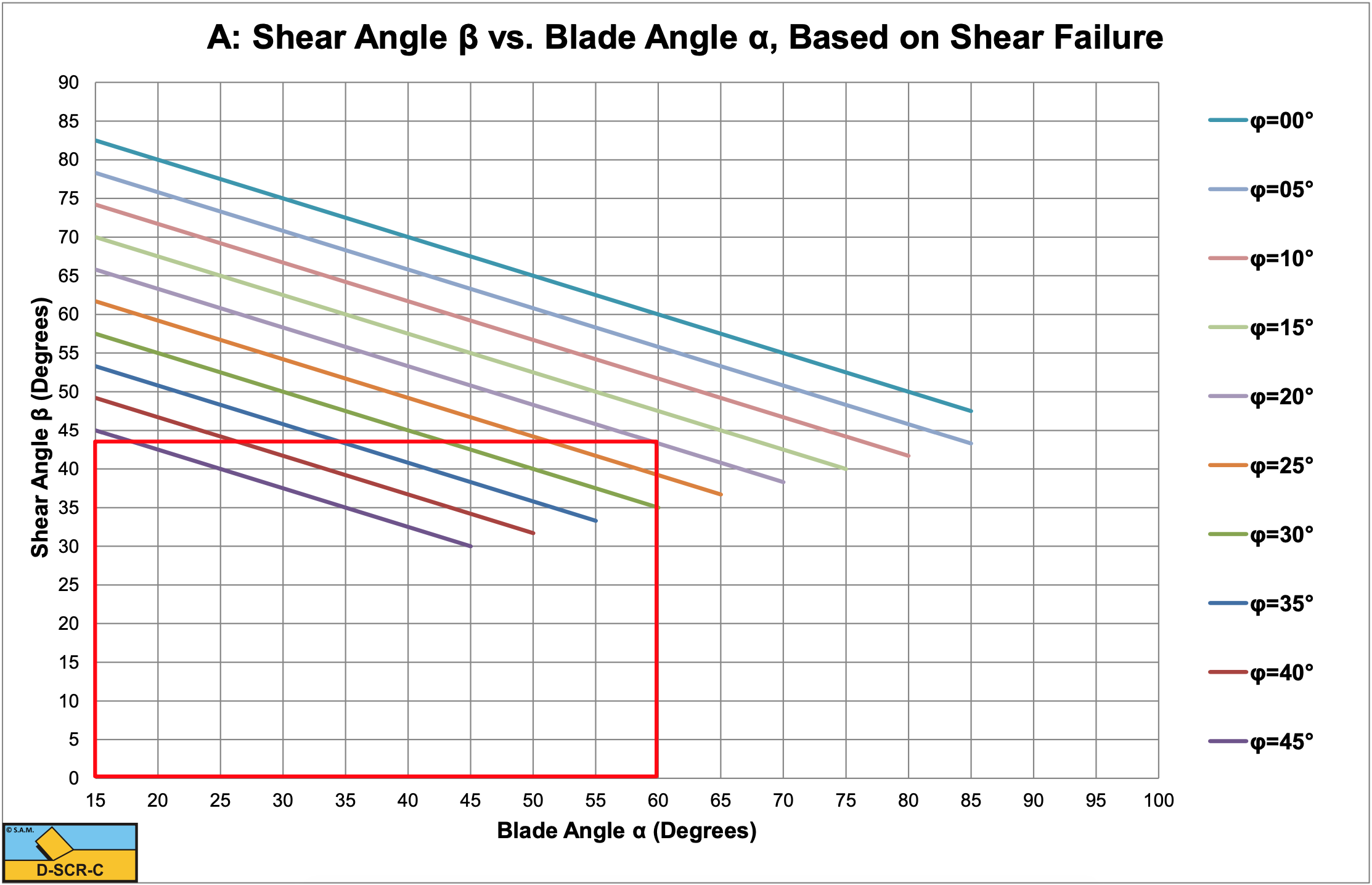
Figure 8-41 shows the shear angle with limitations. The limitations occur because at a certain sum of the blade angle, the shear angle and the angle of internal friction, a positive tensile strength would be required to get brittle tensile failure, which is physically impossible. Compressive stresses are defined positive and tensile stresses negative, so a positive tensile stress would in fact be a compressive stress. Beyond this limitation only brittle shear can exist, or if the sum of the angles is to high, probably another mechanism like the wedge mechanism.