
8.7: Correction on the Tear Type and the Chip Type
- Page ID
- 34843
The equations for the Tear Type are derived based on the shear angle β of the Flow Type. It is however a question whether this is correct under all circumstances. At the moment of transition of Flow Type to Tear Type this may be the case, but far away from this transition there may be another optimum shear angle β. Combining equations (7-68), (7-69) and (7-88) with the shear angle β as a variable and determining the minimum horizontal force, gives a different value for the shear angle β.
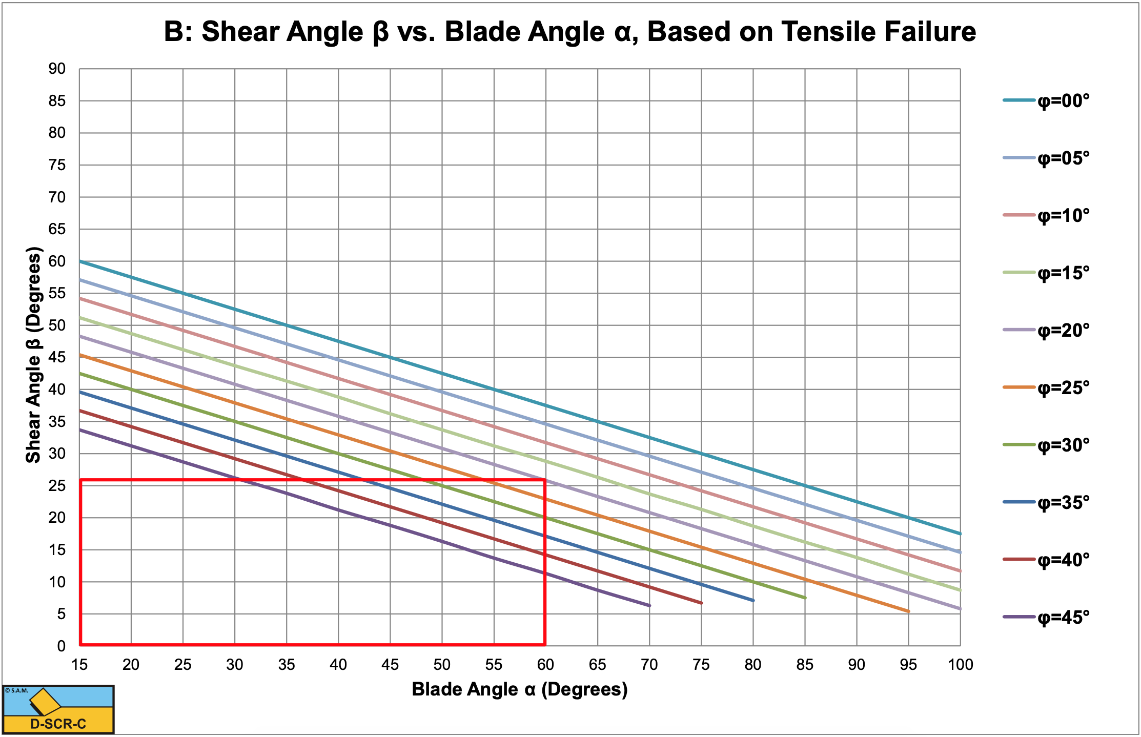
A shear angle β is found, exactly 22.5° smaller than the shear angle β of the Flow Type (see Figure 8-44).
\[\ \beta=\frac{\pi}{2}-\frac{\pi / 4+\alpha+\delta+\varphi}{2}\tag{8-133}\]
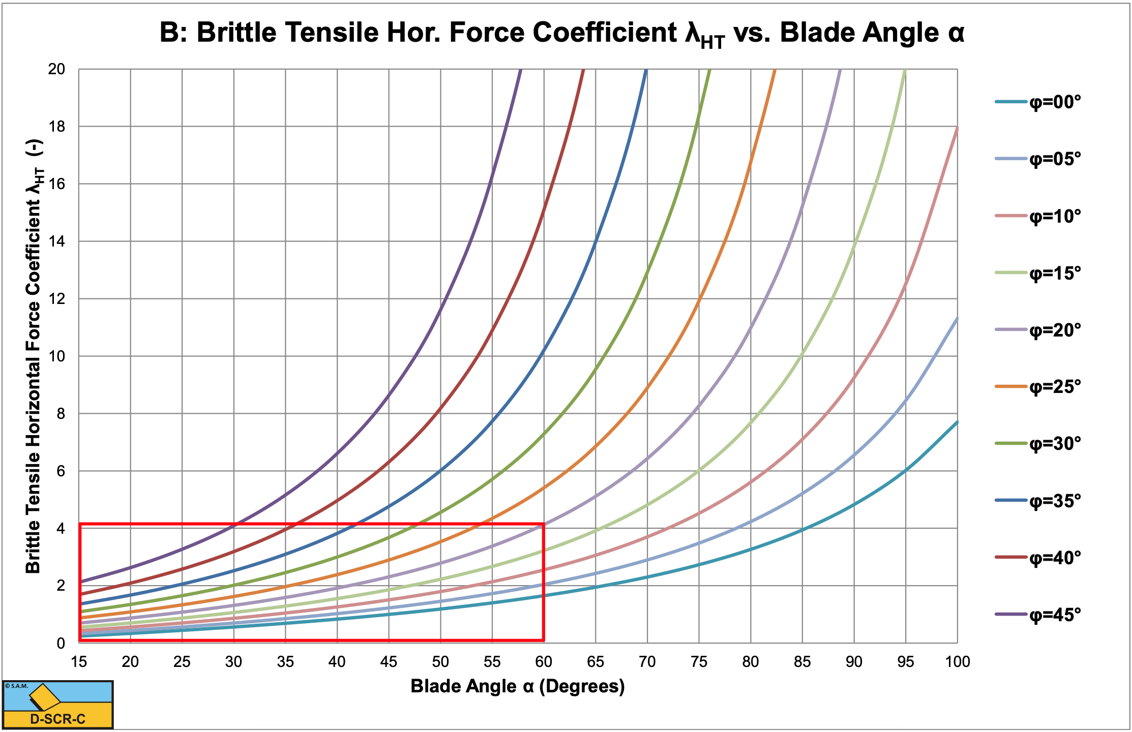
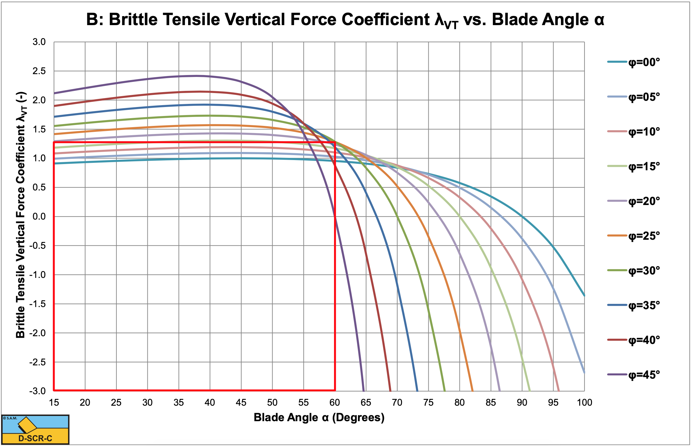
Figure 8-45 and Figure 8-46 show the horizontal and the vertical cutting force coefficients which are slightly smaller than the horizontal and vertical cutting force coefficients in Figure 8-42 and Figure 8-43. Now there exists a set of parameters where both shear failure and tensile failure give a possible solution. In this range of parameters shear failure will not give tensile stresses that exceed the tensile strength while tensile failure would lead to smaller forces. The occurrence of the Flow Type or the Tear Type will depend on the history of the cutting process.
Substituting the corrected shear angle gives for the mobilized shear strength:
\[\ \mathrm{c}_{\mathrm{m}}=\frac{\sigma_{\mathrm{T}}}{\left(\frac{\sin \left(\frac{\alpha+\delta-\varphi-\pi / 4}{2}\right)}{\cos \left(\frac{\alpha+\delta+\varphi-\pi / 4}{2}\right)}-1\right) \cdot\left(\frac{1-\sin (\varphi)}{\cos (\varphi)}\right)}\tag{8-134}\]
Now the cutting forces can be determined with:
\[\ \mathrm{F_{h}=\frac{2 \cdot c_{m} \cdot h_{i} \cdot w \cdot \cos (\varphi) \cdot \sin (\alpha+\delta)}{\cos (\pi / 4)+\cos (\alpha+\delta+\varphi)}=\lambda_{H T} \cdot \sigma_{T} \cdot h_{i} \cdot w}\tag{8-135}\]
\[\ \mathrm{F}_{v}=\frac{\mathrm{2} \cdot \mathrm{c}_{\mathrm{m}} \cdot \mathrm{h}_{\mathrm{i}} \cdot \mathrm{w} \cdot \cos (\varphi) \cdot \cos (\alpha+\delta)}{\cos (\pi / 4)+\cos (\alpha+\delta+\varphi)}=\lambda_{\mathrm{V T}} \cdot \sigma_{\mathrm{T}} \cdot \mathrm{h}_{\mathrm{i}} \cdot \mathrm{w}\tag{8-136}\]