13.2: The Equilibrium of Forces
- Page ID
- 29367

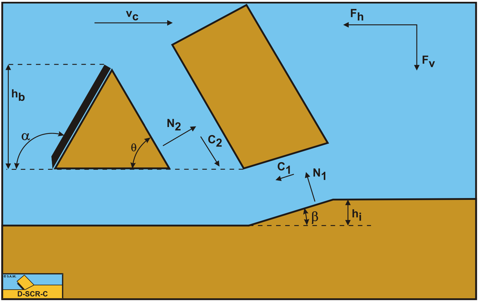
Figure 13-2 illustrates the forces on the layer of soil cut. The forces shown are valid for clay.
The forces acting on the layer A-B are:
-
A normal force acting on the shear surface N1, resulting from the effective grain stresses.
-
A shear force C1 as a result of pure cohesion \(\ \tau_\mathrm{c}\) or shear strength. This force can be calculated by multiplying the cohesive shear strength \(\ \tau_\mathrm{c}\) with the area of the shear plane.
-
A force normal to the pseudo blade N2, resulting from the effective grain stresses.
-
A shear force C2 as a result of the mobilized cohesion between the soil and the wedge \(\ \tau_\mathrm{c}\). This force can be calculated by multiplying the cohesive shear strength \(\ \tau_\mathrm{c}\) of the soil with the contact area between the soil and the wedge.
The forces acting on the wedge front or pseudo blade A-C when cutting clay, can be distinguished as (see Figure 13-3):
-
A force normal to the blade N2, resulting from the effective grain stresses.
-
A shear force C2 as a result of the cohesion between the layer cut and the pseudo blade \(\ \tau_\mathrm{c}\). This force can be calculated by multiplying the cohesive shear strength \(\ \tau_\mathrm{c}\) of the soil with the contact area between the soil and the pseudo blade.
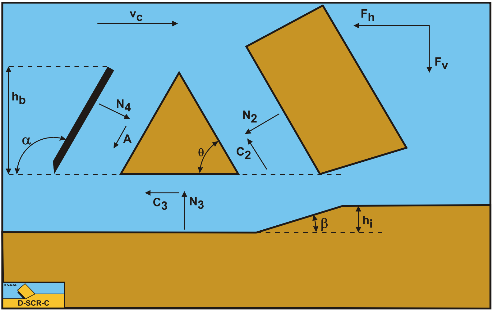
The forces acting on the wedge bottom A-D when cutting clay, can be distinguished as:
-
A force N3, resulting from the effective grain stresses, between the wedge bottom and the undisturbed soil.
-
A shear force C3 as a result of the cohesion between the wedge bottom and the undisturbed soil \(\ \tau_\mathrm{c}\). This force can be calculated by multiplying the cohesive shear strength \(\ \tau_\mathrm{c}\) of the soil with the contact area between the wedge bottom and the undisturbed soil.
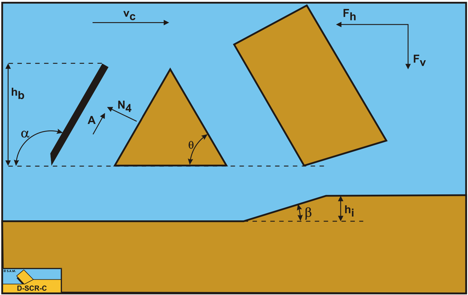
The forces acting on a straight blade C-D when cutting soil (see Figure 13-4), can be distinguished as:
-
A force normal to the blade N4, resulting from the effective grain stresses.
-
A shear force A as a result of pure adhesion between the soil and the blade \(\ \tau_\mathrm{a}\). This force can be calculated by multiplying the adhesive shear strength \(\ \tau_\mathrm{a}\) of the soil with the contact area between the soil and the blade.
The horizontal equilibrium of forces on the layer cut:
\[\ \sum \mathbf{F}_{\mathbf{h}}=\mathbf{N}_{\mathbf{1}} \cdot \sin (\beta)+\mathbf{C}_{\mathbf{1}} \cdot \cos (\beta)-\mathbf{C}_{2} \cdot \cos (\theta)-\mathbf{N}_{2} \cdot \sin (\theta)=0\tag{13-1}\]
The vertical equilibrium of forces on the layer cut:
\[\ \sum \mathbf{F}_{\mathbf{v}}=-\mathbf{N}_{\mathbf{1}} \cdot \cos (\beta)+\mathbf{C}_{\mathbf{1}} \cdot \sin (\beta)+\mathbf{C}_{2} \cdot \sin (\theta)-\mathbf{N}_{2} \cdot \cos (\theta)=\mathbf{0}\tag{13-2}\]
The force N1 on the shear plane is now:
\[\ \mathbf{N}_{1}=\frac{-\mathbf{C}_{1} \cdot \cos (\theta+\beta)+\mathbf{C}_{2}}{\sin (\theta+\beta)}\tag{13-3}\]
The force N2 on the pseudo blade is now:
\[\ \mathbf{N}_{2}=\frac{+\mathbf{C}_{1}-\mathbf{C}_{2} \cdot \cos (\theta+\beta)}{\sin (\theta+\beta)}\tag{13-4}\]
From equation (13-4) the forces on the pseudo blade can be derived. On the pseudo blade a force component in the direction of cutting velocity Fh and a force perpendicular to this direction Fv can be distinguished.
\[\ \mathbf{F}_{\mathbf{h}}=+\mathbf{N}_{\mathbf{2}} \cdot \sin (\theta)+\mathbf{C}_{\mathbf{2}} \cdot \cos (\theta)\tag{13-5}\]
\[\ \mathbf{F}_{v}=+\mathbf{N}_{2} \cdot \cos (\theta)-\mathbf{C}_{2} \cdot \sin (\theta)\tag{13-6}\]
Now knowing the forces on the pseudo blade A-C, the equilibrium of forces on the wedge A-C-D can be derived. The adhesive force does not have to be mobilized 100%, while this force could have both directions, depending on the equilibrium of forces and the equilibrium of moments. So for now the mobilized adhesive force Am is used in the equations.
The horizontal equilibrium of forces on the wedge:
\[\ \mathrm{\sum F_{h}=N_{4} \cdot \sin (\alpha)+A_{m} \cdot \cos (\alpha)-C_{2} \cdot \cos (\theta)-N_{2} \cdot \sin (\theta)-C_{3}=0}\tag{13-7}\]
The vertical equilibrium of forces on the wedge:
\[\ \sum \mathbf{F}_{\mathbf{v}}=\mathbf{N}_{4} \cdot \cos (\alpha)-\mathbf{A}_{\mathbf{m}} \cdot \sin (\alpha)-\mathbf{C}_{2} \cdot \sin (\theta)+\mathbf{N}_{2} \cdot \cos (\theta)-\mathbf{N}_{3}=\mathbf{0}\tag{13-8}\]
To derive N4:
Multiply the horizontal equilibrium equation with sin(α).
\[\ \mathbf{N}_{4} \cdot \sin (\alpha) \cdot \sin (\alpha)+\mathbf{A}_{\mathbf{m}} \cdot \cos (\alpha) \cdot \sin (\alpha)-\mathbf{C}_{2} \cdot \cos (\theta) \cdot \sin (\alpha)-\mathbf{N}_{2} \cdot \sin (\theta) \cdot \sin (\alpha)-\mathbf{C}_{3} \cdot \sin (\alpha)=0\tag{13-9}\]
Multiply the vertical equilibrium equation with cos(α).
\[\ \mathbf{N}_{4} \cdot \cos (\alpha) \cdot \cos (\alpha)-\mathbf{A}_{\mathbf{m}} \cdot \sin (\alpha) \cdot \cos (\alpha)-\mathbf{C}_{2} \cdot \sin (\theta) \cdot \cos (\alpha)
+\mathbf{N}_{2} \cdot \cos (\theta) \cdot \cos (\alpha)-\mathbf{N}_{3} \cdot \cos (\alpha)=\mathbf{0}\tag{13-10}\]
Now add up the two resulting equations in order to get an expression for N4.
\[\ \mathbf{N}_{4}=\mathbf{C}_{2} \cdot \sin (\alpha+\theta)-\mathbf{N}_{2} \cdot \cos (\alpha+\theta)+\mathbf{C}_{3} \cdot \sin (\alpha)+\mathbf{N}_{3} \cdot \cos (\alpha)\tag{13-11}\]
The mobilized adhesive force Am can be derived according to:
First multiply the horizontal equilibrium equation with cos(α).
\[\ \mathbf{N}_{4} \cdot \sin (\alpha) \cdot \cos (\alpha)+\mathbf{A}_{\mathbf{m}} \cdot \cos (\alpha) \cdot \cos (\alpha)-\mathbf{C}_{2} \cdot \cos (\theta) \cdot \cos (\alpha)
-\mathbf{N}_{2} \cdot \sin (\theta) \cdot \cos (\alpha)-\mathbf{C}_{3} \cdot \cos (\alpha)=0\tag{13-12}\]
Now multiply the vertical equilibrium equation with sin(α):
\[\ \mathbf{N}_{4} \cdot \cos (\alpha) \cdot \sin (\alpha)-\mathbf{A}_{\mathbf{m}} \cdot \sin (\alpha) \cdot \sin (\alpha)-\mathbf{C}_{2} \cdot \sin (\theta) \cdot \sin (\alpha)
+\mathbf{N}_{2} \cdot \cos (\theta) \cdot \sin (\alpha)-\mathbf{N}_{3} \cdot \sin (\alpha)=\mathbf{0}\tag{13-13}\]
Subtracting the two resulting equations gives the equation for the mobilized adhesive force.
\[\ \mathbf{A}_{\mathbf{m}}=\mathbf{C}_{2} \cdot \cos (\alpha+\theta)+\mathbf{N}_{2} \cdot \sin (\alpha+\theta)+\mathbf{C}_{3} \cdot \cos (\alpha)-\mathbf{N}_{3} \cdot \sin (\alpha)\tag{13-14}\]
This can also be rewritten as an equation for the normal force N3 on the bottom of the wedge.
\[\ \mathbf{N}_{\mathbf{3}}=\mathbf{N}_{4} \cdot \cos (\alpha)-\mathbf{A}_{\mathbf{m}} \cdot \sin (\alpha)-\mathbf{C}_{2} \cdot \sin (\theta)+\mathbf{N}_{2} \cdot \cos (\theta)\tag{13-15}\]
Since both the mobilized adhesive force Am and the normal force on the bottom of the wedge N3 are unknowns, an additional condition has to be found. The wedge angle θ however is also an unknown, requiring an additional condition. Apparently N4 and Am are independent of each other.