2.6: Soil Mechanical Tests
- Page ID
- 33348
2.6.1. SieveAnalysis
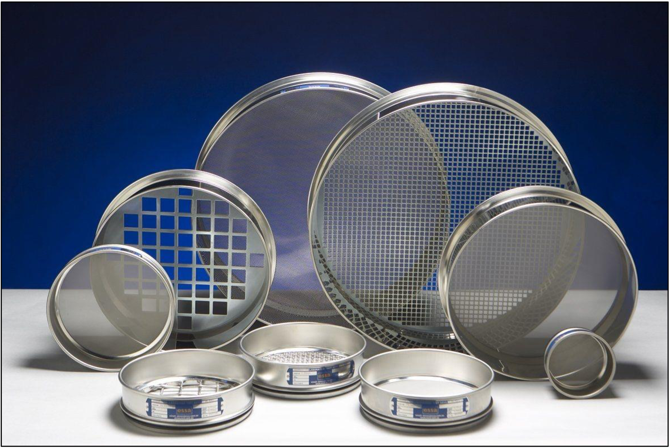
The size distribution of gravel and sand particles are typically measured using sieve analysis. The formal procedure is described in ASTM D6913-04(2009). A stack of sieves with accurately dimensioned holes between a mesh of wires is used to separate the particles into size bins. A known volume of dried soil, with clods broken down to individual particles, is put into the top of a stack of sieves arranged from coarse to fine. The stack of sieves is shaken for a standard period of time so that the particles are sorted into size bins. This method works reasonably well for particles in the sand and gravel size range. Fine particles tend to stick to each other, and hence the sieving process is not an effective method. If there are a lot of fines (silt and clay) present in the soil it may be necessary to run water through the sieves to wash the coarse particles and clods through.
A variety of sieve sizes are available. The boundary between sand and silt is arbitrary. According to the Unified Soil Classification System, a #4 sieve (4 openings per inch) having 4.75mm opening size separates sand from gravel and a #200 sieve with an 0.075 mm opening separates sand from silt and clay. According to the British standard, 0.063 mm is the boundary between sand and silt, and 2 mm is the boundary between sand and gravel.
2.6.2. Hydrometer Analysis
The classification of fine-grained soils, i.e., soils that are finer than sand, is determined primarily by their Atterberg limits, not by their grain size. If it is important to determine the grain size distribution of fine-grained soils, the hydrometer test may be performed. In the hydrometer tests, the soil particles are mixed with water and shaken to produce a dilute suspension in a glass cylinder, and then the cylinder is left to sit. A hydrometer is used to measure the density of the suspension as a function of time. Clay particles may take several hours to settle past the depth of measurement of the hydrometer. Sand particles may take less than a second. Stoke's law provides the theoretical basis to calculate the relationship between sedimentation velocity and particle size. ASTM provides the detailed procedures for performing the Hydrometer test.
Clay particles can be sufficiently small that they never settle because they are kept in suspension by Brownian motion, in which case they may be classified as colloids.
2.6.3. Standard Penetration Test
The standard penetration test (SPT) is an in-situ dynamic penetration test designed to provide information on the geotechnical engineering properties of soil. The test procedure is described in the British Standard BS EN ISO 22476-3, ASTM D1586 and Australian Standards AS 1289.6.3.1.
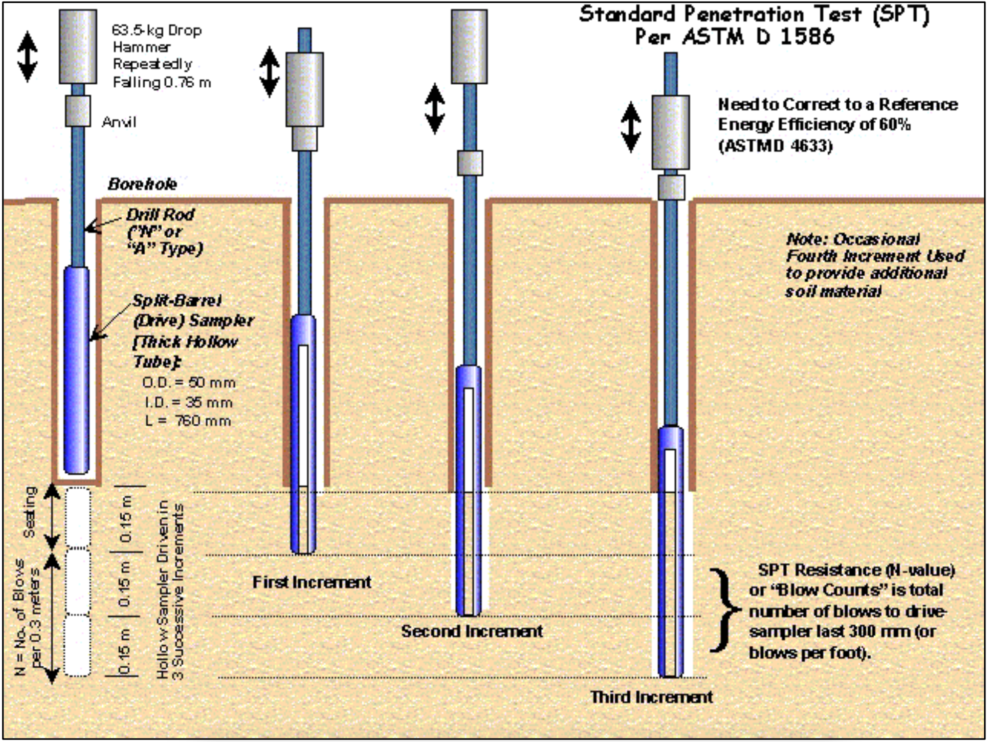
The test uses a thick-walled sample tube, with an outside diameter of 50 mm and an inside diameter of 35 mm, and a length of around 650 mm. This is driven into the ground at the bottom of a borehole by blows from a slide hammer with a weight of 63.5 kg (140 lb) falling through a distance of 760 mm (30 in). The sample tube is driven 150 mm into the ground and then the number of blows needed for the tube to penetrate each 150 mm (6 in) up to a depth of 450 mm (18 in) is recorded. The sum of the number of blows required for the second and third 6 in. of penetration is termed the "standard penetration resistance" or the "N-value". In cases where 50 blows are insufficient to advance it through a 150 mm (6 in) interval the penetration after 50 blows is recorded. The blow count provides an indication of the density of the ground, and it is used in many empirical geotechnical engineering formulae.
The main purpose of the test is to provide an indication of the relative density of granular deposits, such as sands and gravels from which it is virtually impossible to obtain undisturbed samples. The great merit of the test, and the main reason for its widespread use is that it is simple and inexpensive. The soil strength parameters which can be inferred are approximate, but may give a useful guide in ground conditions where it may not be possible to obtain borehole samples of adequate quality like gravels, sands, silts, clay containing sand or gravel and weak rock. In conditions where the quality of the undisturbed sample is suspect, e.g. very silty or very sandy clays, or hard clays, it is often advantageous to alternate the sampling with standard penetration tests to check the strength. If the samples are found to be unacceptably disturbed, it may be necessary to use a different method for measuring strength like the plate test. When the test is carried out in granular soils below groundwater level, the soil may become loosened. In certain circumstances, it can be useful to continue driving the sampler beyond the distance specified, adding further drilling rods as necessary. Although this is not a standard penetration test, and should not be regarded as such, it may at least give an indication as to whether the deposit is really as loose as the standard test may indicate.
The usefulness of SPT results depends on the soil type, with fine-grained sands giving the most useful results, with coarser sands and silty sands giving reasonably useful results, and clays and gravelly soils yielding results which may be very poorly representative of the true soil conditions. Soils in arid areas, such as the Western United States, may exhibit natural cementation. This condition will often increase the standard penetration value.
The SPT is used to provide results for empirical determination of a sand layer's susceptibility to earthquake liquefaction, based on research performed by Harry Seed, T. Leslie Youd, and others.
Despite its many flaws, it is usual practice to correlate SPT results with soil properties relevant for geotechnical engineering design. The reason being that SPT results are often the only test results available, therefore the use of direct correlations has become common practice in many countries.
Different correlations are proposed for granular and cohesive soils.
2.6.4. Cone Penetration Test
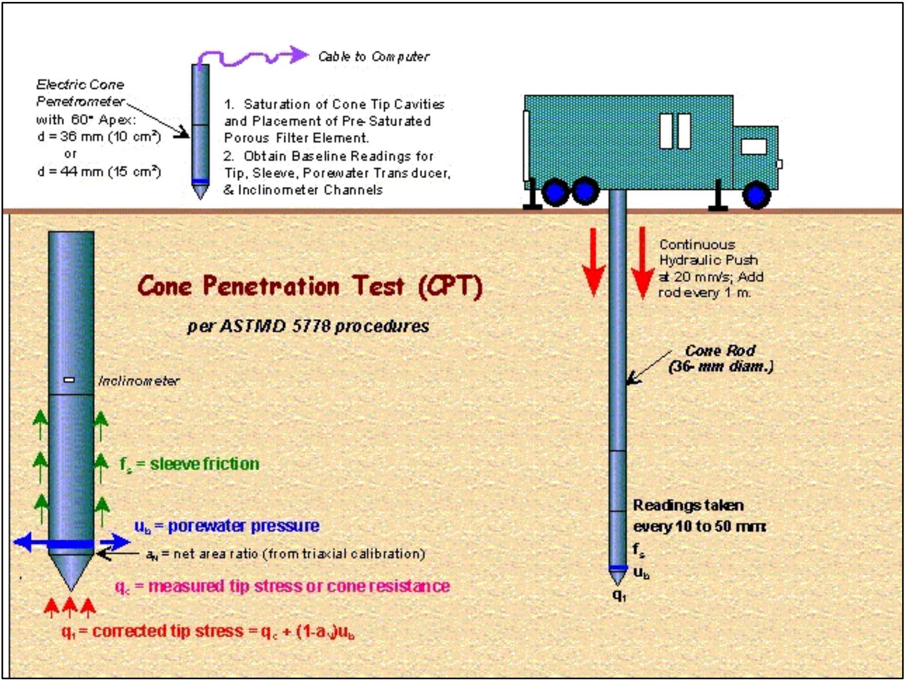
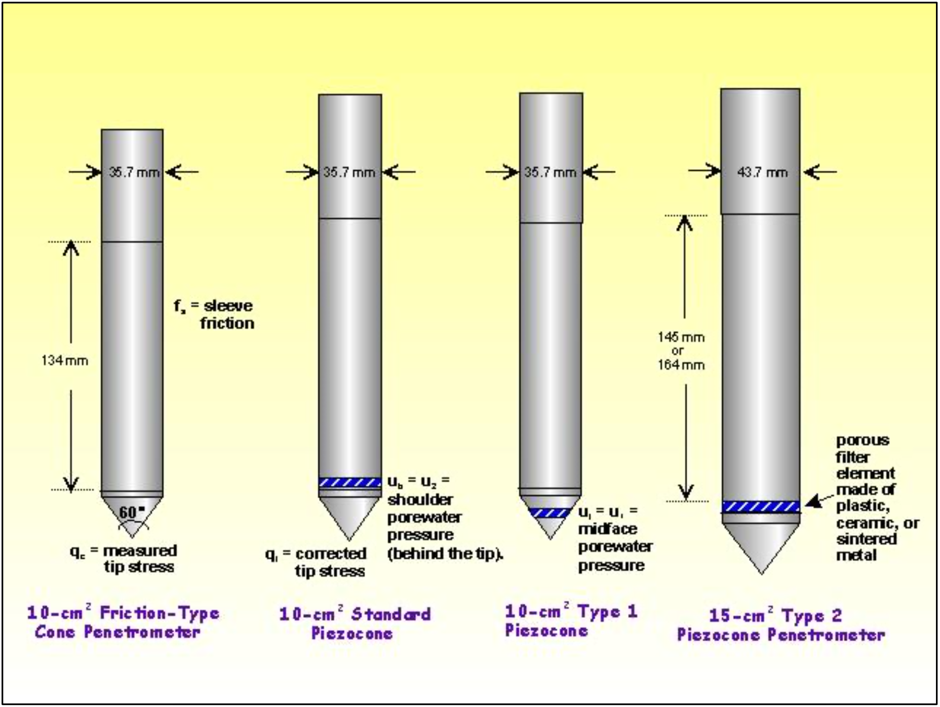
The cone penetration test (CPT) is an in situ testing method used to determine the geotechnical engineering properties of soils and delineating soil stratigraphy. It was initially developed in the 1950s at the Dutch Laboratory for Soil Mechanics in Delft to investigate soft soils. Based on this history it has also been called the "Dutch cone test". Today, the CPT is one of the most used and accepted in situ test methods for soil investigation worldwide. The test method consists of pushing an instrumented cone, with the tip facing down, into the ground at a controlled rate (usually 2 centimeters/second). The resolution of the CPT in delineating stratigraphic layers is related to the size of the cone tip, with typical cone tips having a cross-sectional area of either 10 or 15 cm2, corresponding to diameters of 3.6 and 4.4 cm.
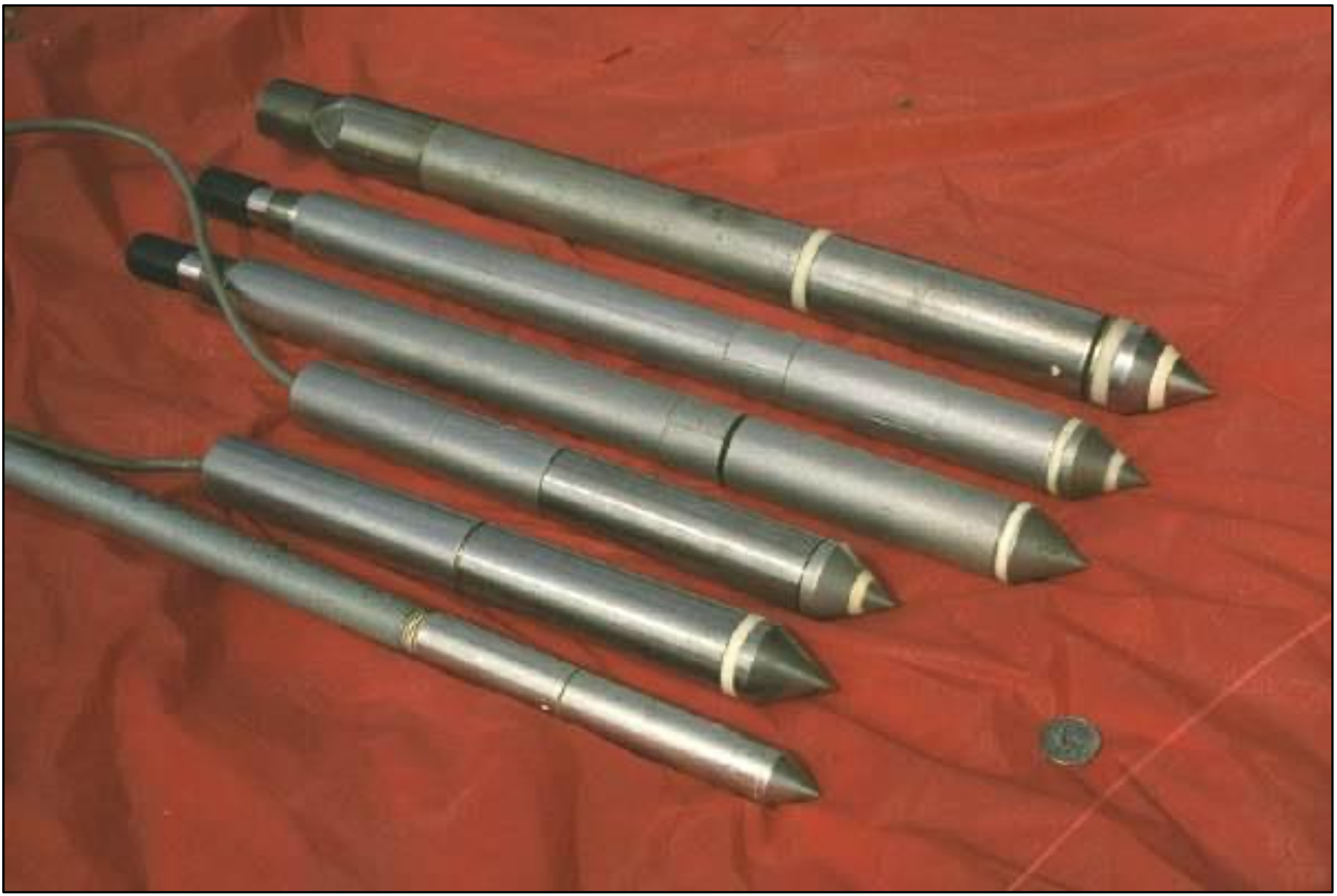
The early applications of CPT mainly determined the soil geotechnical property of bearing capacity. The original cone penetrometers involved simple mechanical measurements of the total penetration resistance to pushing a tool with a conical tip into the soil. Different methods were employed to separate the total measured resistance into components generated by the conical tip (the "tip friction") and friction generated by the rod string. A friction sleeve was added to quantify this component of the friction and aid in determining soil cohesive strength in the 1960s (Begemann, 1965). Electronic measurements began in 1948 and improved further in the early 1970s (de Reister, 1971). Most modern electronic CPT cones now also employ a pressure transducer with a filter to gather pore water pressure data. The filter is usually located either on the cone tip (the so-called U1 position), immediately behind the cone tip (the most common U2 position) or behind the friction sleeve (U3 position). Pore water pressure data aids determining stratigraphy and is primarily used to correct tip friction values for those effects. CPT testing which also gathers this piezometer data is called CPTU testing. CPT and CPTU testing equipment generally advances the cone using hydraulic rams mounted on either a heavily ballasted vehicle or using screwed-in anchors as a counter-force. One advantage of CPT over the Standard Penetration Test (SPT) is a more continuous profile of soil parameters, with CPTU data recorded typically at 2cm intervals.
In addition to the mechanical and electronic cones, a variety of other CPT-deployed tools have been developed over the years to provide additional subsurface information. One common tool advanced during CPT testing is a geophone set to gather seismic shear wave and compression wave velocities. This data helps determine the shear modulus and Poisson's ratio at intervals through the soil column for soil liquefaction analysis and low-strain soil strength analysis. Engineers use the shear wave velocity and shear modulus to determine the soil's behavior under low-strain and vibratory loads. Additional tools such as laser-induced fluorescence, X-ray fluorescence [1], soil conductivity/resistivity, membrane interface probe and cameras for capturing video imagery are also increasingly advanced in conjunction with the CPT probe. An additional CPT deployed tool used in Britain, Netherlands, Germany, Belgium and France is a piezocone combined with a tri-axial magnetometer. This is used to attempt to ensure that tests, boreholes, and piles, do not encounter unexploded ordnance (UXB) or duds. The magnetometer in the cone detects ferrous materials of 50 kg or larger within a radius of up to about 2 m distance from the probe depending on the material, orientation and soil conditions.
CPT for geotechnical applications was standardized in 1986 by ASTM Standard D 3441 (ASTM, 2004). ISSMGE provides international standards on CPT and CPTU. Later ASTM Standards have addressed the use of CPT for various environmental site characterization and groundwater monitoring activities. Particularly for geotechnical soil investigations, CPT is gaining popularity compared to standard penetration testing as a method of geotechnical soil investigation by its increased accuracy, speed of deployment, more continuous soil profile and reduced cost over other soil testing methods. The ability to advance additional in situ testing tools using the CPT direct push drilling rig, including the seismic tools described above, are accelerating this process.
2.6.5. Triaxial Test
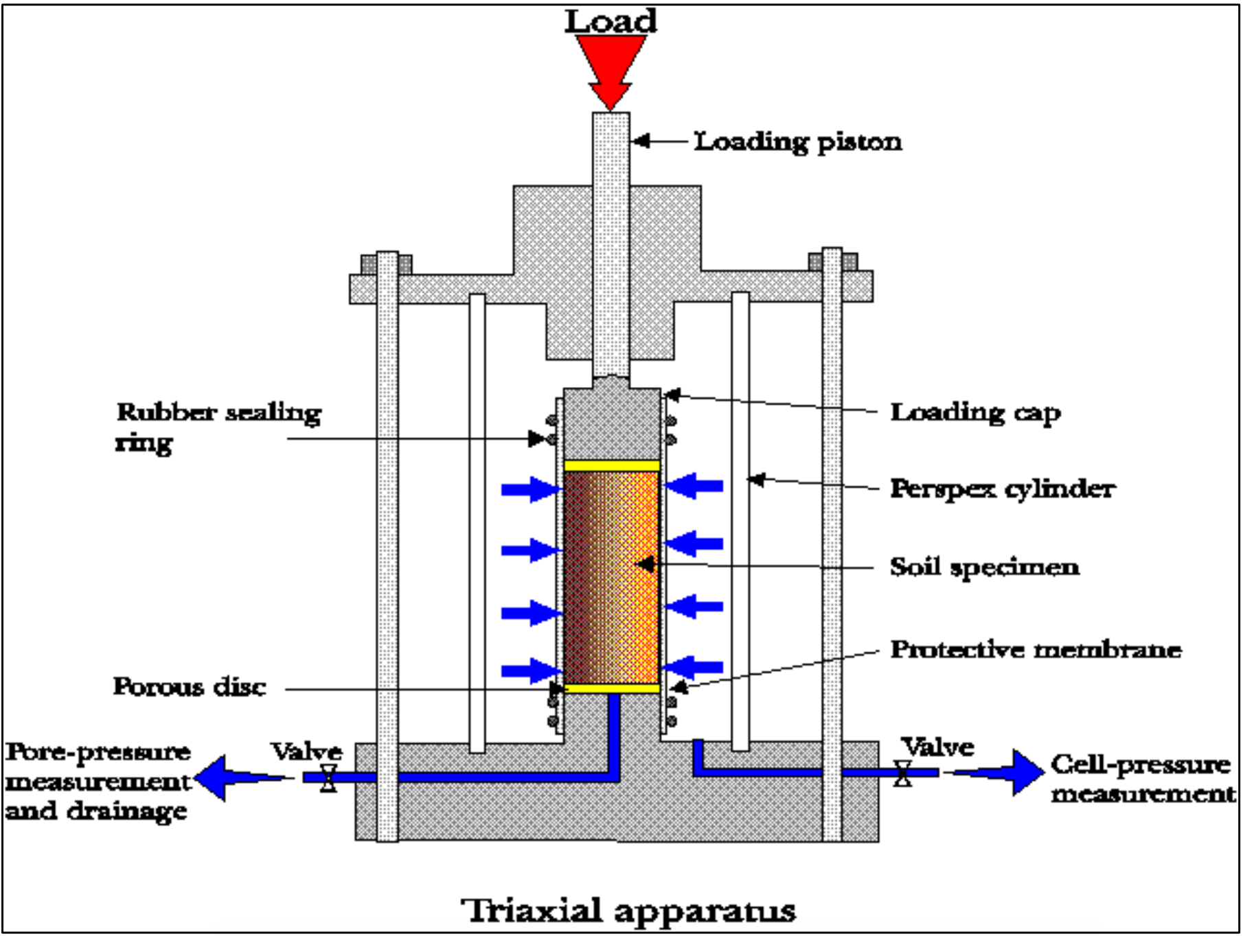
A triaxial shear test is a common method to measure the mechanical properties of many deformable solids, especially soil (e.g. sand, clay) and rock, and other granular materials or powders. There are several variations on the test. Although the name triaxial test suggests that the stresses would be different in three directions, this is not true in the test as is usually done. In this test with oil or water as confining medium, the confining pressures are equal in all directions (i.e. in terms of principal stresses: for a compression test: σ1 ≠ σ2 = σ3 and for tensile: σ1 = σ2 ≠ σ3). Only in a true triaxial test the stresses in all three directions can be different (i.e. σ1 ≠ σ2 ≠ σ3). For loose granular materials like sand or gravel, the material is contained in a cylindrical latex sleeve with a flat, circular metal plate or platen closing off the top and bottom ends. This cylinder is placed into a bath of water (mostly water but may be any other fluid) to provide pressure along the sides of the cylinder. The top platen can then be mechanically driven up or down along the axis of the cylinder to squeeze the material. The distance that the upper platen travels is measured as a function of the force required to move it, as the pressure of the surrounding water is carefully controlled. The net change in volume of the material is also measured by how much water moves in or out of the surrounding bath. The test for cohesive (non-loose) materials (e.g. clay, rock) is similar to the test for loose granular materials. For rock testing the sleeve may be a thin metal sheeting rather than latex. Triaxial testing on rock is fairly seldom done because the high forces and pressures required to break a rock sample imply very costly and cumbersome testing equipment available at few laboratories in the world. During the test the pore pressures of fluids (e.g. water, oil) or gasses in the sample may be measured.
The principle behind a triaxial shear test is that the stress applied in the vertical direction (along the axis of the cylindrical sample) can be different from the stresses applied in the horizontal directions perpendicular to the sides of the cylinder, i.e. the confining pressure). In a homogeneous and isotropic material this produces a non- hydrostatic stress state, with shear stress that may lead to failure of the sample in shear. In non-homogeneous and anisotropic samples (e.g. bedded or jointed samples) failure may occur due to bending moments and, hence, failure may be tensile. Also combinations of bending and shear failure may happen in inhomogeneous and anisotropic material.
A solid is defined as a material that can support shear stress without moving. However, every solid has an upper limit to how much shear stress it can support. The triaxial test is designed to measure that limit. The stress on the platens is increased until the material in the cylinder fails and forms sliding regions within itself, known as shear bands. A motion where a material is deformed under shear stress is known as shearing. The geometry of the shearing in a triaxial test typically causes the sample to become shorter while bulging out along the sides. The stress on the platen is then reduced and the water pressure pushes the sides back in, causing the sample to grow taller again. This cycle is usually repeated several times while collecting stress and strain data about the sample. During the shearing, a granular material will typically have a net gain or loss of volume. If it had originally been in a dense state, then it typically gains volume, a characteristic known as Reynolds' dilatancy. If it had originally been in a very loose state, then contraction may occur before the shearing begins or in conjunction with the shearing.
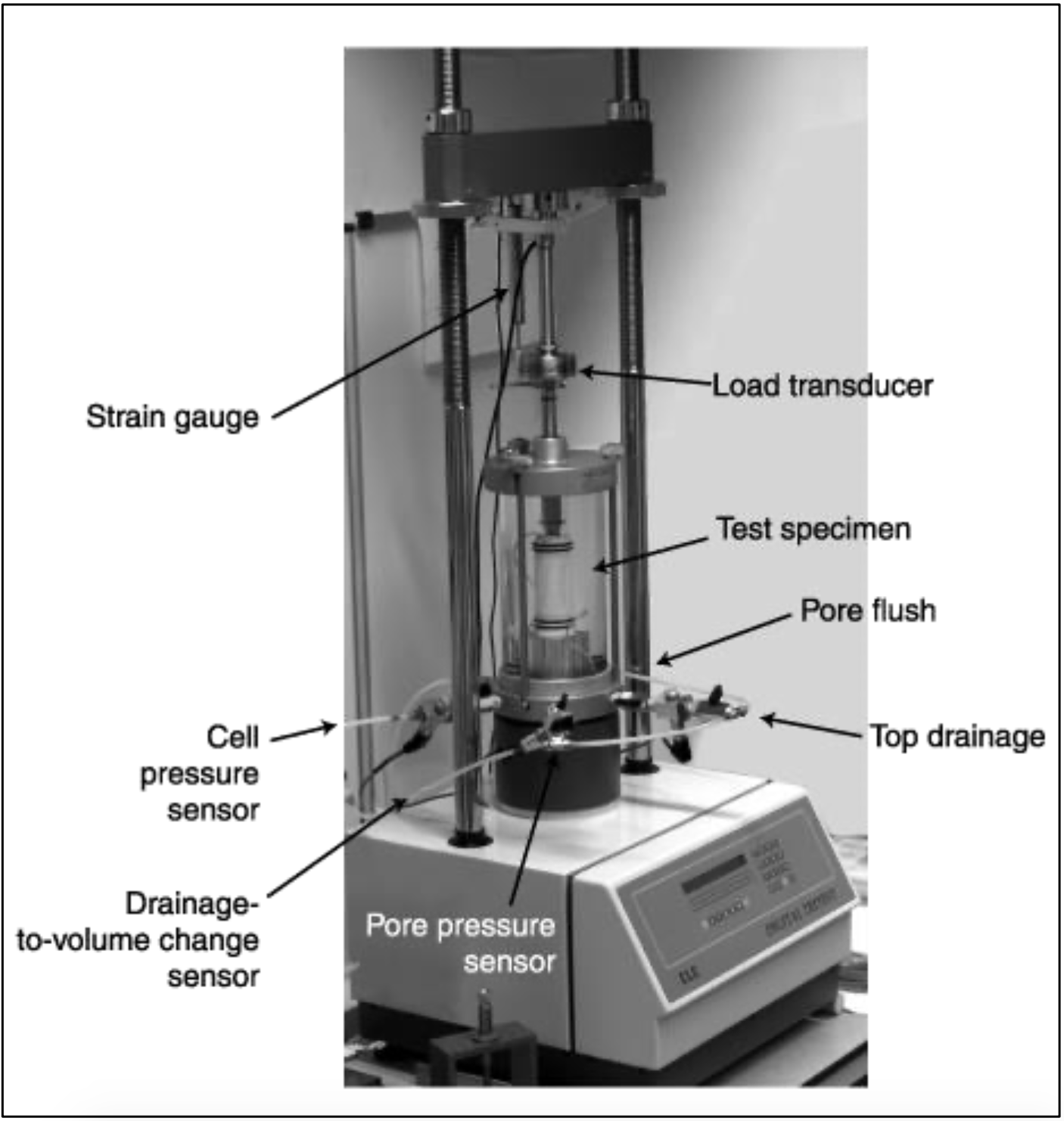
From the triaxial test data, it is possible to extract fundamental material parameters about the sample, including its angle of shearing resistance, apparent cohesion, and dilatancy angle. These parameters are then used in computer models to predict how the material will behave in a larger-scale engineering application. An example would be to predict the stability of the soil on a slope, whether the slope will collapse or whether the soil will support the shear stresses of the slope and remain in place. Triaxial tests are used along with other tests to make such engineering predictions.
The triaxial test can be used to determine the shear strength of a discontinuity. A homogeneous and isotropic sample (see above) fails due to shear stresses in the sample. If a sample with a discontinuity is orientated such that the discontinuity is about parallel to the plane in which maximum shear stress will be developed during the test, the sample will fail due to shear displacement along the discontinuity, and hence, the shear strength of a discontinuity can be calculated.
There are several variations of the triaxial test:
2.6.5.1. Consolidated Drained (CD)
In a consolidated drained test the sample is consolidated and sheared in compression with drainage. The rate of axial deformation is kept constant, i.e. is strain controlled. The idea is that the test allows the sample and the pore pressures to fully consolidate (i.e. adjust) to the surrounding stresses. The test may take a long time to allow the sample to adjust, in particular low permeability samples need a long time to drain and adjust stain to stress levels.
2.6.5.2. Consolidated Undrained (CU)
In a consolidated undrained test the sample is not allowed to drain. The shear characteristics are measured under undrained conditions and the sample is assumed to be fully consolidated under the stresses applied that should be similar to the field conditions. Test in particular used if a change in stress is to happen without time for further consolidation.
2.6.5.3. Unconsolidated Undrained (UU)
In an unconsolidated undrained test the sample is not allowed to drain. The sample is compressed at a constant rate (strain-controlled).
2.6.6. ShearTest
A direct shear test also known as shear box test is a laboratory or field test used by geotechnical engineers to measure the shear strength properties of soil or rock material, or of discontinuities in soil or rock masses. For soil the U.S. and U.K. standards defining how the test should be performed are ASTM D 3080 and BS 1377-7:1990 respectively to establish the shear strength properties of soil. It is also possible to estimate typical values of the shear strength parameters based on the type and classification of the soils. For rock the test is generally restricted to rock with (very) low (shear) strength. The test is, however, standard practice to establish the shear strength properties of discontinuities in rock.
The test is performed on three or four specimens from a relatively undisturbed soil sample. A specimen is placed in a shear box which has two stacked rings to hold the sample; the contact between the two rings is at approximately the mid-height of the sample. A confining stress is applied vertically to the specimen, and the upper ring is pulled laterally until the sample fails, or through a specified strain. The load applied and the strain induced is recorded at frequent intervals to determine a stress-strain curve for the confining stress.
Direct Shear tests can be performed under several conditions. The sample is normally saturated before the test is run, but can be run at the in-situ moisture content. The rate of strain can be varied to create a test of undrained or drained conditions, depending whether the strain is applied slowly enough for water in the sample to prevent pore- water pressure buildup.
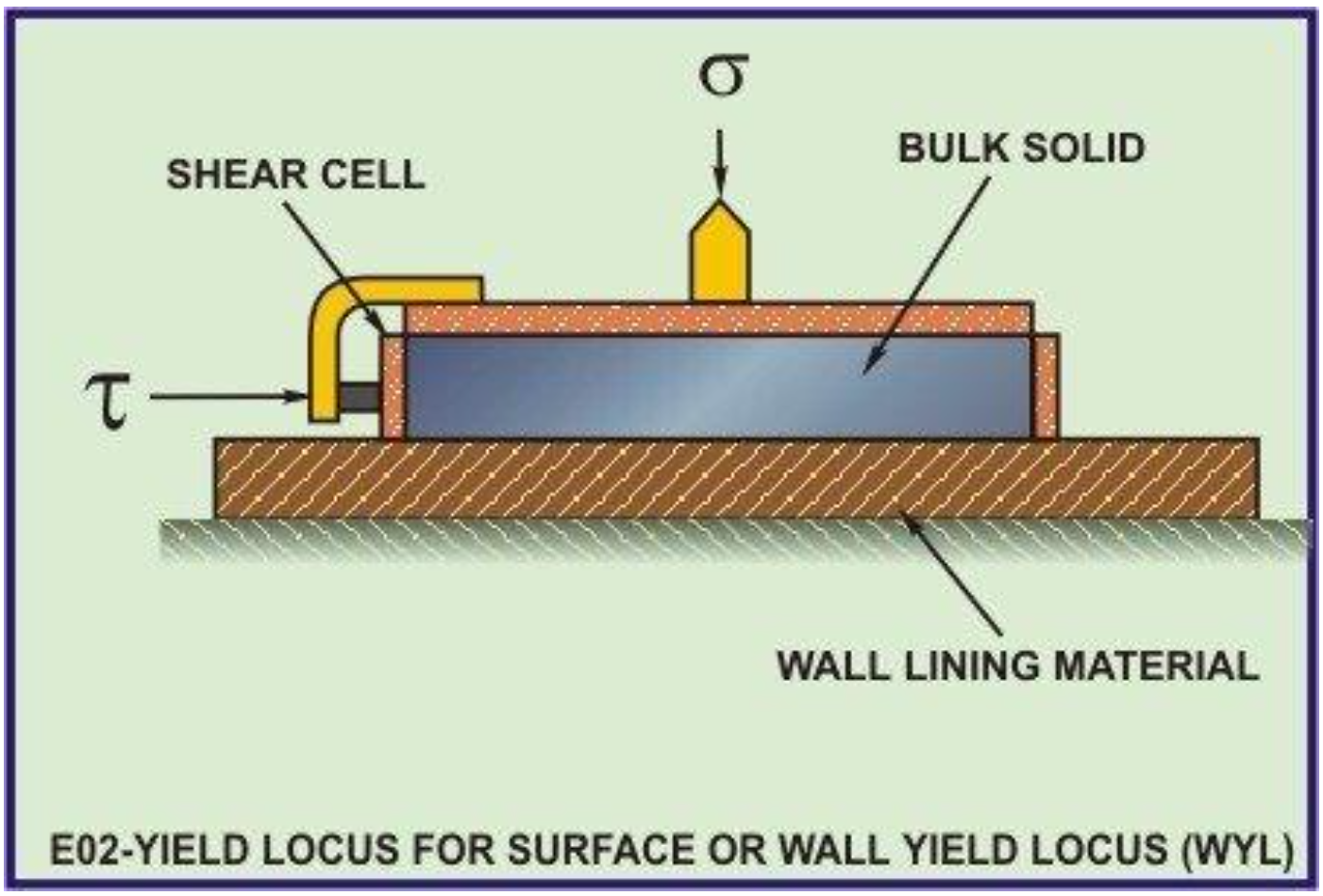
Several specimens are tested at varying confining stresses to determine the shear strength parameters, the soil cohesion (c) and the angle of internal friction (commonly friction angle) (φ). The results of the tests on each specimen are plotted on a graph with the peak (or residual) stress on the x-axis and the confining stress on the y- axis. The y-intercept of the curve which fits the test results is the cohesion, and the slope of the line or curve is the friction angle.
2.6.7. PointLoadTest
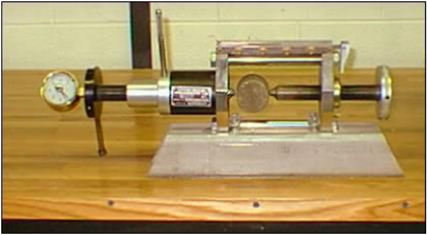
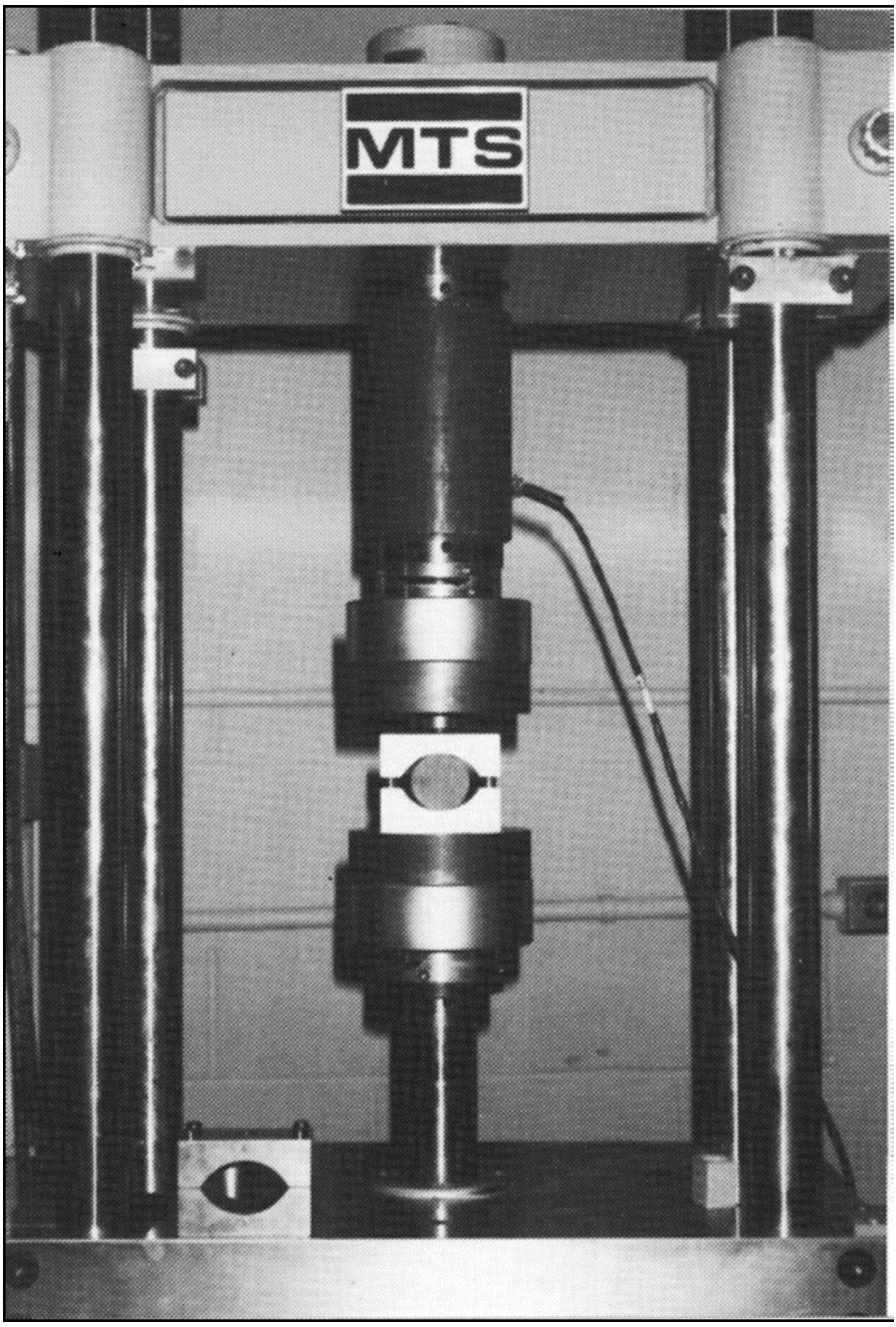
The Point Load Strength test is intended as an index test for the strength classification of rock materials. It may also be used to predict other strength parameters with which it is correlated, for example the unconfined compressive and the tensile strength. It is measured in accordance with the procedures recommended in ASTM D5731, usually with NX-size core samples. The testing machine consists of a loading frame, which measures the force required to break the sample, and a system for measuring the distance between the two platen contact points. Rock specimens in the form of either core, cut blocks, or irregular lumps are broken by application of concentrated load through a pair of spherically truncated, conical platens. The applied force at failure of the sample and distance between the platen tips are recorded in order to calculate the point load index as follows:
\[\ \mathrm{I}_{\mathrm{s}}=\frac{\mathrm{F}}{\mathrm{D}_{\mathrm{e}}^{2}}\tag{2-44}\]
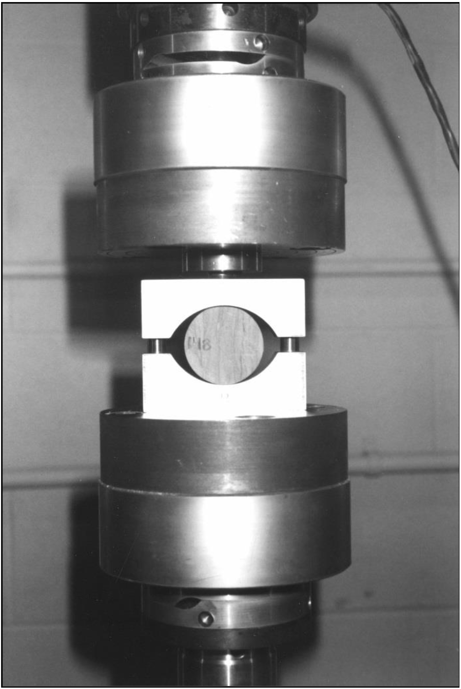
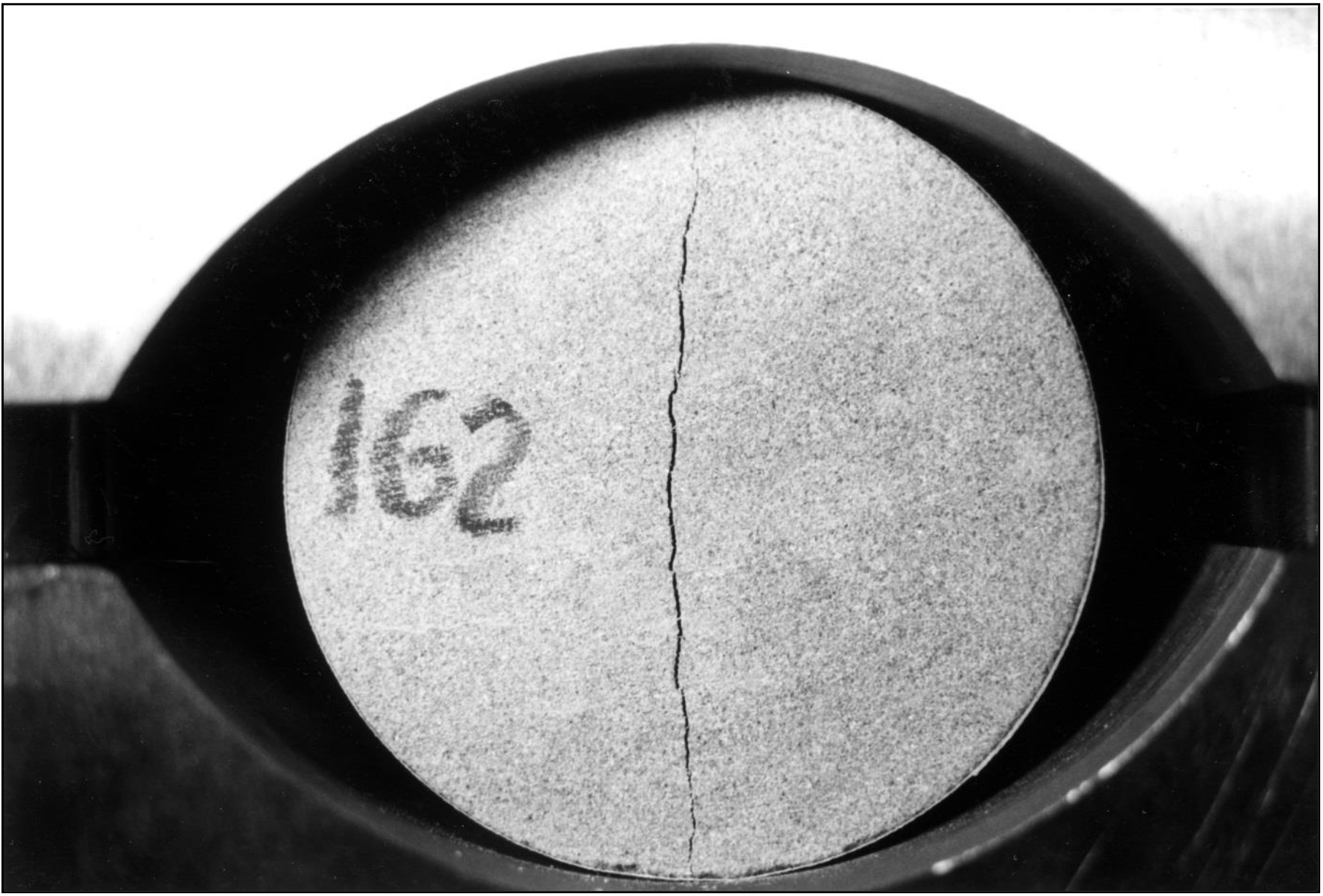
Another test that is familiar with the Brazilian splitting test is the point load strength test. This test is executed either axial, diametrical or on irregular pieces. The point load test is frequently used to determine the strength when a large number of samples have to be tested. The tests give for brittle rocks, when tested under diametric loading, values reasonable close to the BTS. Also it is suggested that PLS=0.8*BTS, it is suggested to establish such a relation based on both tests.
