
5.3: The Equilibrium of Forces
- Page ID
- 29445

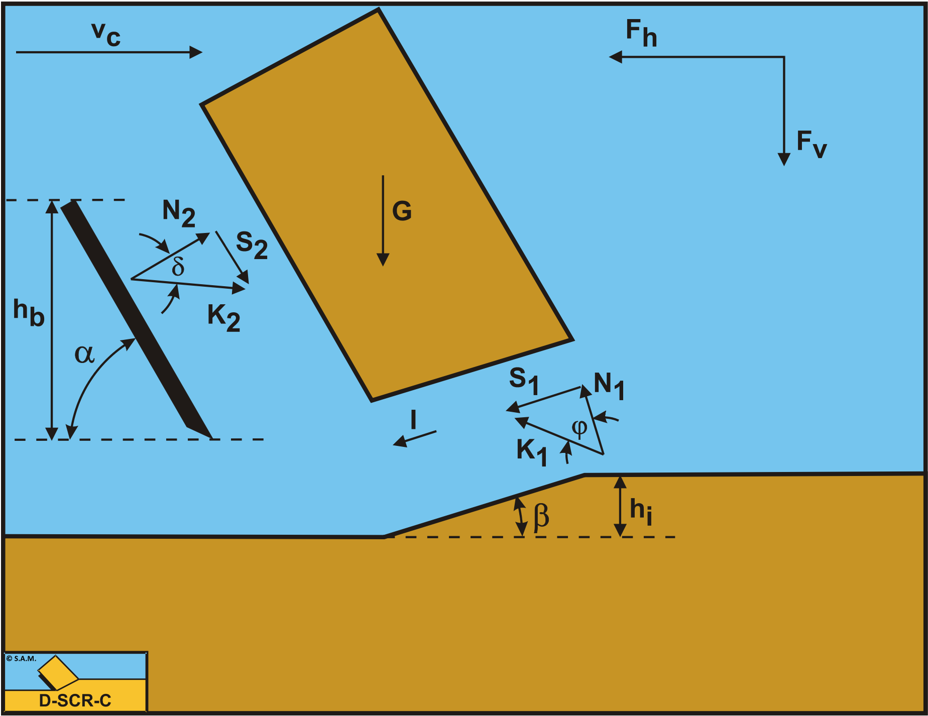
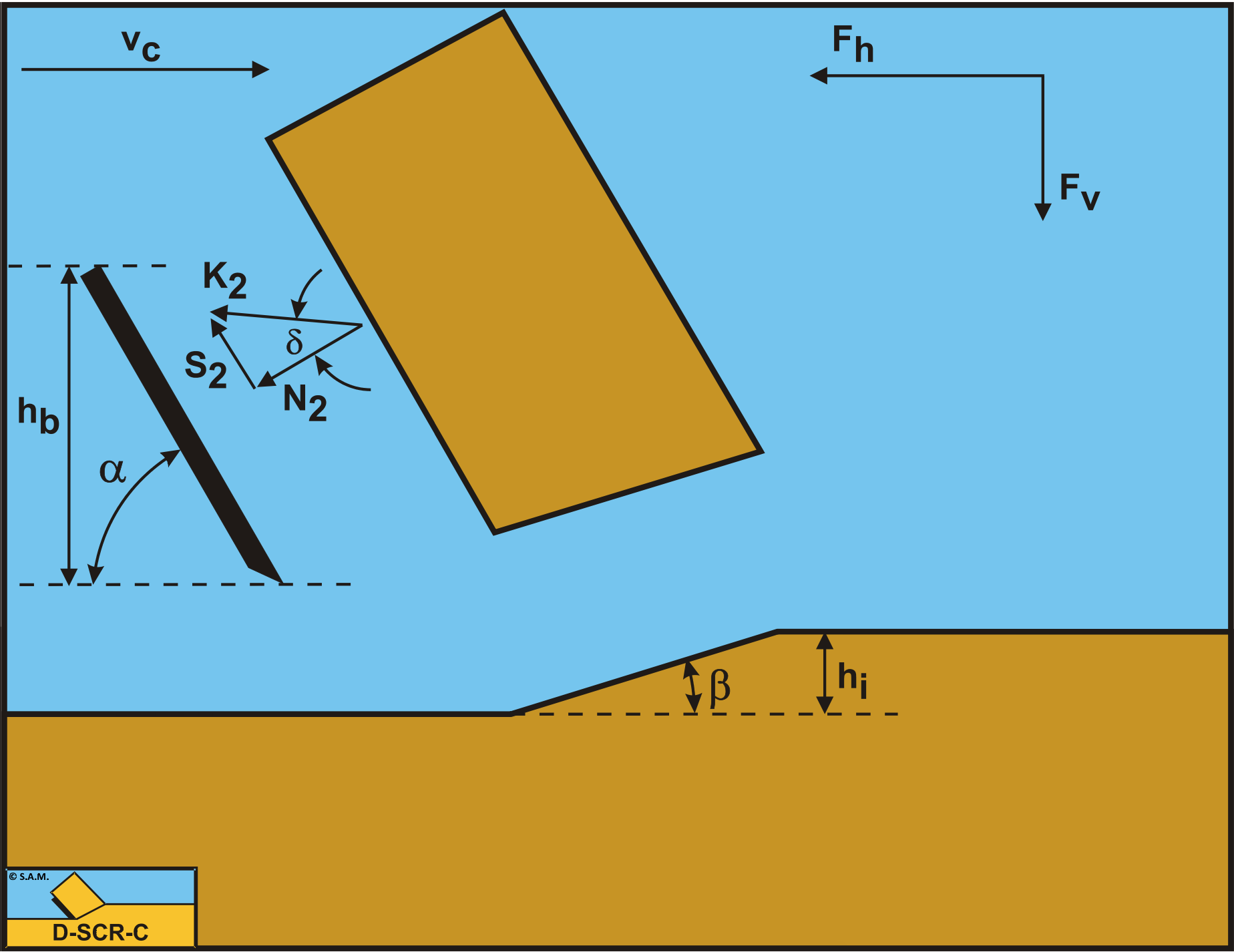
Figure 5-4 illustrates the forces on the layer of soil cut. The forces shown are valid in general. The forces acting on this layer are:
-
A normal force acting on the shear surface N1, resulting from the effective grain stresses.
-
A shear force S1 as a result of internal friction, N1·tan(φ).
-
A gravity force G as a result of the weight of the layer cut.
-
An inertial force I, resulting from acceleration of the soil.
-
A force normal to the blade N2, resulting from the effective grain stresses.
-
A shear force S2 as a result of the soil/steel friction N2·tan(δ).
The normal force N1 and the shear force S1 can be combined to a resulting grain force K1.
\[\ \mathrm{K}_{1}=\sqrt{\mathrm{N}_{1}^{2}+\mathrm{S}_{1}^{2}}\tag{5-1}\]
The forces acting on a straight blade when cutting soil, can be distinguished as:
-
A force normal to the blade N2, resulting from the effective grain stresses.
-
A shear force S2 as a result of the soil/steel friction N2·tan(δ).
These forces are shown in Figure 5-5. If the forces N2 and S2 are combined to a resulting force K2 and the adhesive force and the water under pressures are known, then the resulting force K2 is the unknown force on the blade. By taking the horizontal and vertical equilibrium of forces an expression for the force K2 on the blade can be derived.
\[\ \mathrm{K}_{2}=\sqrt{\mathrm{N}_{2}^{2}+\mathrm{S}_{2}^{2}}\tag{5-2}\]
Pure sand is supposed to be cohesion less, meaning it does not have shear strength or the shear strength is zero and the adhesion is also zero. The shear stresses, internal and external, depend completely on the normal stresses. In dry sand the pores between the sand grains are filled with air and although dilatation will occur due to shearing, Miedema (1987 September), there will be hardly any generation of pore under pressures because the permeability for air flowing through the pores is high. This means that the cutting forces do not depend on pore pressure forces, nor on adhesion and cohesion, but only on gravity and inertia, resulting in the following set of equations:
The horizontal equilibrium of forces:
\[\ \mathrm{ \sum F_{h}=K_{1} \cdot \sin (\beta+\varphi)+I \cdot \cos (\beta)-K_{2} \cdot \sin (\alpha+\delta)=0}\tag{5-3}\]
The vertical equilibrium of forces:
\[\ \sum \mathrm{F}_{\mathrm{v}}=-\mathrm{K}_{\mathrm{1}} \cdot \cos (\beta+\varphi)+\mathrm{I} \cdot \sin (\beta)+\mathrm{G}-\mathrm{K}_{2} \cdot \cos (\alpha+\delta)=\mathrm{0}\tag{5-4}\]
The force K1 on the shear plane is now:
\[\ \mathrm{K}_{1}=\frac{\mathrm{G} \cdot \sin (\alpha+\delta)-\mathrm{I} \cdot \cos (\alpha+\beta+\delta)}{\sin (\alpha+\beta+\delta+\varphi)}\tag{5-5}\]
The force K2 on the blade is now:
\[\ \mathrm{K}_{2}=\frac{\mathrm{G} \cdot \sin (\beta+\varphi)+\mathrm{I} \cdot \cos (\varphi)}{\sin (\alpha+\beta+\delta+\varphi)}\tag{5-6}\]
Wismer and Luth (1972A) and (1972B) researched the inertia forces part of the total cutting forces. The following equation is derived:
\[\ \mathrm{I}=\rho_{\mathrm{s}} \cdot \mathrm{v}_{\mathrm{c}}^{2} \cdot \frac{\sin (\alpha)}{\sin (\alpha+\beta)} \cdot \mathrm{h}_{\mathrm{i}} \cdot \mathrm{w}\tag{5-7}\]
The gravitational force (weight dry) follows, based on Figure 5-2, from:
\[\ \mathrm{G}=\rho_{\mathrm{s}} \cdot \mathrm{g} \cdot \mathrm{h}_{\mathrm{i}} \cdot \mathrm{w} \cdot \frac{\sin (\alpha+\beta)}{\sin (\beta)} \cdot\left\{\frac{\left(\mathrm{h}_{\mathrm{b}}+\mathrm{h}_{\mathrm{i}} \cdot \sin (\alpha)\right)}{\sin (\alpha)}+\frac{\mathrm{h}_{\mathrm{i}} \cdot \cos (\alpha+\beta)}{2 \cdot \sin (\beta)}\right\}\tag{5-8}\]
In reality the shape of the layer cut may be different since there is no force to keep the sand together and the maximum slope of the sand will be dependent on the angle of natural repose. For the calculations the above equation is applied, since this equation is used for all soil types. Other formulations for the weight of the soil may be used. From equation (5-6) the forces on the blade can be derived. On the blade a force component in the direction of cutting velocity Fh and a force perpendicular to this direction Fv can be distinguished.
\[\ \mathrm{F}_{\mathrm{h}}=\mathrm{K}_{2} \cdot \sin (\alpha+\delta)\tag{5-9}\]
\[\ \mathrm{F}_{v}=\mathrm{K}_{2} \cdot \cos (\alpha+\delta)\tag{5-10}\]
The normal force on the shear plane is now:
\[\ \mathrm{N}_{1}=\frac{\mathrm{G} \cdot \sin (\alpha+\delta)-\mathrm{I} \cdot \cos (\alpha+\beta+\delta)}{\sin (\alpha+\beta+\delta+\varphi)} \cdot \cos (\varphi)\tag{5-11}\]
The normal force on the blade is now:
\[\ \mathrm{N}_{2}=\frac{\mathrm{G} \cdot \sin (\beta+\varphi)+\mathrm{I} \cdot \cos (\varphi)}{\sin (\alpha+\beta+\delta+\varphi)} \cdot \cos (\delta)\tag{5-12}\]
Equations (5-11) and (5-12) show that the normal force on the shear plane N1 can become negative at very high velocities, which are physically impossible, while the normal force on the blade N2 will always be positive. Under normal conditions the sum of α+β+δ will be greater than 90 degrees in which case the cosine of this sum is negative, resulting in a normal force on the shear plane that is always positive. Only in the case of a small blade angle α, shear angle β and angle of external friction δ, the sum of these angles could be smaller than 90°, but still close to 90° degrees. For example a blade angle of 30° would result in a shear angle of about 30°. Loose sand could have an external friction angle of 20°, so the sum would be 80°. But this is a lower limit for α+β+δ. A more realistic example is a blade with an angle of 60°, resulting in a shear angle of about 20° and a medium to hard sand with an external friction angle of 30°, resulting in α+β+δ=110°. So for realistic cases the normal force on the shear plane N1 will always be positive. In dry sand, always the shear type of cutting mechanism will occur.
Based on the weight only of the soil, the forces can also be expressed as:
\[\ \begin{array}{left}\mathrm{F_{h}=\rho_{s} \cdot g \cdot h_{i}^{2} \cdot w \cdot \lambda_{H D}}\\
\text{With :}\\
\lambda_{\mathrm{HD}}=\frac{\sin (\alpha+\beta)}{\sin (\beta)} \cdot\left\{\frac{\left(\mathrm{h}_{\mathrm{b}} / \mathrm{h}_{\mathrm{i}}+\sin (\alpha)\right)}{\sin (\alpha)}+\frac{\cos (\alpha+\beta)}{2 \cdot \sin (\beta)}\right\} \cdot \frac{\sin (\beta+\varphi) \cdot \sin (\alpha+\delta)}{\sin (\alpha+\beta+\delta+\varphi)}\end{array}\tag{5-13}\]
\[\ \begin{array}{left}\mathrm{F}_{v}=\rho_{\mathrm{s}} \cdot \mathrm{g} \cdot \mathrm{h}_{\mathrm{i}}^{2} \cdot \mathrm{w} \cdot \lambda_{\mathrm{V D}}\\
\text{With:}\\
\lambda_{\mathrm{VD}}=\frac{\sin (\alpha+\beta)}{\sin (\beta)} \cdot\left\{\frac{\left(\mathrm{h}_{\mathrm{b}} / \mathrm{h}_{\mathrm{i}}+\sin (\alpha)\right)}{\sin (\alpha)}+\frac{\cos (\alpha+\beta)}{2 \cdot \sin (\beta)}\right\} \cdot \frac{\sin (\beta+\varphi) \cdot \cos (\alpha+\delta)}{\sin (\alpha+\beta+\delta+\varphi)}\end{array}\tag{5-14}\]
Figure 5-6, Figure 5-7 and Figure 5-8 show the shear angle β, the horizontal cutting force coefficient λHD and the vertical cutting force coefficient λVD. It should be mentioned here that choosing another shape of the layer cut will result in different values for the shear angle and the cutting force coefficients.
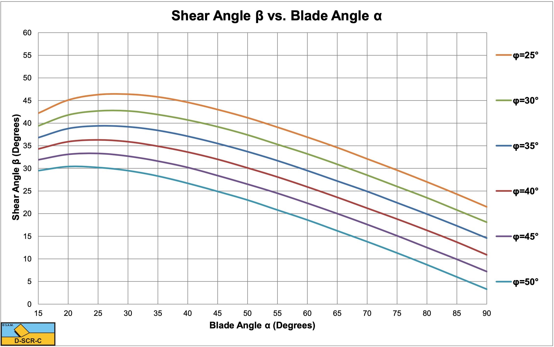
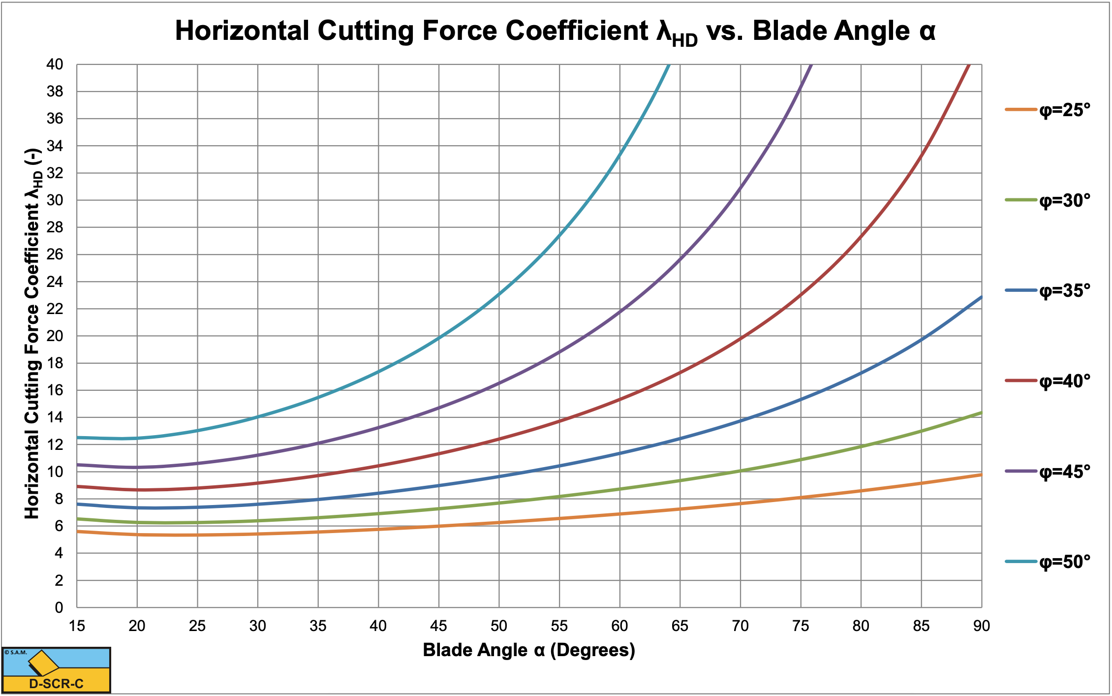
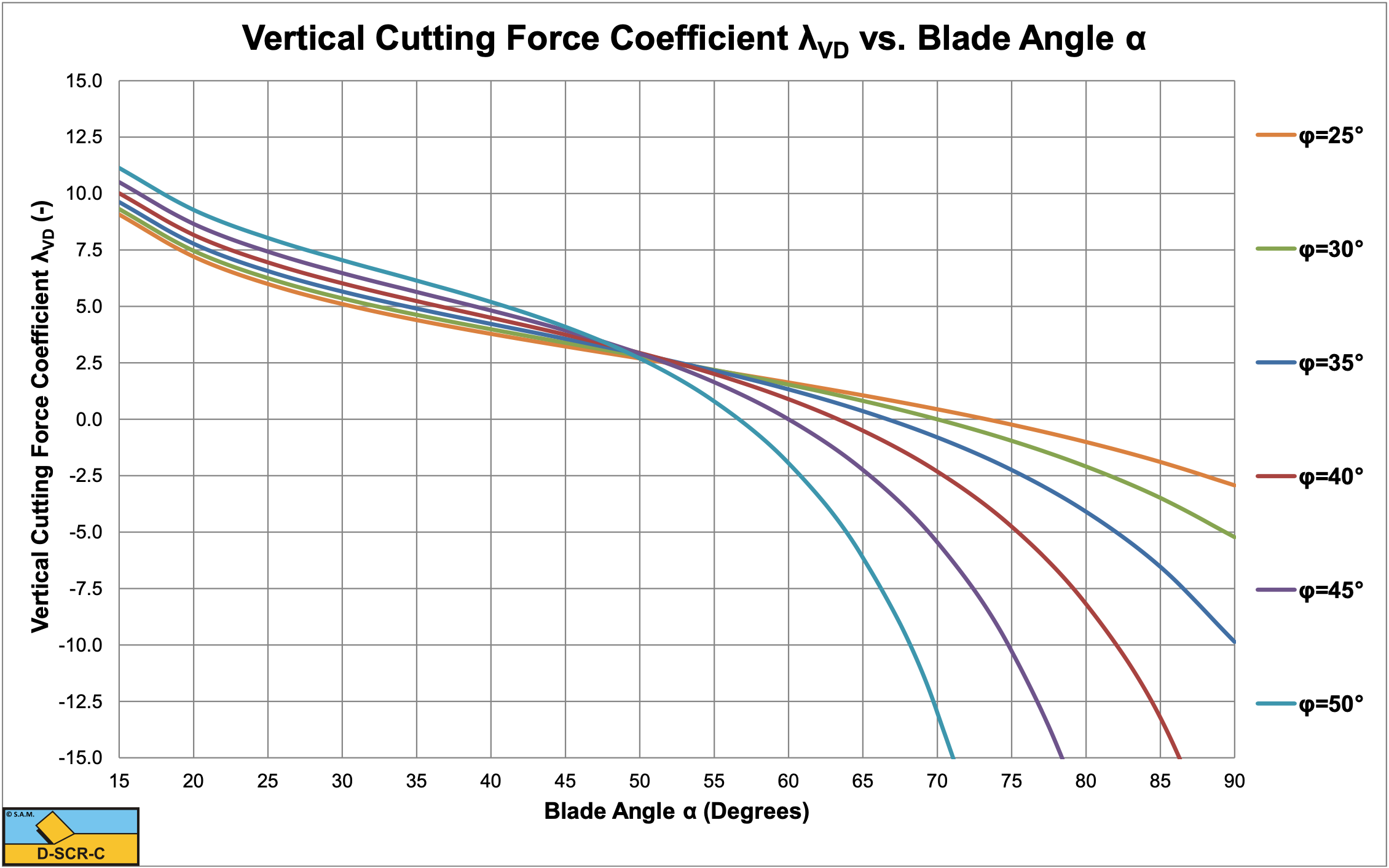
For blade angles up to 60°, there is not much influence of the angle of internal friction on the vertical force. The horizontal force and the shear angle however depend strongly on the angle of internal friction. At large blade angles, the horizontal force becomes very large, while the vertical force changes sign and becomes very large negative (upwards directed). The shear angle decreases with increasing blade angle and angle of internal friction.
At large blade angles nature will look for an alternative mechanism, the wedge mechanism, which is discussed in later chapters.