
5.4: An Alternative Shape of the Layer Cut
- Page ID
- 29446

The shape of the layer cut will most probably be different with dry sand cutting compared to saturated sand cutting or clay and rock cutting. First of all with dry sand cutting the cutting forces are determined by the weight of the layer cut while with the other types of soil the weight can be neglected. Secondly in dry sand there are no forces to keep the layer cut together, so the sand will move down if possible and the maximum slopes will be under the angle of natural repose φnr (usually about 30°). Figure 5-9 shows this alternative shape of the layer cut. The line D-E-F is the top of the sand, where the two marked areas have the same cross section.
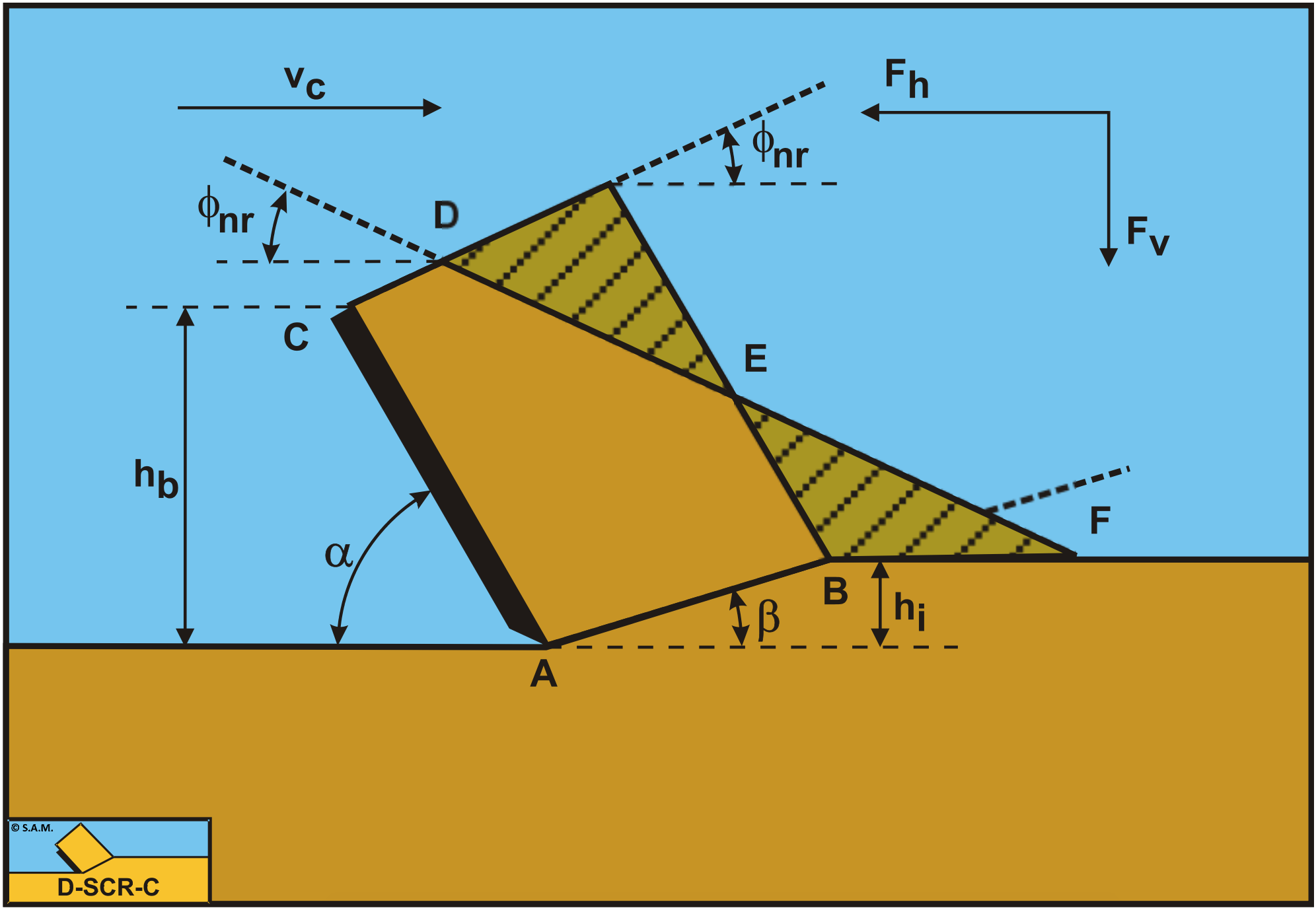
The gravitational force (weight dry) follows, based on Figure 5-9, from:
\[\ \mathrm{G}= \rho_{\mathrm{s}} \cdot \mathrm{g} \cdot \mathrm{h}_{\mathrm{i}} \cdot \mathrm{w} \cdot \frac{\sin (\boldsymbol{\alpha}+\boldsymbol{\beta})}{\sin (\beta)} \cdot\left\{\frac{\mathrm{h}_{\mathrm{b}}}{\sin (\alpha)}+\frac{\mathrm{h}_{\mathrm{i}} \cdot \cos (\alpha+\beta)}{2 \cdot \sin (\beta)}-\frac{\mathrm{h}_{\mathrm{i}} \cdot \sin (\alpha+\beta)}{2 \cdot \sin (\beta)} \cdot \frac{\cos \left(\alpha+\varphi_{\mathrm{n r}}\right)}{\sin \left(\alpha+\varphi_{\mathrm{n r}}\right)}\right\} \tag{5-15}\]
Based on the weight only of the soil, the forces can now be expressed as:
\[\ \begin{array}{left} \mathrm{F}_{\mathrm{h}}=\rho_{\mathrm{s}} \cdot \mathrm{g} \cdot \mathrm{h}_{\mathrm{i}}^{\mathrm{2}} \cdot \mathrm{w} \cdot \lambda_{\mathrm{H} \mathrm{D}}\\
\text{With :} \quad \lambda_{\mathrm{H D}}=\frac{\sin (\alpha+\beta)}{\sin (\beta)} \cdot \frac{\sin (\beta+\varphi) \cdot \sin (\alpha+\delta)}{\sin (\alpha+\beta+\delta+\varphi)}
\cdot\left\{\frac{h_{\mathrm{b}} / h_{\mathrm{i}}}{\sin (\alpha)}+\frac{\cos (\alpha+\beta)}{2 \cdot \sin (\beta)}-\frac{\sin (\alpha+\beta)}{2 \cdot \sin (\beta)} \cdot \frac{\cos \left(\alpha+\varphi_{\mathrm{nr}}\right)}{\sin \left(\alpha+\varphi_{\mathrm{nr}}\right)}\right\}\end{array}\tag{5-16}\]
\[\ \begin{array}{left}\mathrm{F}_{\mathrm{v}}=\rho_{\mathrm{s}} \cdot \mathrm{g} \cdot \mathrm{h}_{\mathrm{i}}^{2} \cdot \mathrm{w} \cdot \lambda_{\mathrm{V D}}\\
\text{With : }\quad \lambda_{\mathrm{V D}}=\frac{\sin (\alpha+\beta)}{\sin (\beta)} \cdot \frac{\sin (\beta+\varphi) \cdot \cos (\alpha+\delta)}{\sin (\alpha+\beta+\delta+\varphi)}
\cdot\left\{\frac{\mathrm{h}_{\mathrm{b}} / \mathrm{h}_{\mathrm{i}}}{\sin (\alpha)}+\frac{\cos (\alpha+\beta)}{2 \cdot \sin (\beta)}-\frac{\sin (\alpha+\beta)}{2 \cdot \sin (\beta)} \cdot \frac{\cos \left(\alpha+\varphi_{\mathrm{nr}}\right)}{\sin \left(\alpha+\varphi_{\mathrm{nr}}\right)}\right\}\end{array}\tag{5-17}\]
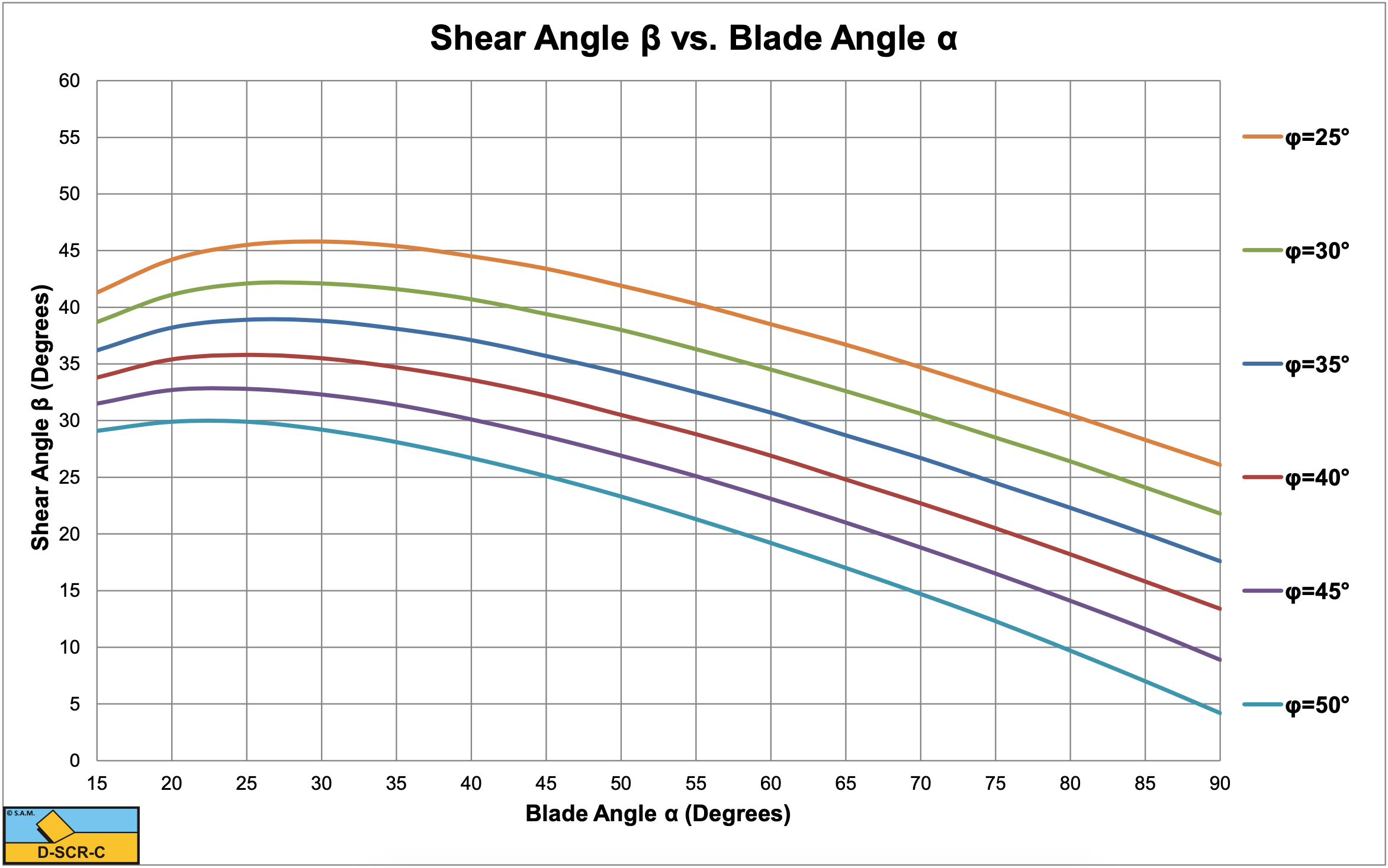
Figure 5-10, Figure 5-11 and Figure 5-12 show the shear angle and the cutting force coefficients for the alternative shape of the layer cut. The difference with the standard configuration is small. Other configurations may exist, but no big differences are expected. The model for dry sand or gravel can also be used for saturated sand, if the cutting process is completely drained and there are no pore vacuum pressures. This only occurs if the permeability is very high, which could be the case in gravel. Of course the dry density of the sand or gravel has to be replaced by the submerged density of the sand or gravel, which is usually close to unity.
The shapes of the curves between the standard configuration and the alternative configuration are very similar. The shear angle first increases with an increasing blade angle up to a maximum after which the shear angle decreases with a further increasing shear angle. The shear angle also decreases with an increasing angle of internal friction. It should be noted here that the external friction angle is assumed to be 2/3 of the internal friction angle.
The cutting forces become very high at large blade angles (close to 90°). Nature will find an alternative cutting mechanism in this case which has been identified as the wedge mechanism. At which blade angle the wedge mechanism will start to occur depends on the internal and external friction angles, but up to a blade angle of 60° the model as described here can be applied. See Chapter 11: A Wedge in Dry Sand Cutting. for detailed information on the wedge mechanism.