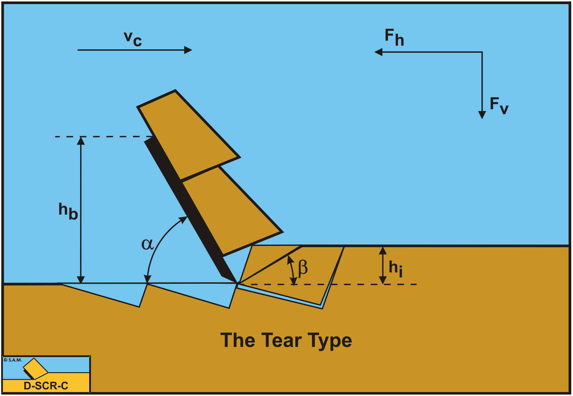
7.5: The Tear Type
- Page ID
- 29461

7.5.1. Introduction
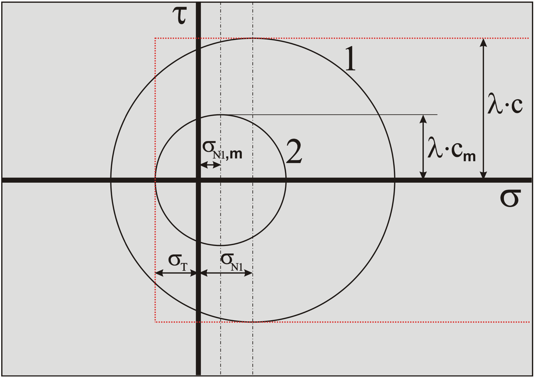
In the previous chapter, the equations for the cutting forces of the Flow Type cutting mechanism have been derived. These equation however do not take into consideration that normal forces and thus stresses may become negative and may exceed the tensile strength of the clay. If the tensile stresses exceed the tensile strength, tensile failure will occur and the clay will not fail by plastic shear failure, but by tensile failure. The failure mechanism in this case is named the Tear Type mechanism. Based on the Mohr circle, tensile cracks will occur under and angle of 45 degrees downwards with respect of the shear angle as is shown in Figure 7-26. When the blade is progressing with the cutting velocity, after a short while a so called secondary crack will occur under 90 degrees with the first (primary) crack. The model as derived in this chapter, does not assume that the tensile strength is exceeded at the moment of tensile crack forming over the full length of the tensile crack. The model assumes that the tensile strength is exceeded at the start of the tensile crack only. In order to determine whether the tensile strength is exceeded, the average shear stress in the shear plane is used. Of course there may be a stress distribution in the shear plane, leading to locally higher and lower shear stresses and thus normal stresses, but these cannot be determined with the methodology used. Only average stresses can be determined. The methodology applied however gives reasonable and practical tools to determine whether the Tear Type cutting mechanism will occur or not.
7.5.2. The Normal Force on the Shear Plane
In order to determine the normal (possibly tensile) stresses on the shear plane, first the normal force on the shear plane has to be determined.
\[\ \mathrm{N}_{1}=\frac{-\mathrm{C} \cdot \cos (\alpha+\beta)+\mathrm{A}}{\sin (\alpha+\beta)}\tag{7-63}\]
Substituting the equations for the cohesive force C and the adhesive force A gives:
\[\ \mathrm{N}_{1}=\frac{-\frac{\lambda_{\mathrm{s}} \cdot \mathrm{c} \cdot \mathrm{h}_{\mathrm{i}} \cdot \mathrm{w}}{\sin (\beta)} \cdot \cos (\alpha+\beta)+\frac{\lambda_{\mathrm{s}} \cdot \mathrm{a} \cdot \mathrm{h}_{\mathrm{b}} \cdot \mathrm{w}}{\sin (\alpha)}}{\sin (\alpha+\beta)}\tag{7-64}\]
The average normal stress on the shear plane equals the normal force on the shear plane N1, divided by the cross sectional area of the shear plane, giving:
\[\ \sigma_{\mathrm{N} 1}=\frac{\mathrm{N}_{1} \cdot \sin (\beta)}{\mathrm{h}_{\mathrm{i}} \cdot \mathrm{w}}\tag{7-65}\]
Substituting equation (7-64) in equation (7-65) gives for the normal stress on the shear plane:
\[\ \begin{array}{left} \sigma_{\mathrm{N} 1}&= \frac{\sin (\beta)}{\mathrm{h}_{\mathrm{i}} \cdot \mathrm{w}} \cdot \frac{-\frac{\lambda_{\mathrm{s}} \cdot \mathrm{c} \cdot \mathrm{h}_{\mathrm{i}} \cdot \mathrm{w}}{\sin (\beta)} \cdot \cos (\alpha+\beta)+\frac{\lambda_{\mathrm{s}} \cdot \mathrm{a} \cdot \mathrm{h}_{\mathrm{b}} \cdot \mathrm{w}}{\sin (\alpha)}}{\sin (\alpha+\beta)} \\ &=\lambda_{\mathrm{s}} \cdot \mathrm{c} \cdot \frac{-\cos (\alpha+\beta)+r \cdot \frac{\sin (\beta)}{\sin (\alpha)}}{\sin (\alpha+\beta)} \end{array}\tag{7-66}\]
Assuming a fixed strain rate factor λs for cohesion and tensile strength, the normal stress minus the shear strength (cohesion) has to be bigger than the tensile strength, where the tensile strength is negative (compressive stresses are positive).
\[\ \sigma_{\mathrm{N} 1}-\lambda_{\mathrm{s}} \cdot \mathrm{c} \geq \lambda_{\mathrm{s}} \cdot \sigma_{\mathrm{T}}\tag{7-67}\]
Substituting equation (7-66) into equation (7-67) gives the condition for ductile failure:
\[\ \lambda_{\mathrm{s}} \cdot \mathrm{c} \cdot \frac{-\cos (\alpha+\beta)+r \cdot \frac{\sin (\beta)}{\sin (\alpha)}}{\sin (\alpha+\beta)}-\lambda_{\mathrm{s}} \cdot \mathrm{c} \geq \lambda_{\mathrm{s}} \cdot \sigma_{\mathrm{T}}\tag{7-68}\]
The transition from the Flow Type mechanism to the Tear Type mechanism is at the moment where the equal sign is used in the above equation, resulting in a critical ratio between the tensile strength and the shear strength, still also depending on the ac ratio r according to:
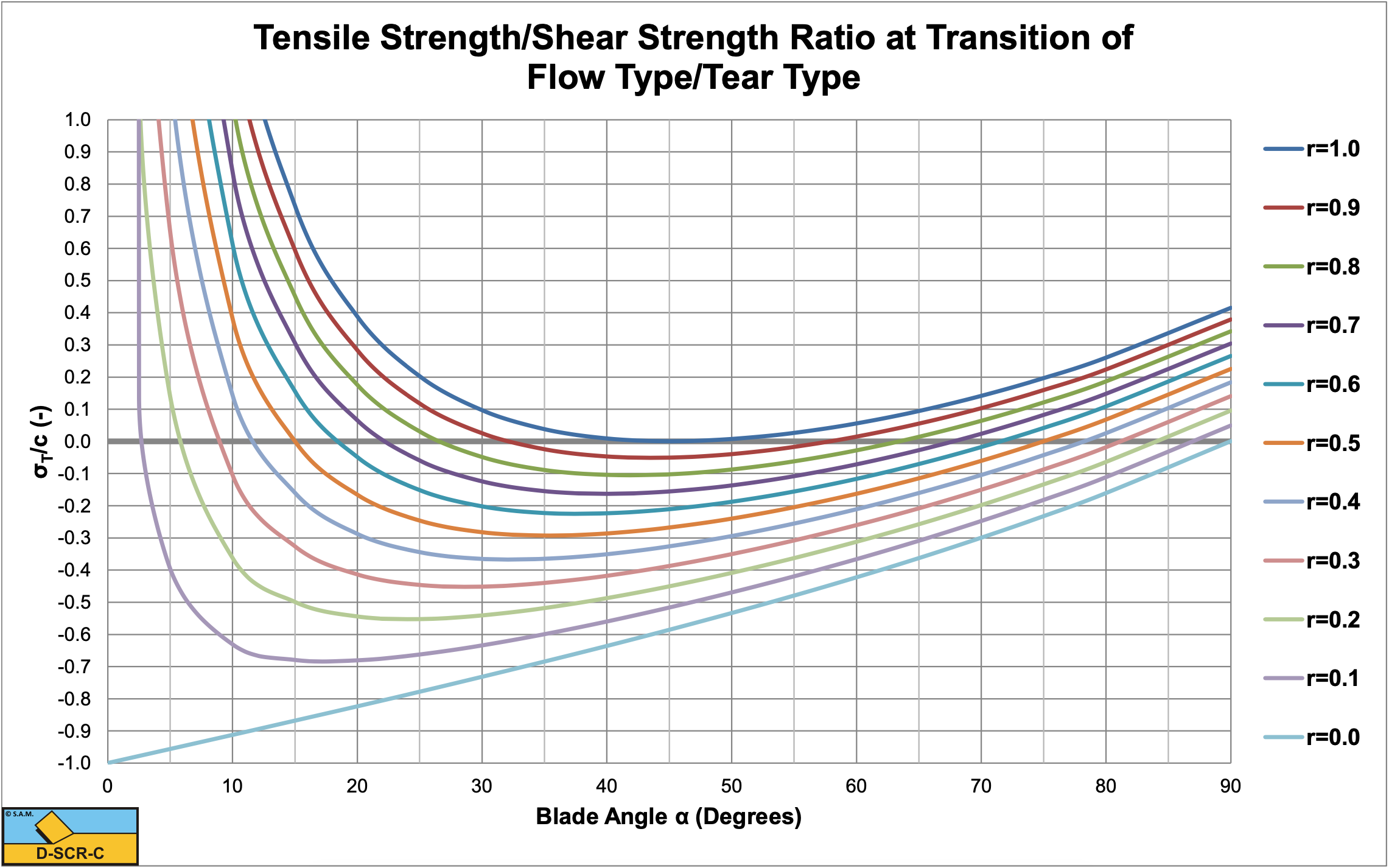
\[\ \mathrm{\frac{\sigma_{T}}{c}}=\mathrm{\left(\frac{r \cdot \frac{\sin (\beta)}{\sin (\alpha)}-\cos (\alpha+\beta)-\sin (\alpha+\beta)}{\sin (\alpha+\beta)}\right)}\tag{7-69}\]
Figure 7-27 shows the critical ratio curves of the ratio of the tensile strength to the shear strength (cohesion) of the transition of the Flow Type mechanism to the Tear Type mechanism. Since the tensile strength is considered to be negative, the more negative this ratio, the higher the relative tensile strength. Below a curve the Flow Type may be expected, above a curve the Tear Type. Only negative ratios should be considered, since the tensile strength cannot be positive. The figure shows that for r=1 (high adhesive forces) the curve just touches a ratio of zero, but never becomes negative, meaning the Tear Type will never occur. For smaller r values the curves are more negative for a decreasing r value. The minimum for r is zero (no adhesion). The figure also shows that all curves (except the r=0 curve) start with a positive value, then decrease with an increasing blade angle to a minimum value and with a further increasing blade angle increase again to positive values. For blade angles larger than 90 degrees tensile failure will never occur. Because of the choice of the parameter hb, the blade height, at constant blade height the length of the blade is increasing with a decreasing blade angle. This means that the adhesive force on the blade increases with a decreasing blade angle, resulting in increasing normal stresses on the shear plane. Higher normal stresses suppress tensile failure. On the other hand, an increasing blade angle will increase the normal stress on the shear plane because of the force equilibrium. So we have two effects, the normal stresses on the shear plane will decrease with an increasing blade angle because of the decrease of the adhesive force and the normal stresses will increase with an increases blade angle because of the force equilibrium. The result is a curve with a minimum.
7.5.3. The Mobilized Shear Strength
Assuming a mobilized shear stress cm in the shear plane at the moment of tensile failure, gives:
\[\ \mathrm{c_{m} \cdot\left(\frac{r_{m} \cdot \frac{\sin (\beta)}{\sin (\alpha)}-\cos (\alpha+\beta)-\sin (\alpha+\beta)}{\sin (\alpha+\beta)}\right)=\sigma_{T}}\tag{7-70}\]
Or:
\[\ \mathrm{c}_{\mathrm{m}}=\sigma_{\mathrm{T}} \cdot\left(\frac{\sin (\alpha+\beta)}{\mathrm{r}_{\mathrm{m}} \cdot \frac{\sin (\beta)}{\sin (\alpha)}-\cos (\alpha+\beta)-\sin (\alpha+\beta)}\right)\tag{7-71}\]
Since the mobilized shear stress cm is smaller than the shear strength c, also the ac ratio rm will be different from the ac ratio r when the shear stress is fully mobilized up to the shear strength. This gives for the mobilized ac ratio rm:
\[\ \mathrm{r}_{\mathrm{m}}=\frac{\mathrm{a} \cdot \mathrm{h}_{\mathrm{b}}}{\mathrm{c}_{\mathrm{m}} \cdot \mathrm{h}_{\mathrm{i}}}=\frac{\mathrm{a} \cdot \mathrm{h}_{\mathrm{b}}}{\sigma_{\mathrm{T}} \cdot \mathrm{h}_{\mathrm{i}}} \cdot\left(\frac{\mathrm{r}_{\mathrm{m}} \cdot \frac{\sin (\beta)}{\sin (\alpha)}-\cos (\alpha+\beta)-\sin (\alpha+\beta)}{\sin (\alpha+\beta)}\right)\tag{7-72}\]
The mobilized ac ratio rm is present on both sides of the equal sign. This gives for the mobilized ac ratio rm:
\[\ \begin{array}{left}\mathrm{r}_{\mathrm{m}}=\frac{\mathrm{r}_{\mathrm{T}} \cdot\left(\mathrm{1}+\frac{\cos (\alpha+\beta)}{\sin (\alpha+\beta)}\right)}{\left(\mathrm{r}_{\mathrm{T}} \cdot \frac{\sin (\beta)}{\sin (\alpha) \cdot \sin (\alpha+\beta)}-1\right)}\\
\text{With: } \mathrm{r_T}=\mathrm{\frac{a\cdot h_b}{\sigma_t\cdot h_i}}\end{array}\tag{7-73}\]
The normal stress on the shear plane is now:
\[\ \sigma_{\mathrm{N} 1, \mathrm{m}}=\lambda_{\mathrm{s}} \cdot \mathrm{c}_{\mathrm{m}} \cdot \frac{-\cos (\alpha+\beta)+\mathrm{r}_{\mathrm{m}} \cdot \frac{\sin (\beta)}{\sin (\alpha)}}{\sin (\alpha+\beta)}\tag{7-74}\]
7.5.4. The Resulting Cutting Forces
Substituting the mobilized shear strength cm and the mobilized ac ratio rm gives the horizontal and vertical forces in the case of brittle failure, the Tear Type cutting mechanism:
\[\ \begin{array}{left} \mathrm{F_{\mathrm{h}}}&=\mathrm{\lambda_{\mathrm{s}} \cdot \sigma_{\mathrm{T}} \cdot \mathrm{h}_{\mathrm{i}} \cdot \mathrm{w} \cdot \frac{\frac{\sin (\alpha)}{\sin (\beta)}+r_{\mathrm{m}} \cdot \frac{\sin (\beta)}{\sin (\alpha)}}{r_{\mathrm{m}} \cdot \frac{\sin (\beta)}{\sin (\alpha)}-\cos (\alpha+\beta)-\sin (\alpha+\beta)}}\\
&=\lambda_{\mathrm{s}} \cdot \sigma_{\mathrm{T}} \cdot \mathrm{h}_{\mathrm{i}} \cdot \mathrm{w} \cdot \mathrm{r}_{\mathrm{T}} \cdot \frac{\lambda_{\mathrm{HT}}}{\mathrm{r}_{\mathrm{T}}}\end{array}\tag{7-75}\]
\[\ \begin{array}{left}\mathrm{F}_{\mathrm{v}}&=\lambda_{\mathrm{s}} \cdot \sigma_{\mathrm{T}} \cdot \mathrm{h}_{\mathrm{i}} \cdot \mathrm{w} \cdot \frac{\frac{\cos (\alpha)}{\sin (\beta)}-\mathrm{r}_{\mathrm{m}} \cdot \frac{\cos (\beta)}{\sin (\alpha)}}{\mathrm{r}_{\mathrm{m}} \cdot \frac{\sin (\beta)}{\sin (\alpha)}-\cos (\alpha+\beta)-\sin (\alpha+\beta)}\\
&=\lambda_{\mathrm{s}} \cdot \sigma_{\mathrm{T}} \cdot \mathrm{h}_{\mathrm{i}} \cdot \mathrm{w} \cdot \mathrm{r}_{\mathrm{T}} \cdot \frac{\lambda_{\mathrm{V} T}}{\mathrm{r}_{\mathrm{T}}}\end{array}\tag{7-76}\]
The cutting forces are not dependent on the shear strength anymore, but completely dependent on the tensile strength and the adhesion.
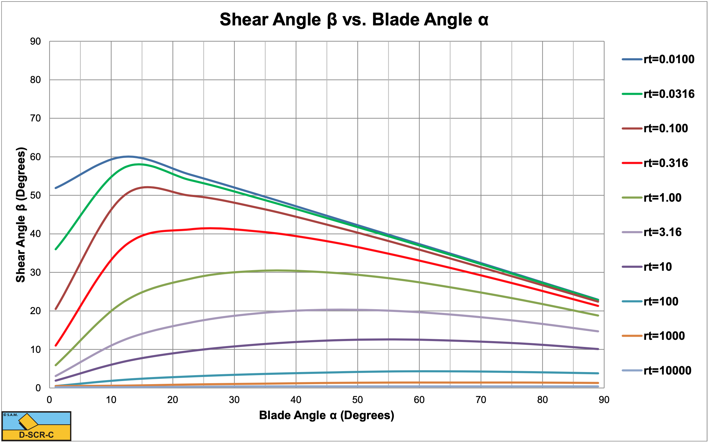
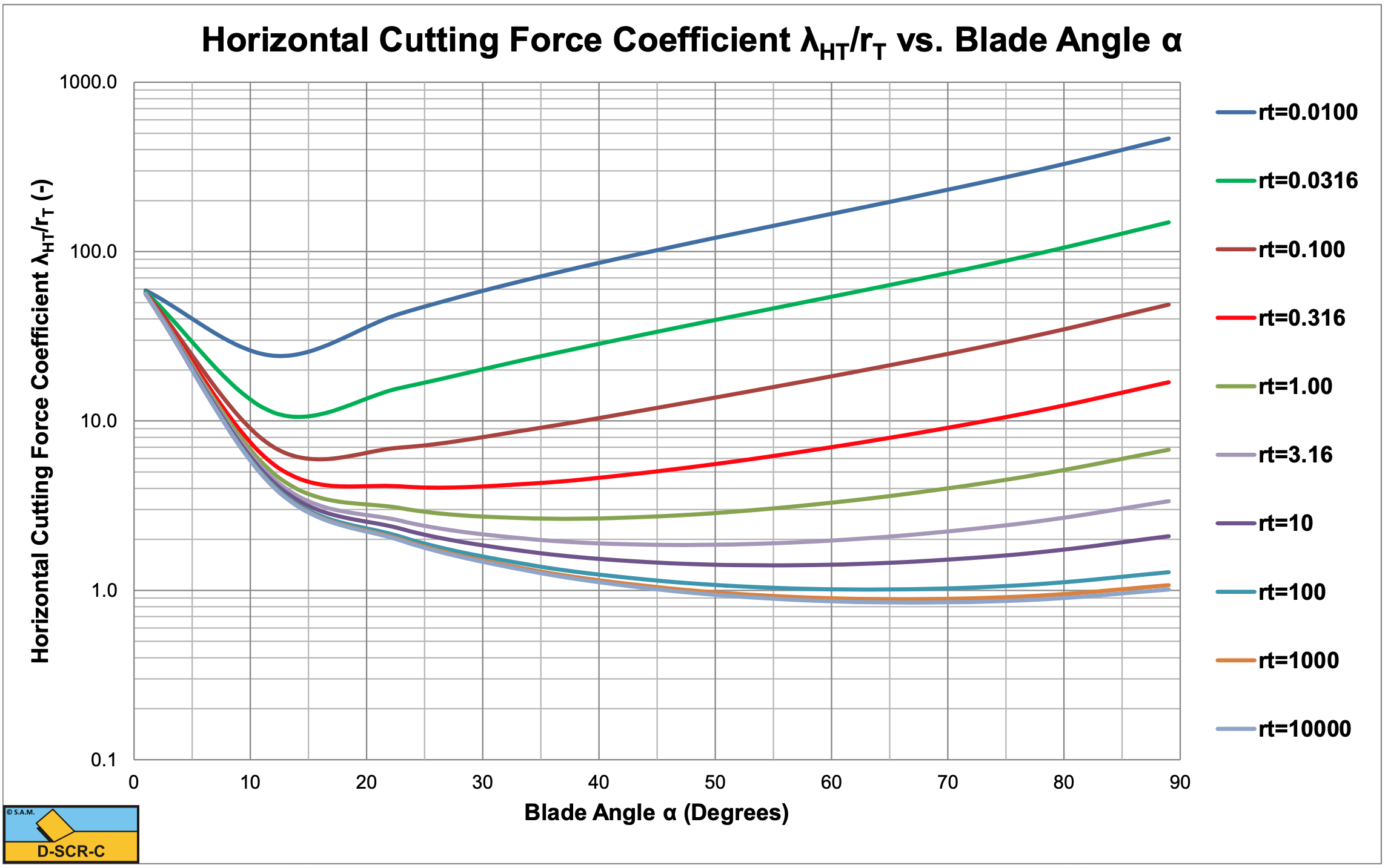
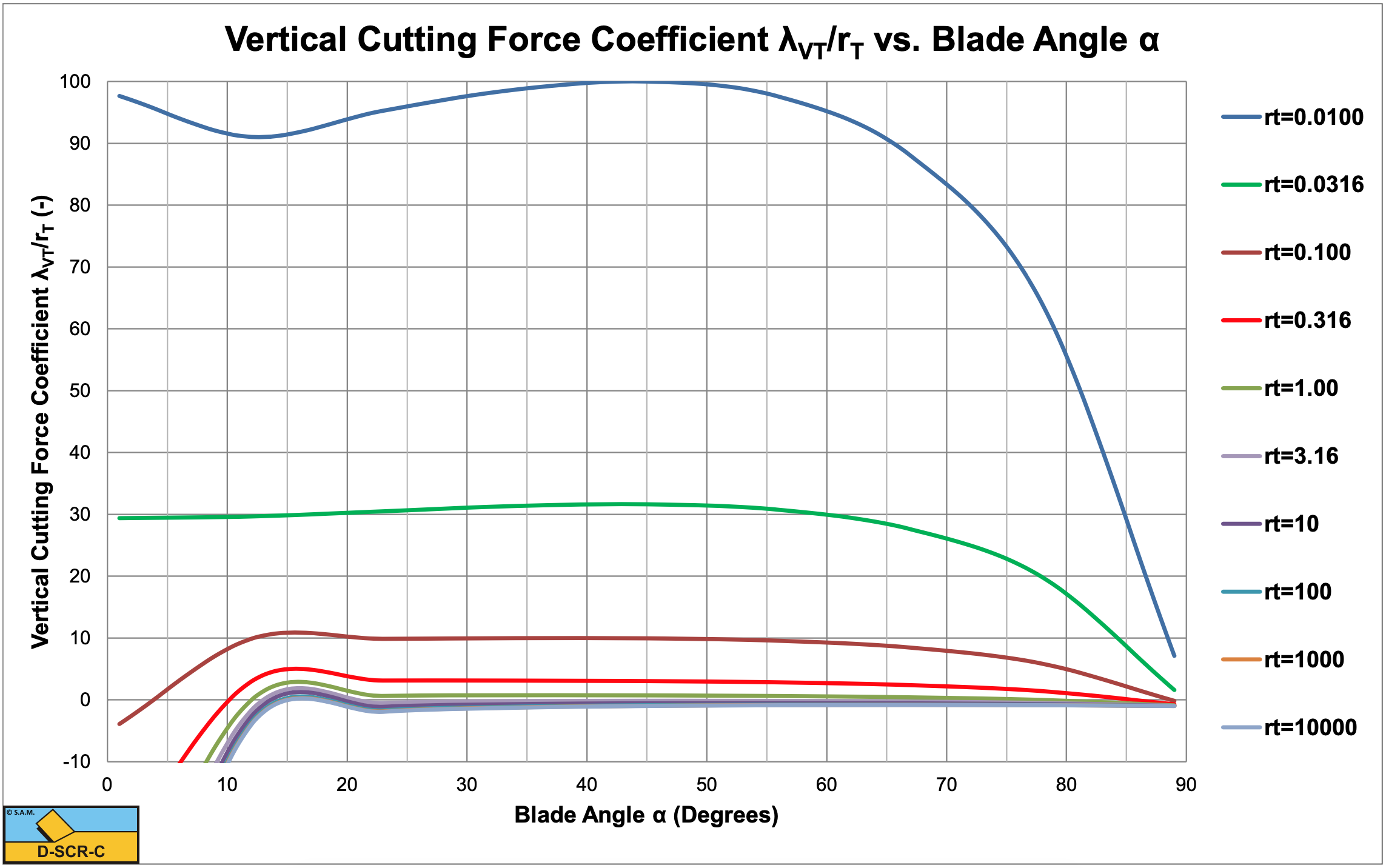
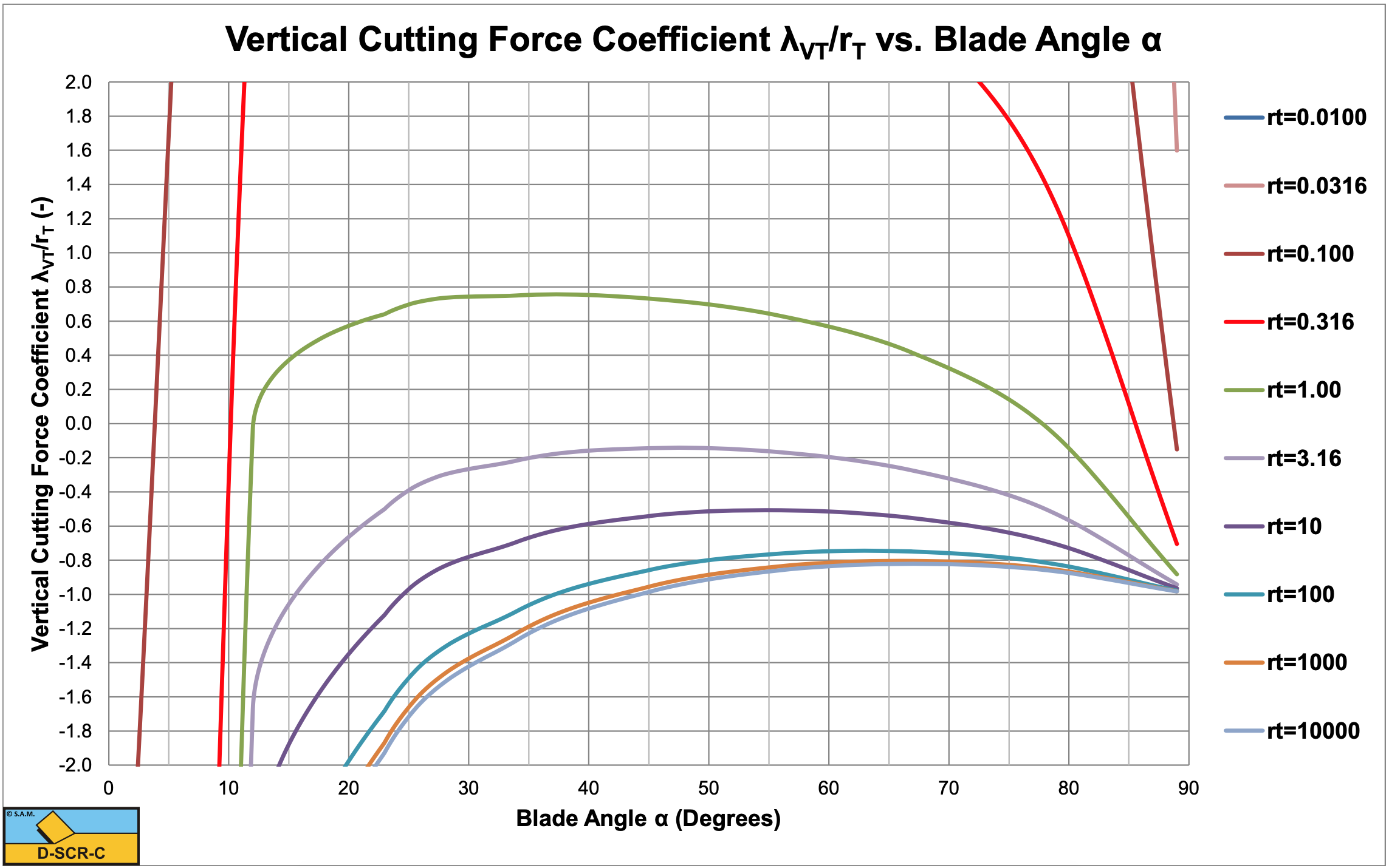
Figure 7-29, Figure 7-30, Figure 7-31 and Figure 7-32 show the shear angle β, the horizontal cutting force coefficient λHT/rT, the vertical cutting force coefficient λVT/rT and the last one zoomed for the Tear Type of cutting mechanism. The figures show that for large values of rT, the shear angle and the cutting force coefficients hardly depend on the factor rT. It should be mentioned that the graphs show λHT/rT and λVT/rT and not λHT and λVT. A large or very large value of rT means a very small tensile strength compared to the adhesion. Equations (8-112) and (8-113) can be rewritten for the case of a very small relative tensile strength according to:
\[\ \begin{array}{left} \mathrm{F}_{\mathrm{h}} &=\lambda_{\mathrm{s}} \cdot \sigma_{\mathrm{T}} \cdot \mathrm{h}_{\mathrm{i}} \cdot \mathrm{w} \cdot \mathrm{r}_{\mathrm{T}} \cdot \frac{\lambda_{\mathrm{H} \mathrm{T}}}{\mathrm{r}_{\mathrm{T}}}=\lambda_{\mathrm{s}} \cdot \sigma_{\mathrm{T}} \cdot \mathrm{h}_{\mathrm{i}} \cdot \mathrm{w} \cdot \frac{\mathrm{a} \cdot \mathrm{h}_{\mathrm{b}}}{\sigma_{\mathrm{T}} \cdot \mathrm{h}_{\mathrm{i}}} \cdot \frac{\lambda_{\mathrm{H} \mathrm{T}}}{\mathrm{r}_{\mathrm{T}}} \\ &=\lambda_{\mathrm{s}} \cdot \mathrm{a} \cdot \mathrm{h}_{\mathrm{b}} \cdot \mathrm{w} \cdot \frac{\lambda_{\mathrm{H T}}}{\mathrm{r}_{\mathrm{T}}} \end{array}\tag{7-77}\]
\[\ \begin{array}{left} \mathrm{F}_{\mathrm{v}} &=\lambda_{\mathrm{s}} \cdot \sigma_{\mathrm{T}} \cdot \mathrm{h}_{\mathrm{i}} \cdot \mathrm{w} \cdot \mathrm{r}_{\mathrm{T}} \cdot \frac{\lambda_{\mathrm{V T}}}{\mathrm{r}_{\mathrm{T}}}=\lambda_{\mathrm{s}} \cdot \sigma_{\mathrm{T}} \cdot \mathrm{h}_{\mathrm{i}} \cdot \mathrm{w} \cdot \frac{\mathrm{a} \cdot \mathrm{h}_{\mathrm{b}}}{\sigma_{\mathrm{T}} \cdot \mathrm{h}_{\mathrm{i}}} \cdot \frac{\lambda_{\mathrm{V T}}}{\mathrm{r}_{\mathrm{T}}} \\ &=\lambda_{\mathrm{s}} \cdot \mathrm{a} \cdot \mathrm{h}_{\mathrm{b}} \cdot \mathrm{w} \cdot \frac{\lambda_{\mathrm{V T}}}{\mathrm{r}_{\mathrm{T}}} \end{array}\tag{7-78}\]