7.7: Resulting Forces
- Page ID
- 34820
Now the question is, when do we have a Flow Type, Curling Type or Tear Type and how does this depend on the different parameters. This is explained by a number of examples.
Example 1: Cohesion c=1 kPa, adhesion a=1 kPa, tensile strength σT=-0.3 kPa, blade height hb=0.1 m, blade angle α=55°, forces per unit width of the blade.
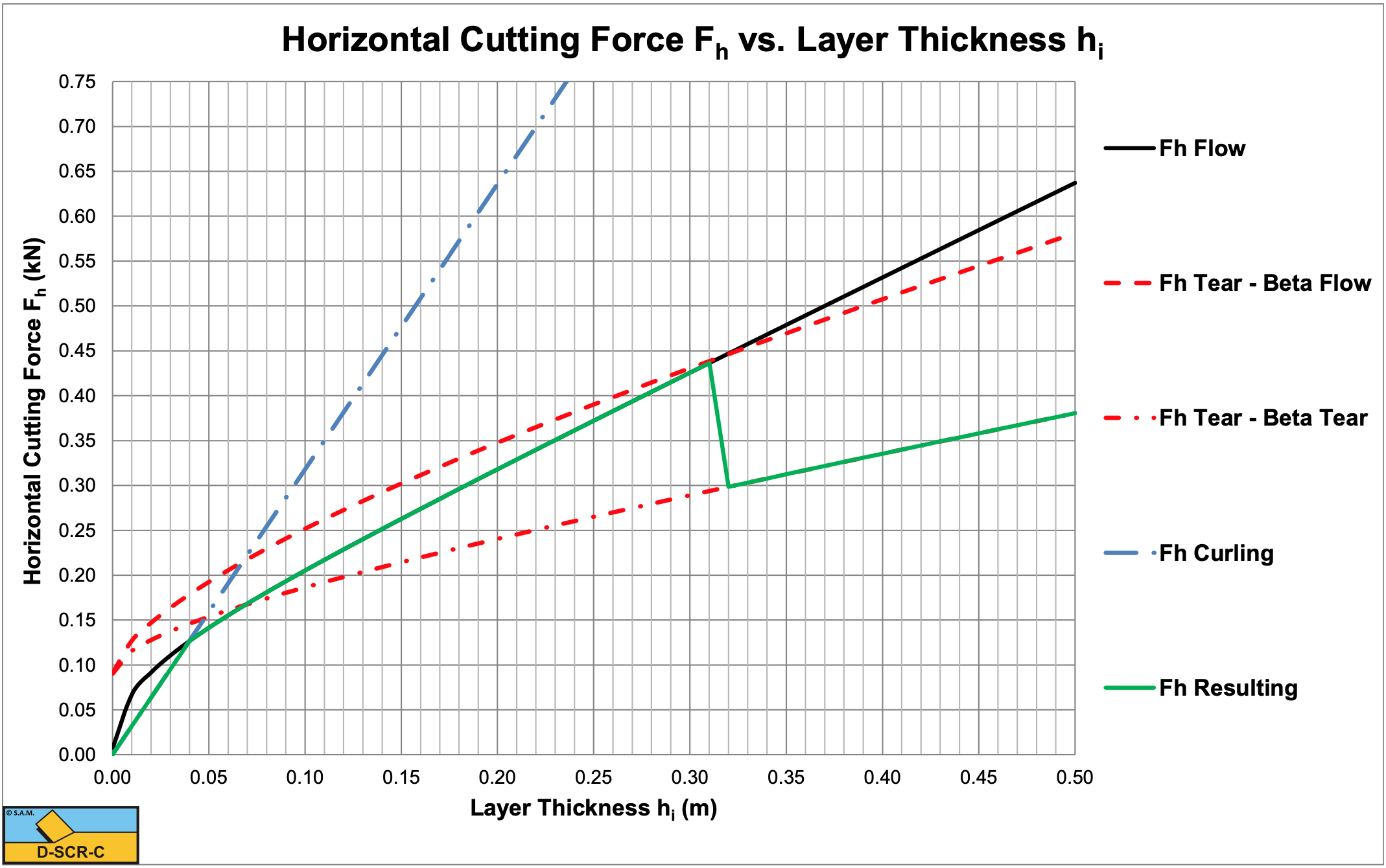
According to Figure 7-27 (see also Figure 7-40) there will be a transition from the Flow Type to the Tear Type at r=0.3, so a layer thickness hi=0.32 m. But will this really happen? Suppose we investigate the undercutting process of a cutter head, where the layer thickness increases from zero to a maximum during the rotation of a blade. When the blade starts cutting the layer thickness is zero and increases in time. First the cutting process is of the Curling Type up to a layer thickness of about hi=0. 65 m. At this layer thickness the mobilized blade height equals the actual blade height and there is a transition from the Curling Type to the Flow Type. When the layer thickness is increased further, at a layer thickness of about hi=0.32 m the normal stresses on the shear plane result in normal stresses more negative than the tensile strength under an angle of 45° downwards with respect to the direction of the shear plane, so there is a transition from the Flow Type to the Tear Type. However, once the Tear Type of cutting mechanism occurs, this mechanism will search for a shear angle, resulting in a minimum cutting force. This shear angle tends not to be equal to the optimum shear angle of the Flow Type. Figure 7-21 shows the optimum shear angle of the Flow Type, while Figure 7-29 shows the optimum shear angle of the Tear Type. The result is a discontinuity in the cutting force, the cutting force is reduced (the beta real curve) at the moment the Tear Type is the cutting mechanism. Another reduction may occur, because the force calculated is the force at the start of a tensile crack. When the blade continues moving forward, the horizontal force will probably be smaller than the force at the initiation of the tensile crack, resulting in a lower average force.
Now suppose we are overcutting with our cutter head. This means we start with some maximum layer thickness thick enough to cause the Tear Type to occur. When the blade progresses, the layer thickness decreases. But since the curve of the real beta is followed, the Tear Type will continue until a layer thickness of about hi=0.065 m is reached. In fact, each time a block of clay breaks out of the clay and the cutting process starts again. At the layer thickness of about hi=0.065 m there is a transition directly from the Tear Type to the Flow Type.

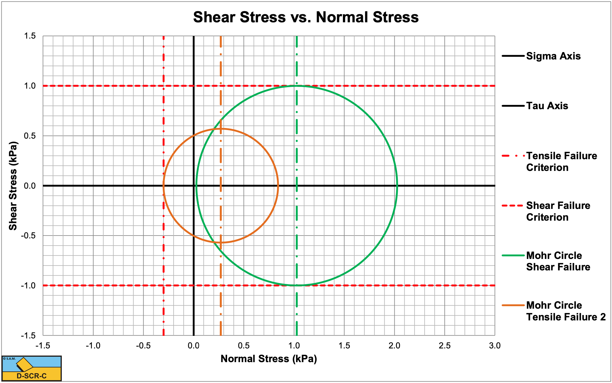
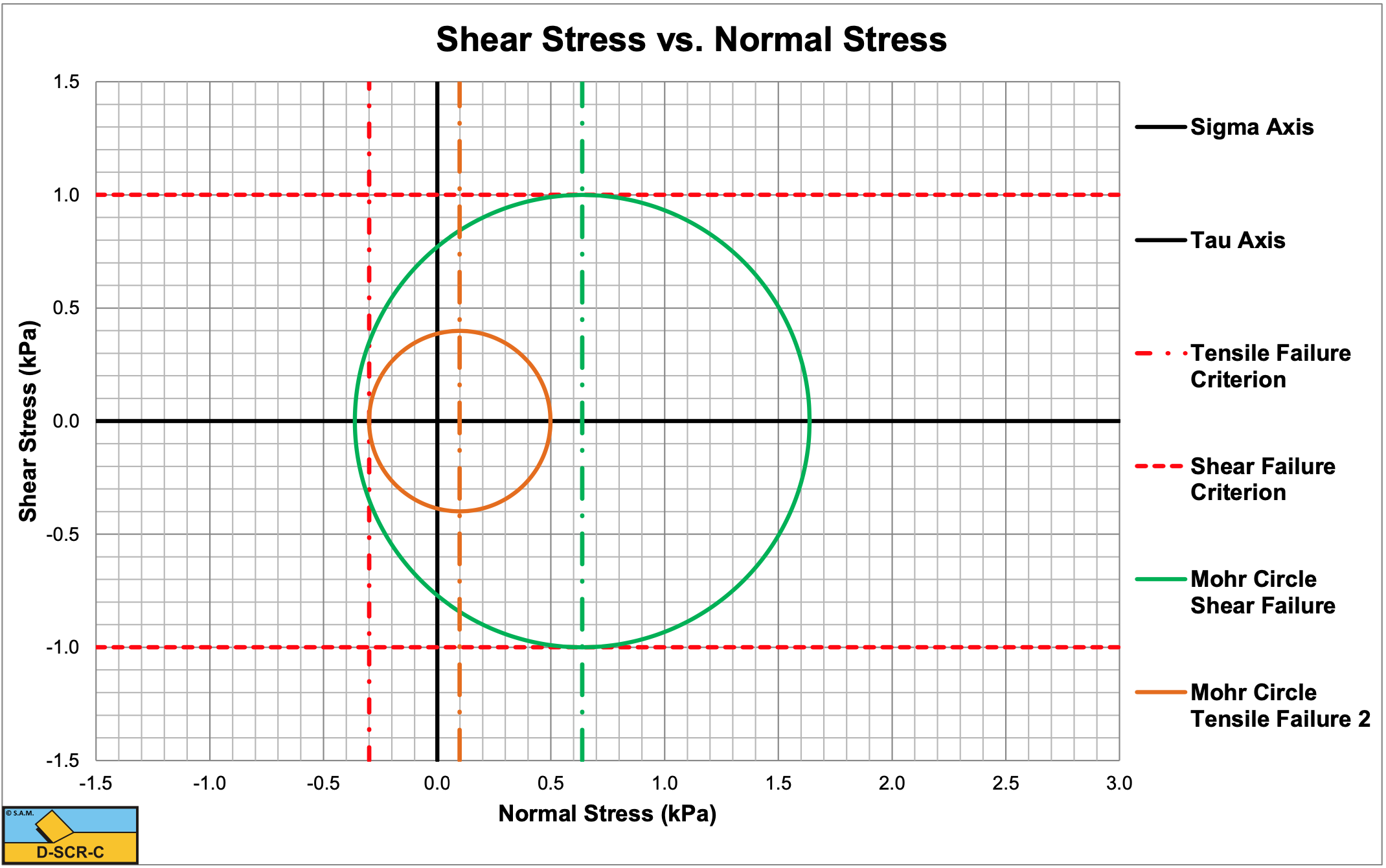
Figure 7-41 shows the Mohr circles for the Flow Type and the Tear Type for a layer thickness of hi=0.1 m. Both mechanisms are possible. Which one occurs depends on the history, since both only touch one failure criterion. Figure 7-42 shows the Mohr circles for the Flow Type and the Tear Type for a layer thickness of hi=0.5 m. The Mohr circle for shear failure (Flow Type) crosses the tensile failure criterion and thus cannot exist. Only one mechanism is possible, the Tear Type.