11.4: Results of some Calculations
- Page ID
- 29355

Since the wedge model depends on many parameters, some example calculations are carried out with the parameters as used by Hatamura & Chijiiwa (1977B). The calculations are carried out with a blade height hb=0.2 m, a blade width w=0.33 m, an angle of internal friction φ=38°, an angle of internal friction δ=2/3·φ, an angle of internal friction on the pseudo blade of λ=32°, a dry density of ρs=1.59 ton/m3 and a cutting velocity of vc=0.05 m/sec. The difference with the Hatamura & Chijiiwa (1977B) experiments is that here the blade height is constant, while in their experiments the blade length was constant. Further layer thicknesses of hi=0.066 m, 0.10 m and 0.20 m are used in the calculations. Based on these and many more calculations an empirical equation has been found for the wedge angle θ.
\[\ \mathrm{\theta=(90-\varphi) \cdot\left(0.73+0.0788 \cdot \frac{h_{\mathrm{b}}}{h_{\mathrm{i}}}\right)}\tag{11-28}\]
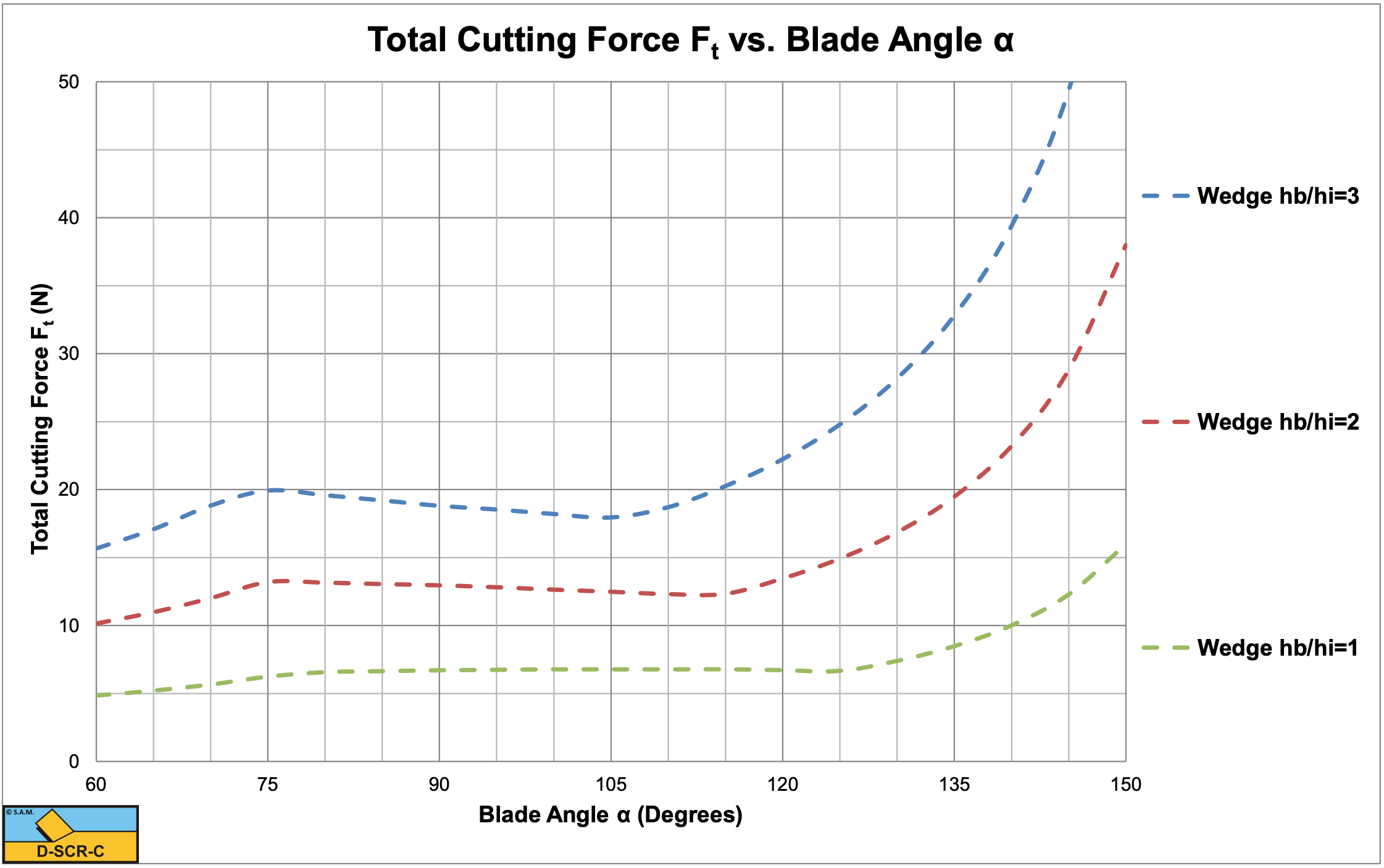
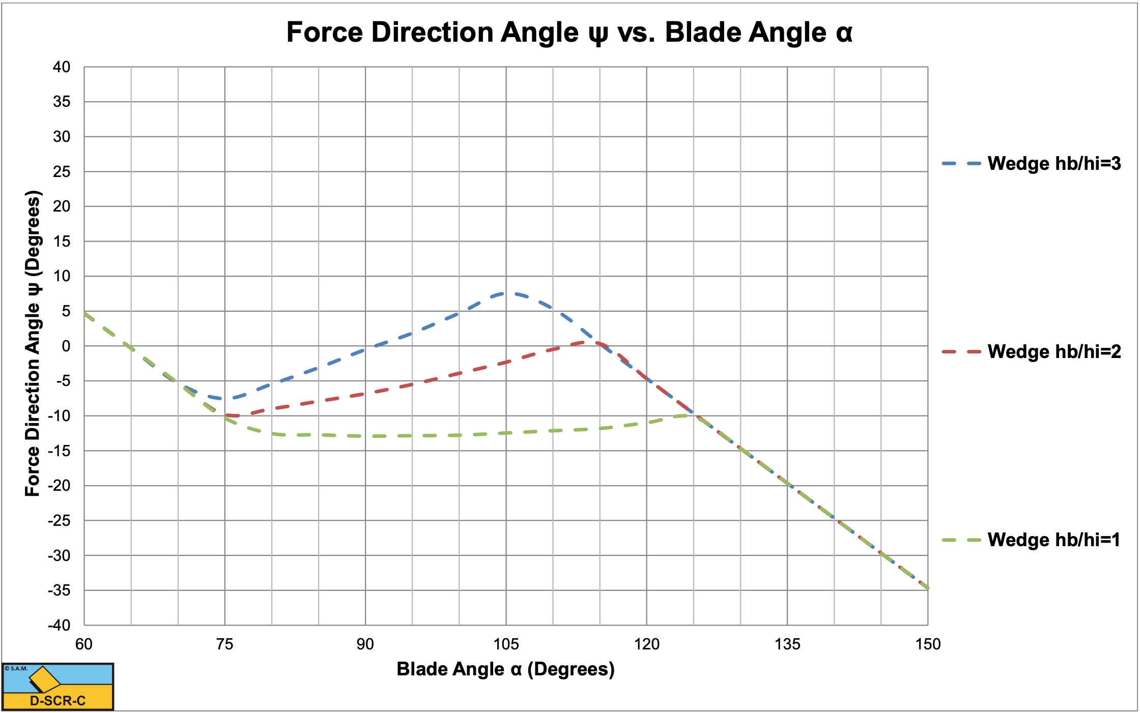
Figure 11-8, Figure 11-9 and Figure 11-10 show the shear angle, the mobilized external friction angle, the wedge angle, the total cutting force and the direction of the total cutting force.
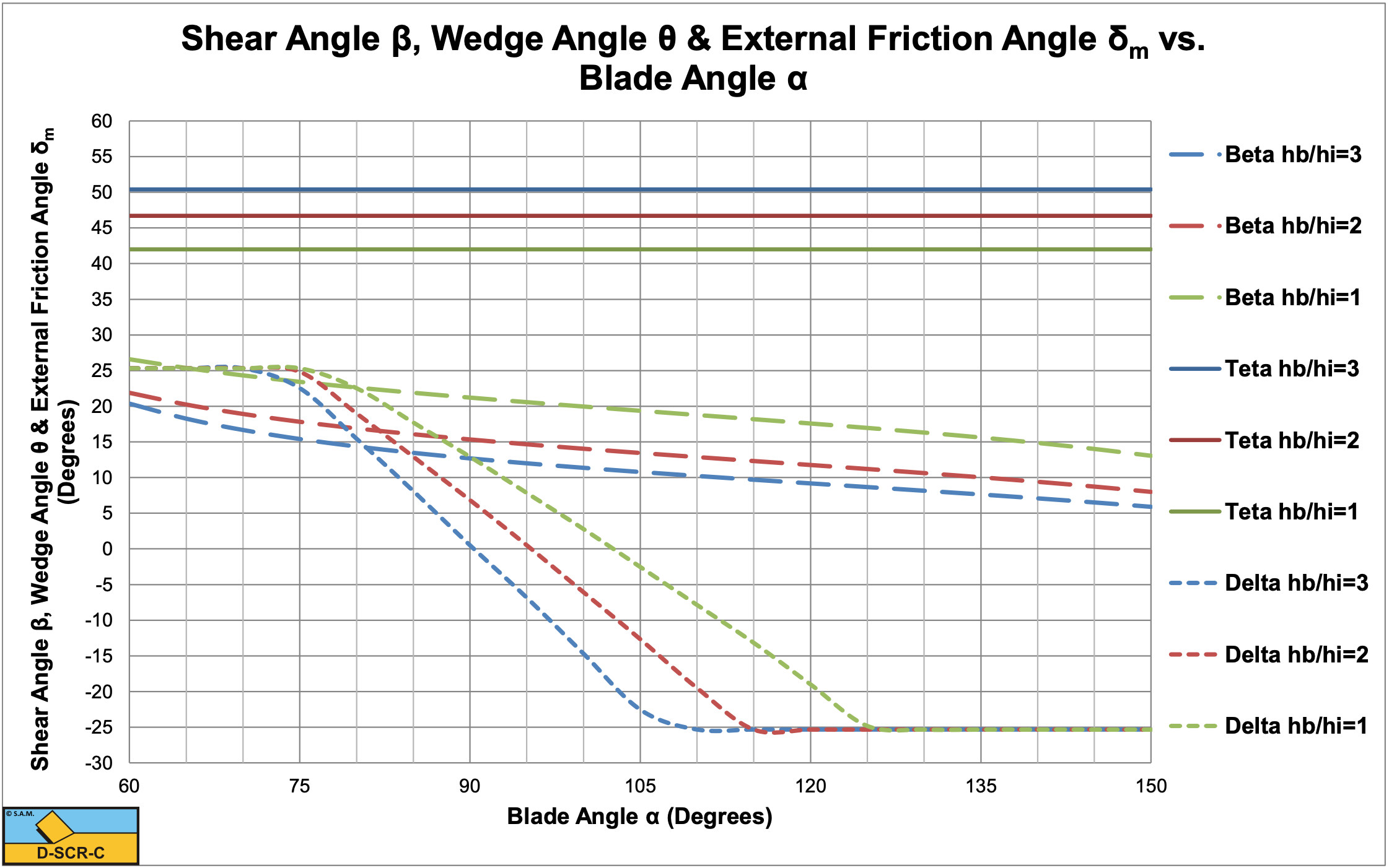
In the region where the mobilized external friction angle changes from plus the maximum to minus the maximum value, an equilibrium of moments exists. In the case considered this means that a wedge may exist in this region. When the mobilized external friction angle equals minus the maximum value there is no equilibrium of moments. In this region the total cutting force increases rapidly with an increasing blade angle in the calculations, but most probably another mechanism than the wedge mechanism will occur, so the values of the cutting forces in that region are not reliable. In the region of the mobilized external friction angle between plus the maximum to minus the maximum value the total cutting force is almost constant.