
17.13: Appendix M- Experiments in Water Saturated Sand
- Page ID
- 35286
M.1 Pore pressures and cutting forces in 105 μm Sand
The cutting forces on the blade. Experiments in 105 μm sand, with α=30°, β=30o, φ=41o, δ=27o, ni=43.6%, nmax=51.6%, ki=0.000062 m/s, kmax=0.000170 m/s, hi=100 mm, hb=100 mm, w=0.2 m, z=0.6 m and a partial cavitating cutting process.
The cutting forces on the blade. Experiments in 105 μm sand, with α=45°, β=30o, φ=38o, δ=25o, ni=45.0%, nmax=51.6%, ki=0.000075 m/s, kmax=0.000170 m/s, hi=70 mm, hb=100 mm, w=0.2 m, z=0.6 m and a partial cavitating cutting process.
The cutting forces on the blade. Experiments in 105 μm sand, with α=60°, β=30o, φ=36o, δ=24o, ni=44.3%, nmax=51.6%, ki=0.000067 m/s, kmax=0.000170 m/s, hi=58 mm, hb=100 mm, w=0.2 m, z=0.6 m and a partial cavitating cutting process.
M.2 Pore Pressures in 200 μm Sand
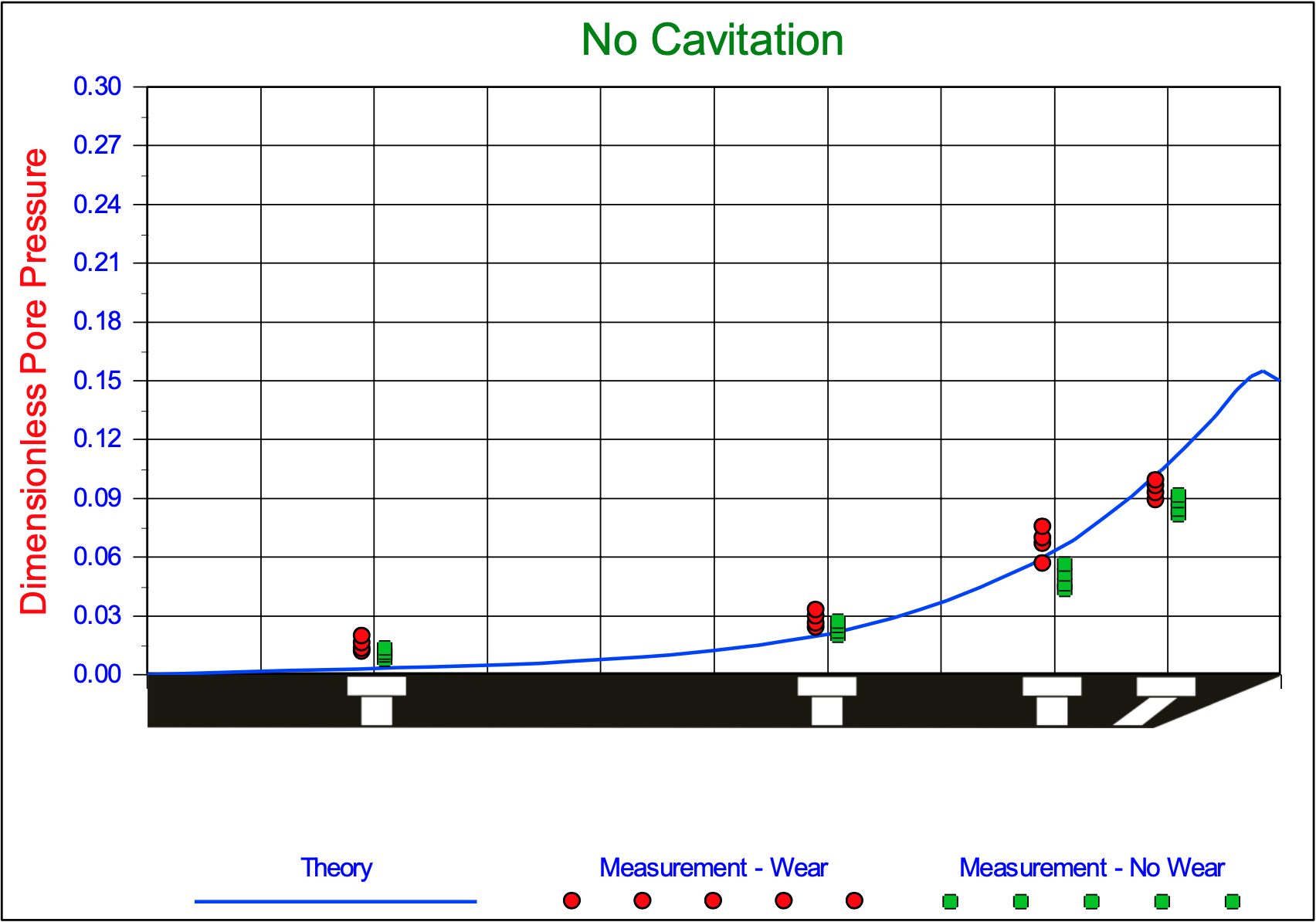
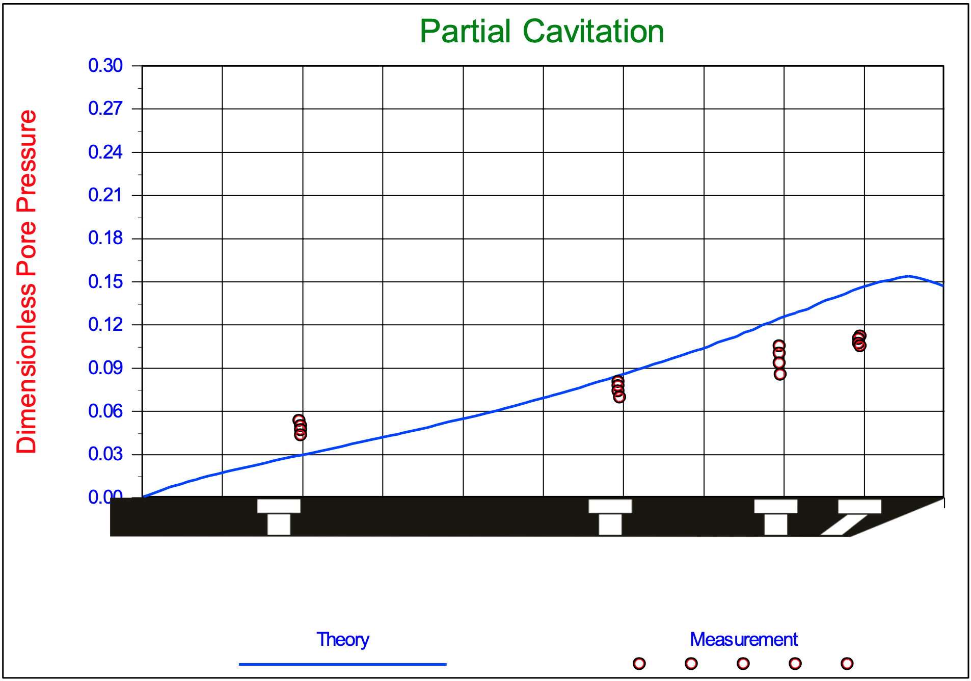
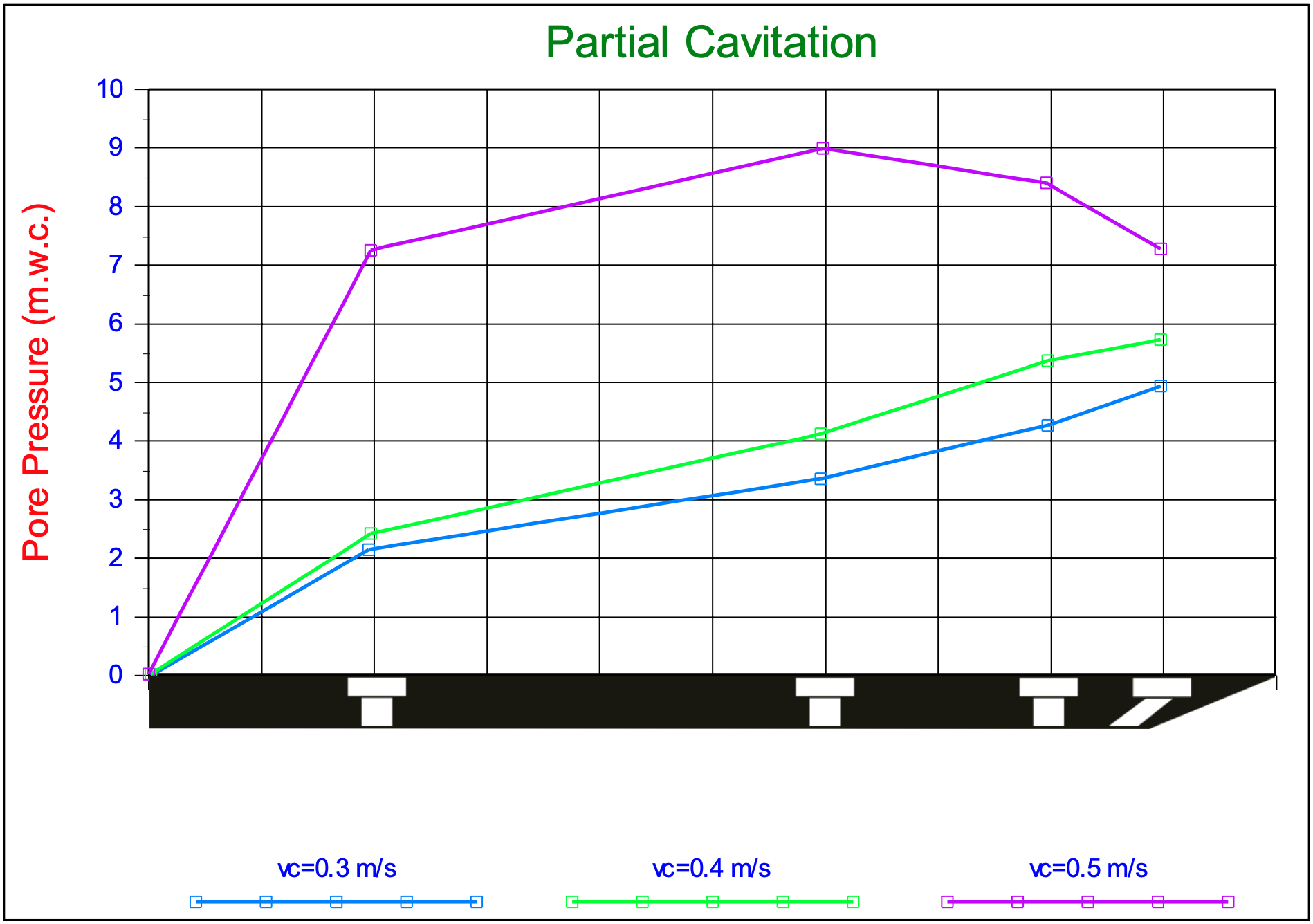
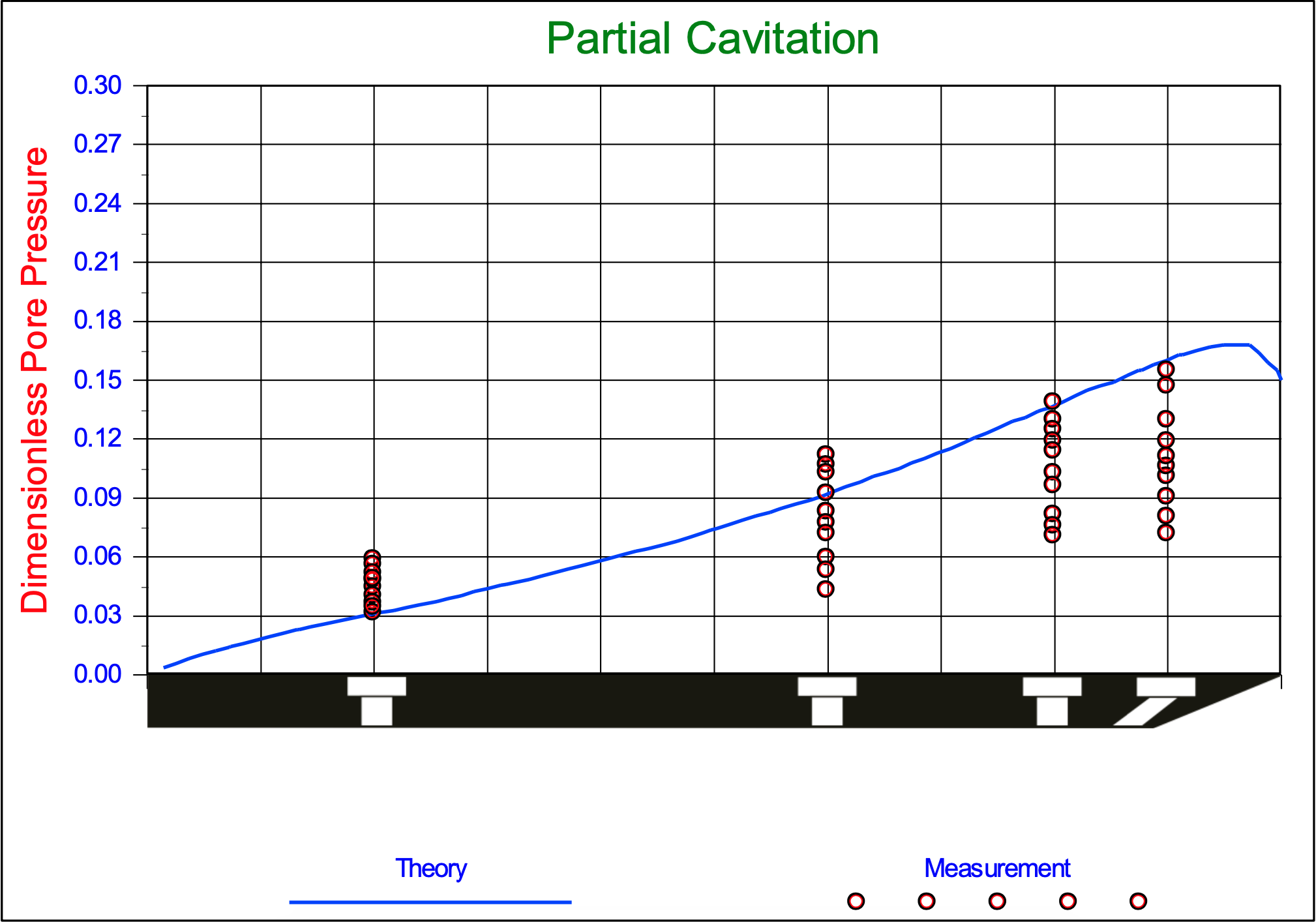
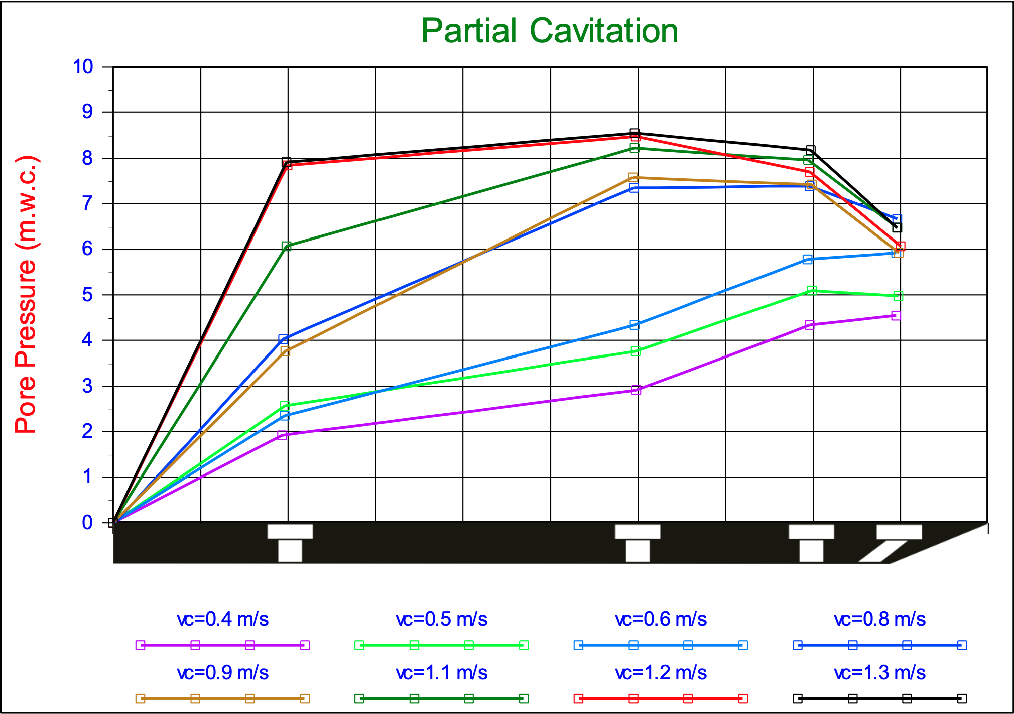
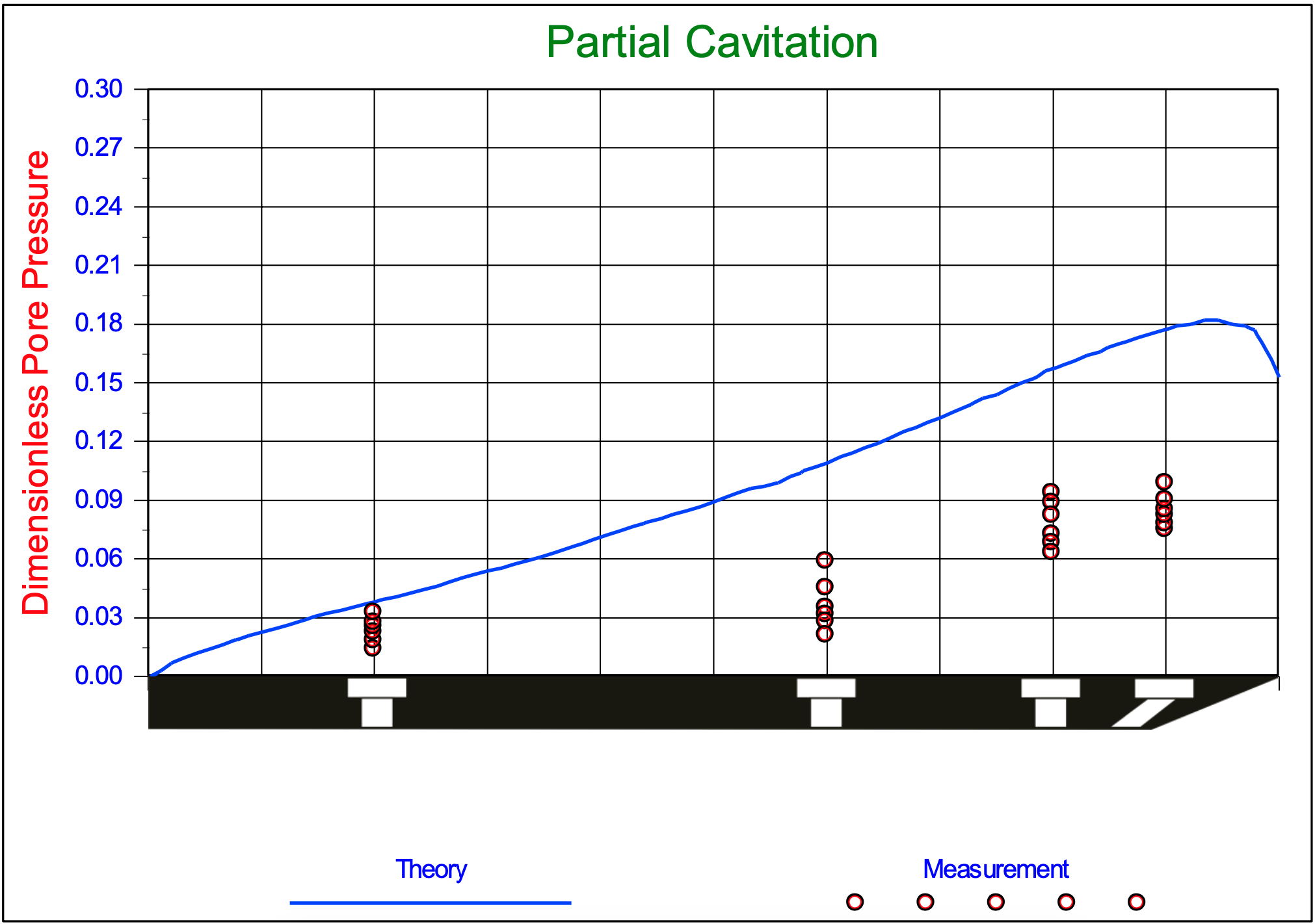
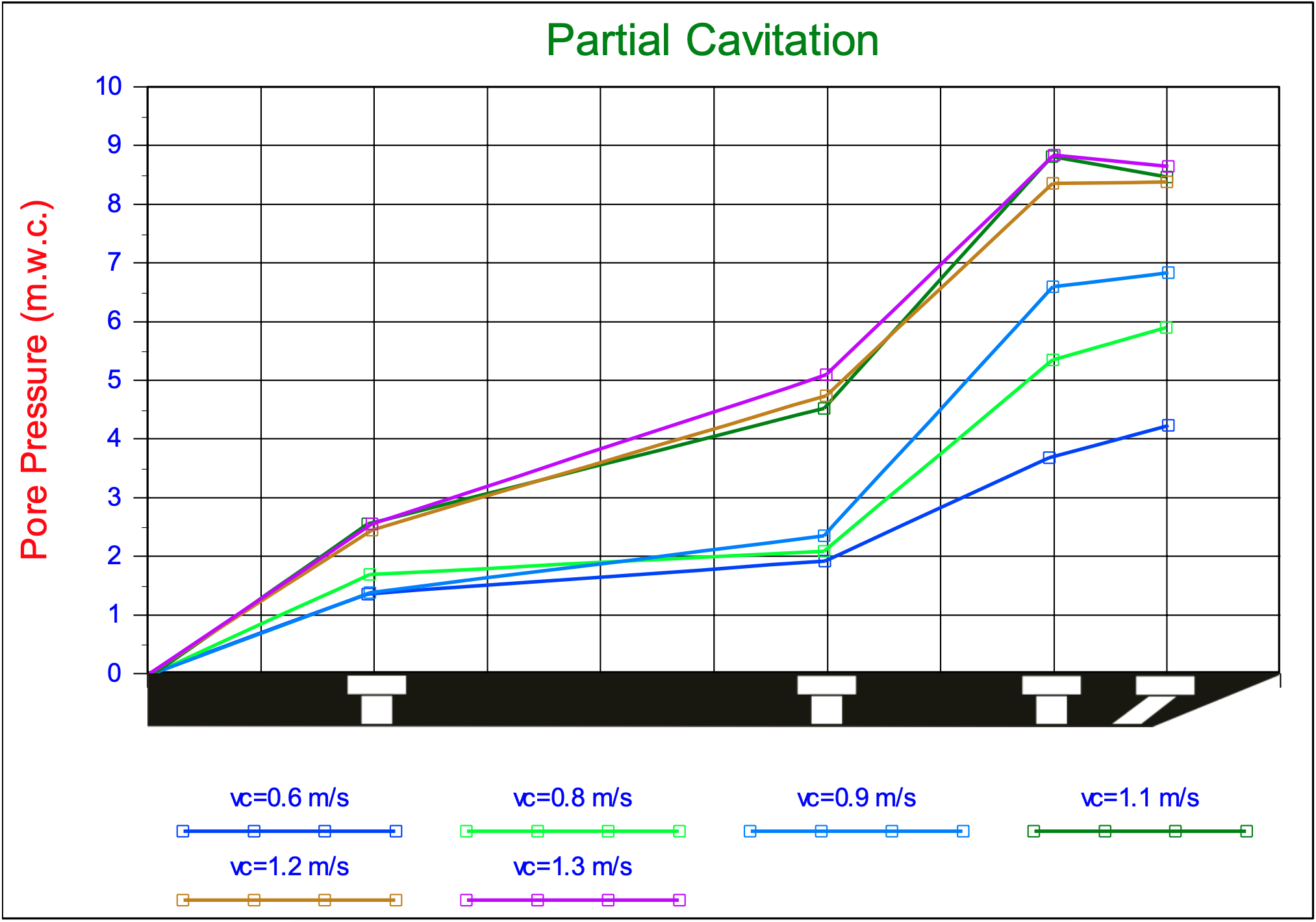
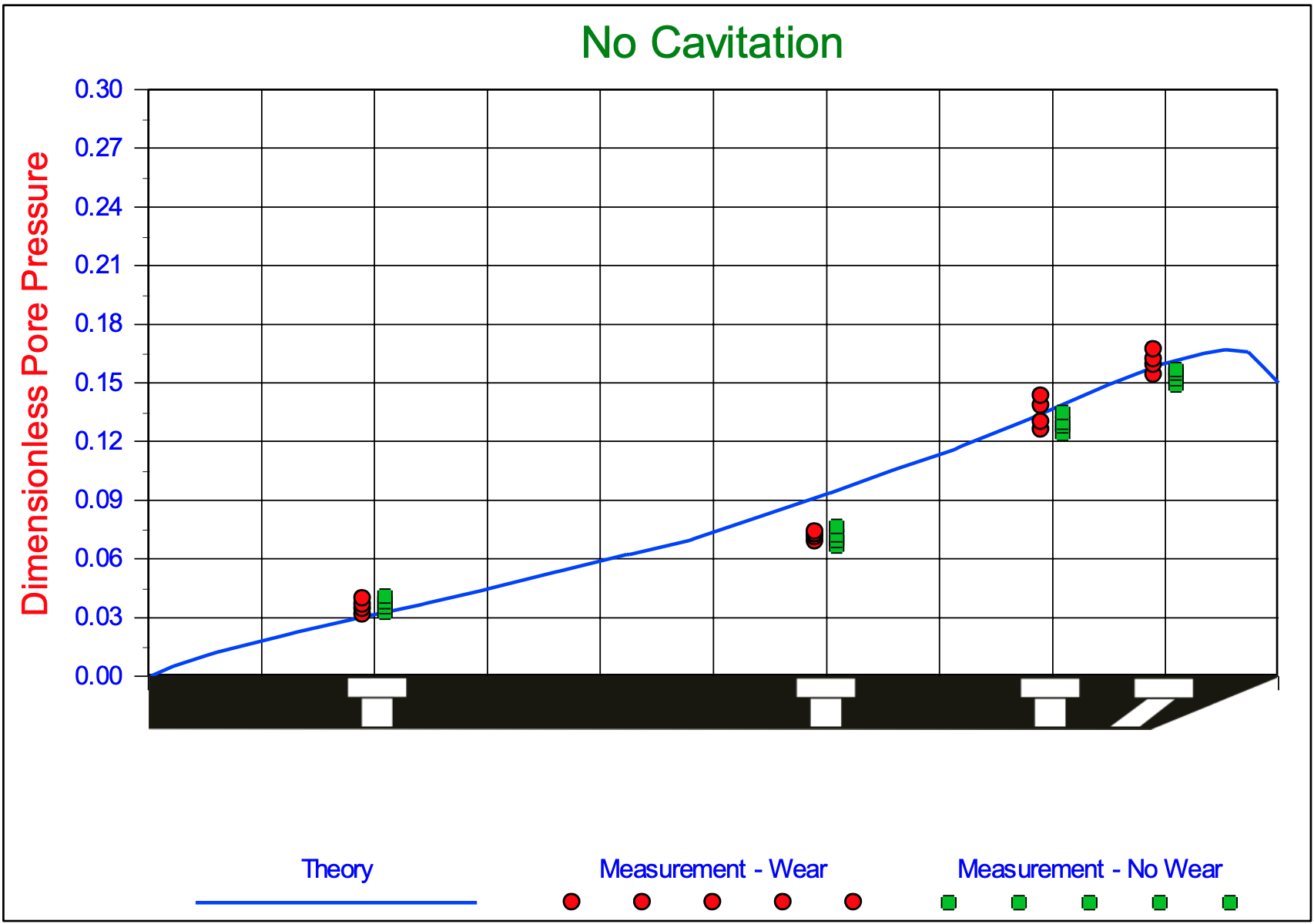
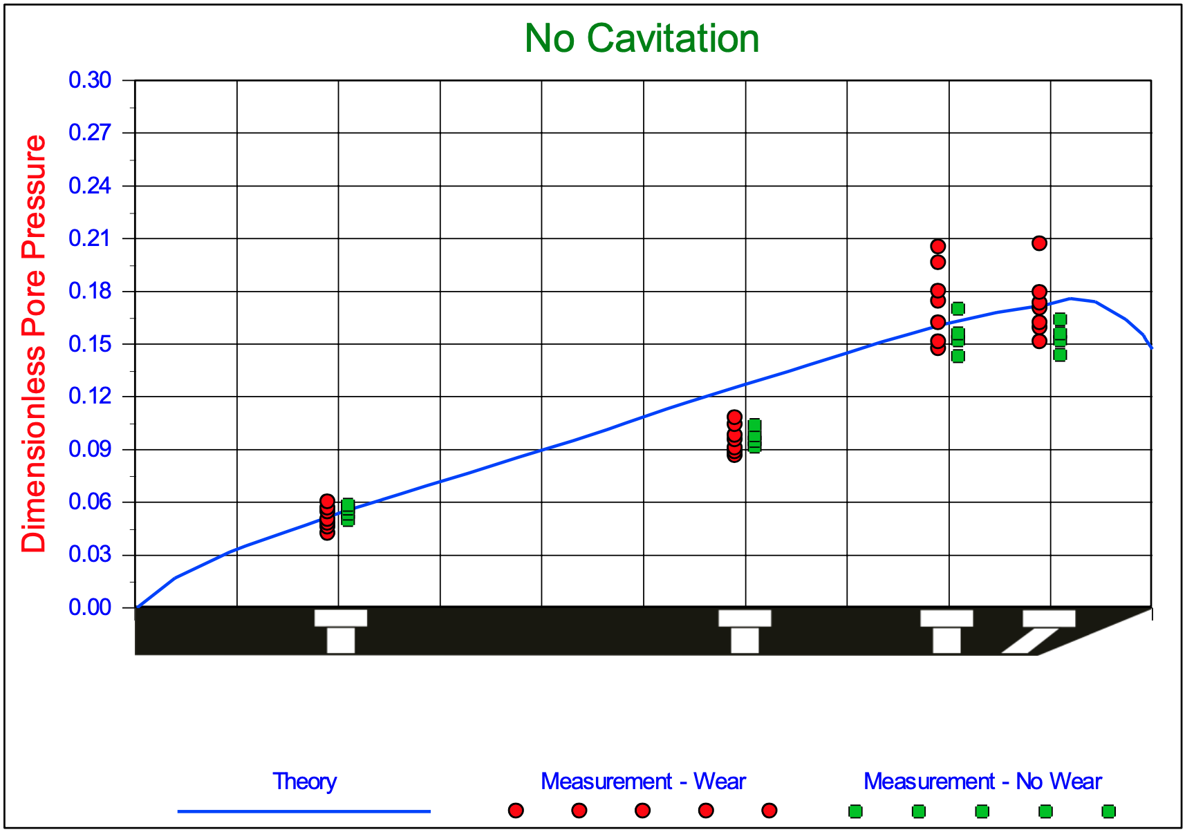
The dimensionless water pore pressures on the blade. Experiments in 200 μm sand, with α=30°, β=30o, φ=38o, δ=30o, ni=38.53%, nmax=43.88%, ki=0.000165 m/s, kmax=0.000320 m/s, hi=33 mm, hb=100 mm, w=0.2 m, z=0.6 m and a non-cavitating cutting process.
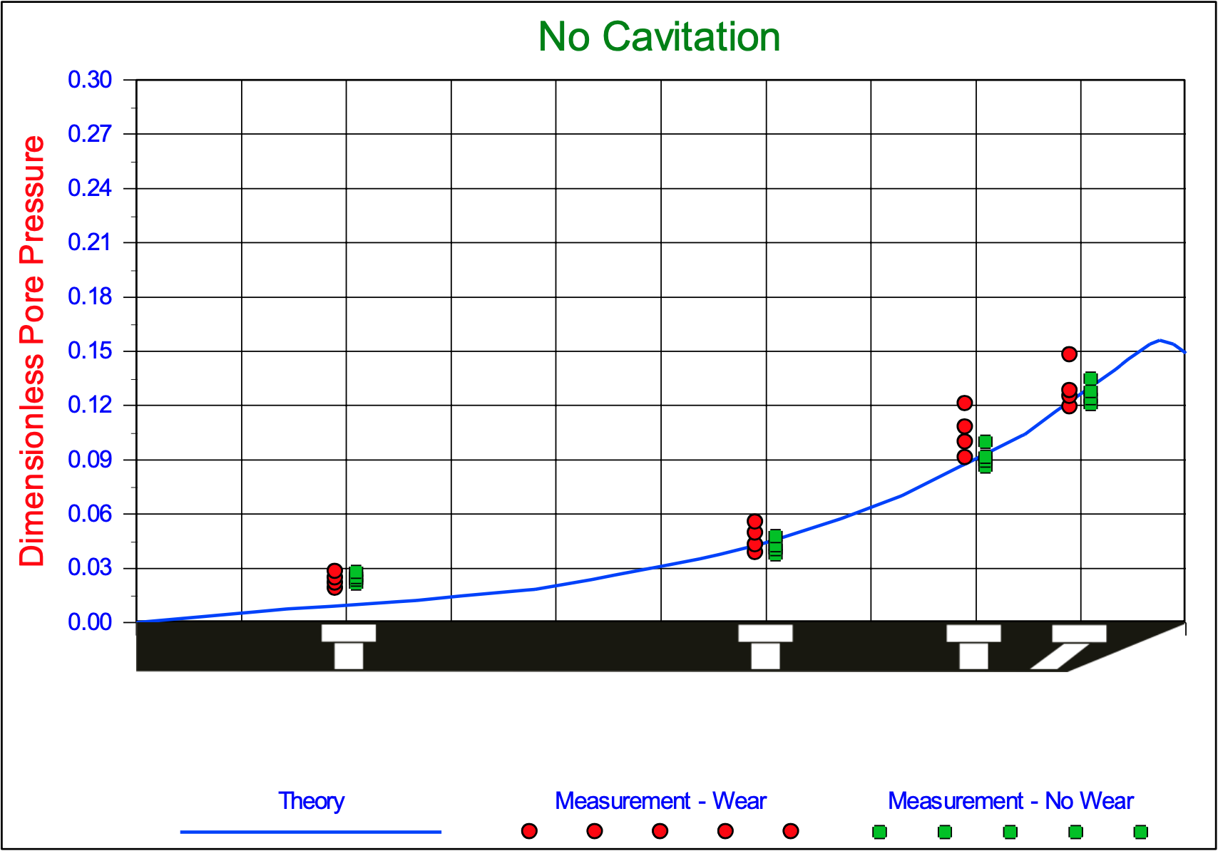
The dimensionless water pore pressures on the blade. Experiments in 200 μm sand, with α=30°, β=29°, φ=38°, δ=30°, ni=38.53%, nmax=43.88%, ki=0.000165 m/s, kmax=0.000320 m/s, hi=50 mm, hb=100 mm, w=0.2 m, z=0.6 m and a non-cavitating cutting process.
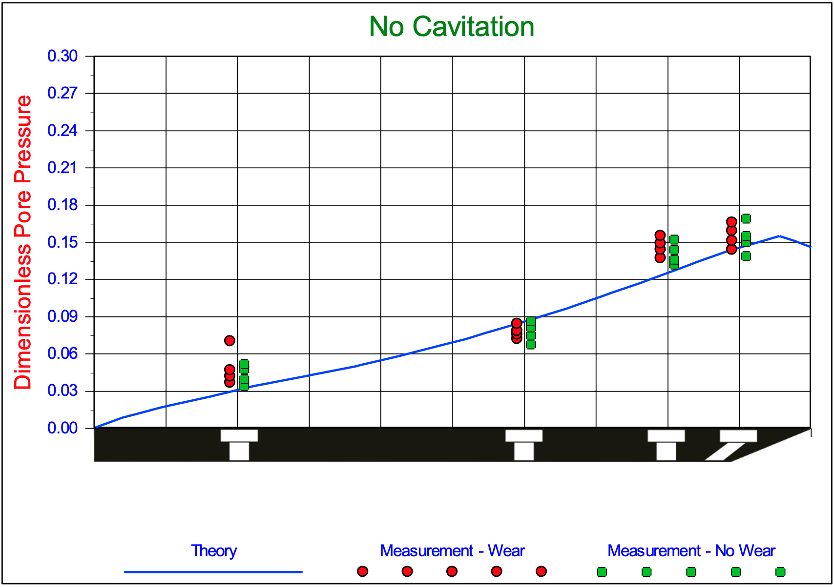
The dimensionless water pore pressures on the blade. Experiments in 200 μm sand, with α=30°, β=29°, φ=38°, δ=30°, ni=38.53%, nmax=43.88%, ki=0.000165 m/s, kmax=0.000320 m/s, hi=100 mm, hb=100 mm, w=0.2 m, z=0.6 m and a non-cavitating cutting process.
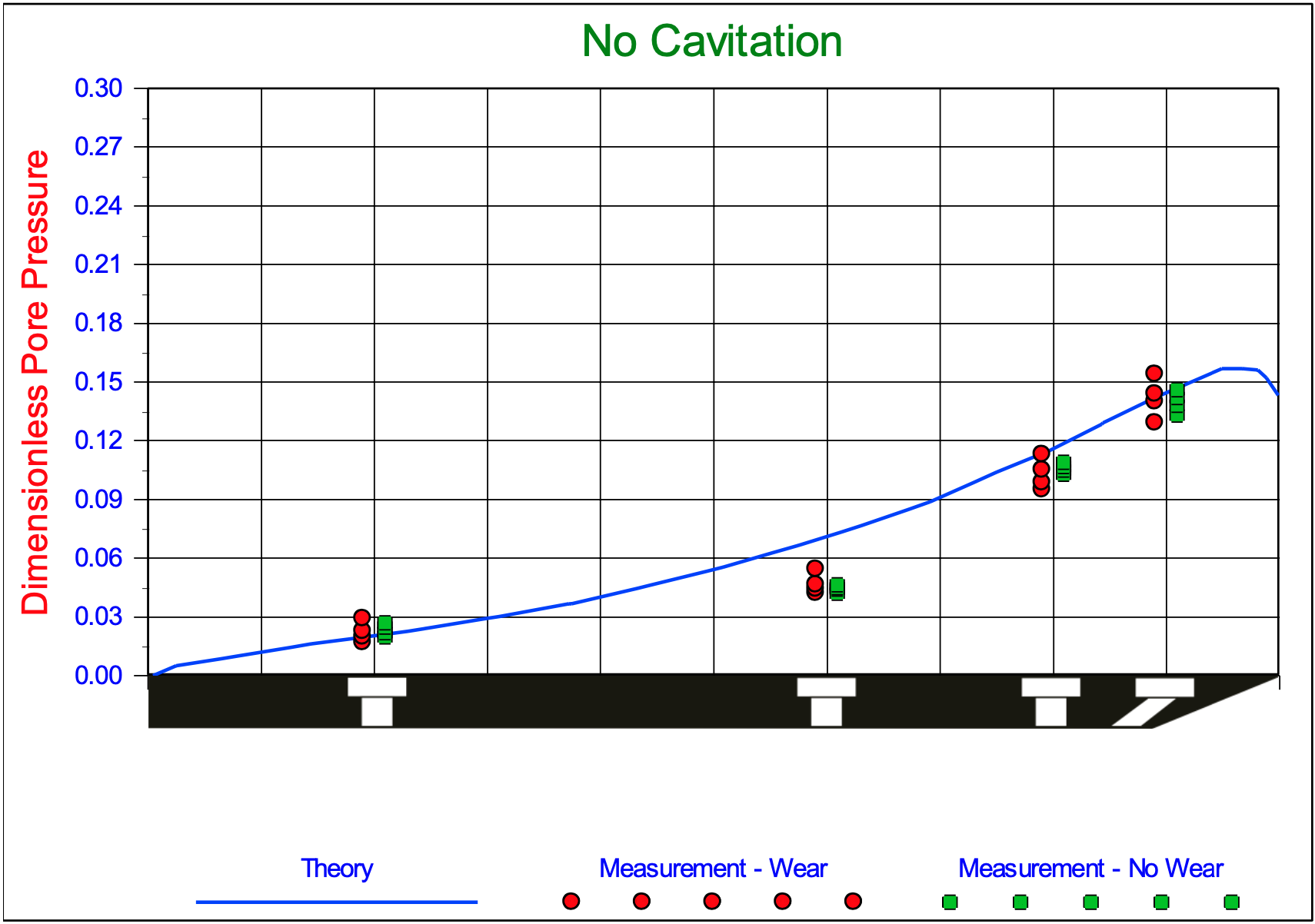
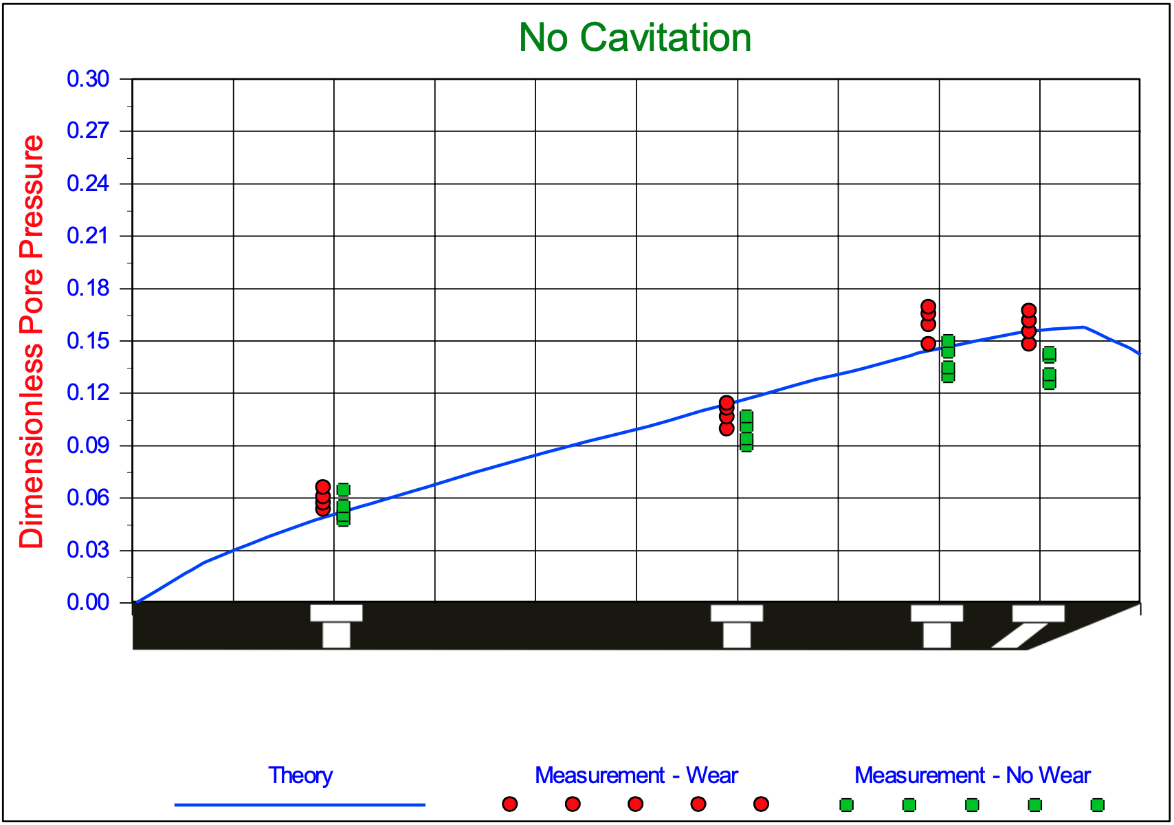
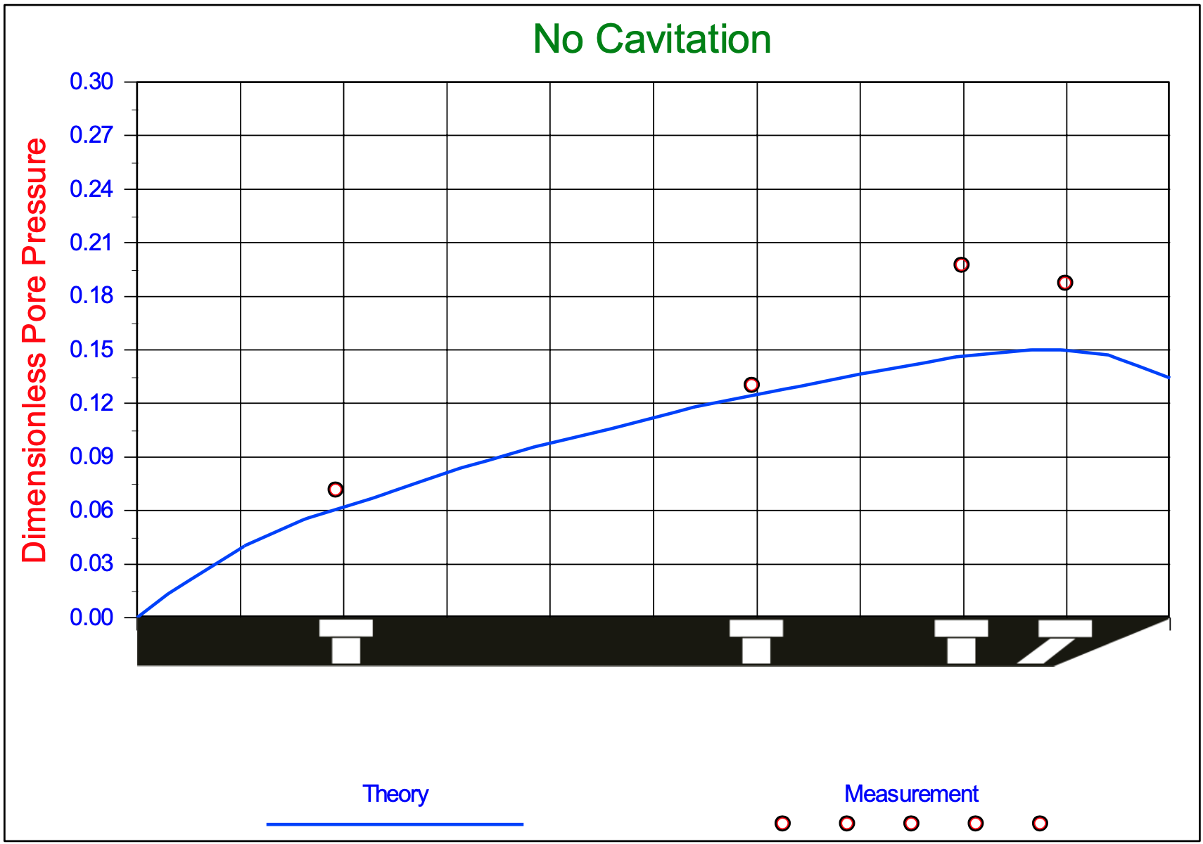
The dimensionless water pore pressures on the blade. Experiments in 200 μm sand, with α=45°, β=25°, φ=38°, δ=30°, ni=38.53%, nmax=43.88%, ki=0.000165 m/s, kmax=0.000320 m/s, hi=47 mm, hb=141 mm, w=0.2 m, z=0.6 m and a non-cavitating cutting process.
The dimensionless water pore pressures on the blade. Experiments in 200 μm sand, with α=45°, β=24o, φ=38o, δ=30o, ni=38.53%, nmax=43.88%, ki=0.000165 m/s, kmax=0.000320 m/s, hi=70 mm, hb=141 mm, w=0.2 m, z=0.6 m and a non-cavitating cutting process.
The dimensionless water pore pressures on the blade. Experiments in 200 μm sand, with α=45°, β=25°, φ=38°, δ=30°, ni=38.53%, nmax=43.88%, ki=0.000165 m/s, kmax=0.000320 m/s, hi=141 mm, hb=141 mm, w=0.2 m, z=0.6 m and a non-cavitating cutting process.
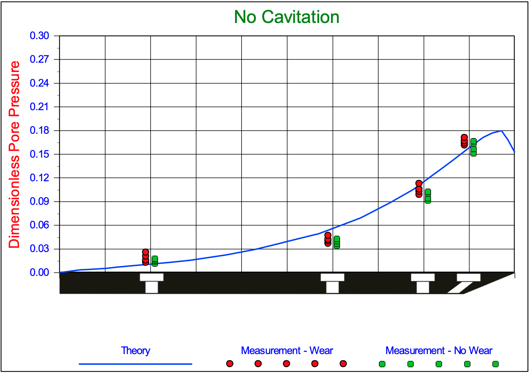
The dimensionless water pore pressures on the blade. Experiments in 200 μm sand, with α=60°, β=19o, φ=38o, δ=30o, ni=38.53%, nmax=43.88%, ki=0.000165 m/s, kmax=0.000320 m/s, hi=30 mm, hb=173 mm, w=0.2 m, z=0.6 m and a non-cavitating cutting process.
The dimensionless water pore pressures on the blade. Experiments in 200 μm sand, with α=60°, β=19o, φ=38o, δ=30o, ni=38.53%, nmax=43.88%, ki=0.000165 m/s, kmax=0.000320 m/s, hi=58 mm, hb=173 mm, w=0.2 m, z=0.6 m and a non-cavitating cutting process.
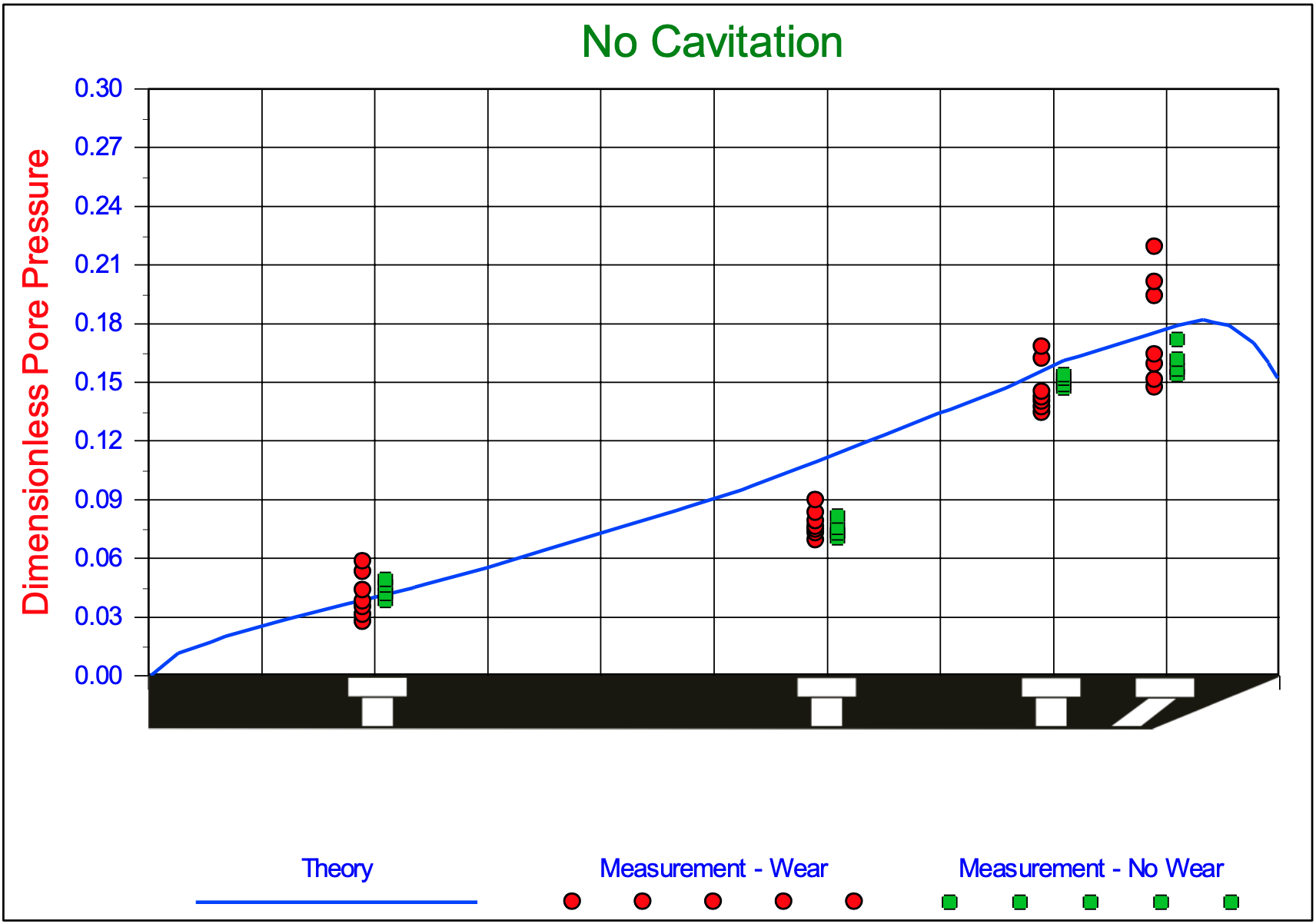
The dimensionless water pore pressures on the blade. Experiments in 200 μm sand, with α=60°, β=19°, φ=38°, δ=30°, ni=38.53%, nmax=43.88%, ki=0.000165 m/s, kmax=0.000320 m/s, hi=87 mm, hb=173 mm, w=0.2 m, z=0.6 m and a non-cavitating cutting process.
The dimensionless water pore pressures on the blade. Experiments in 200 μm sand, with α=60°, β=20°, φ=38o, δ=30°, ni=38.53%, nmax=43.88%, ki=0.000165 m/s, kmax=0.000320 m/s, hi=173 mm, hb=173 mm, w=0.2 m, z=0.6 m and a non-cavitating cutting process.
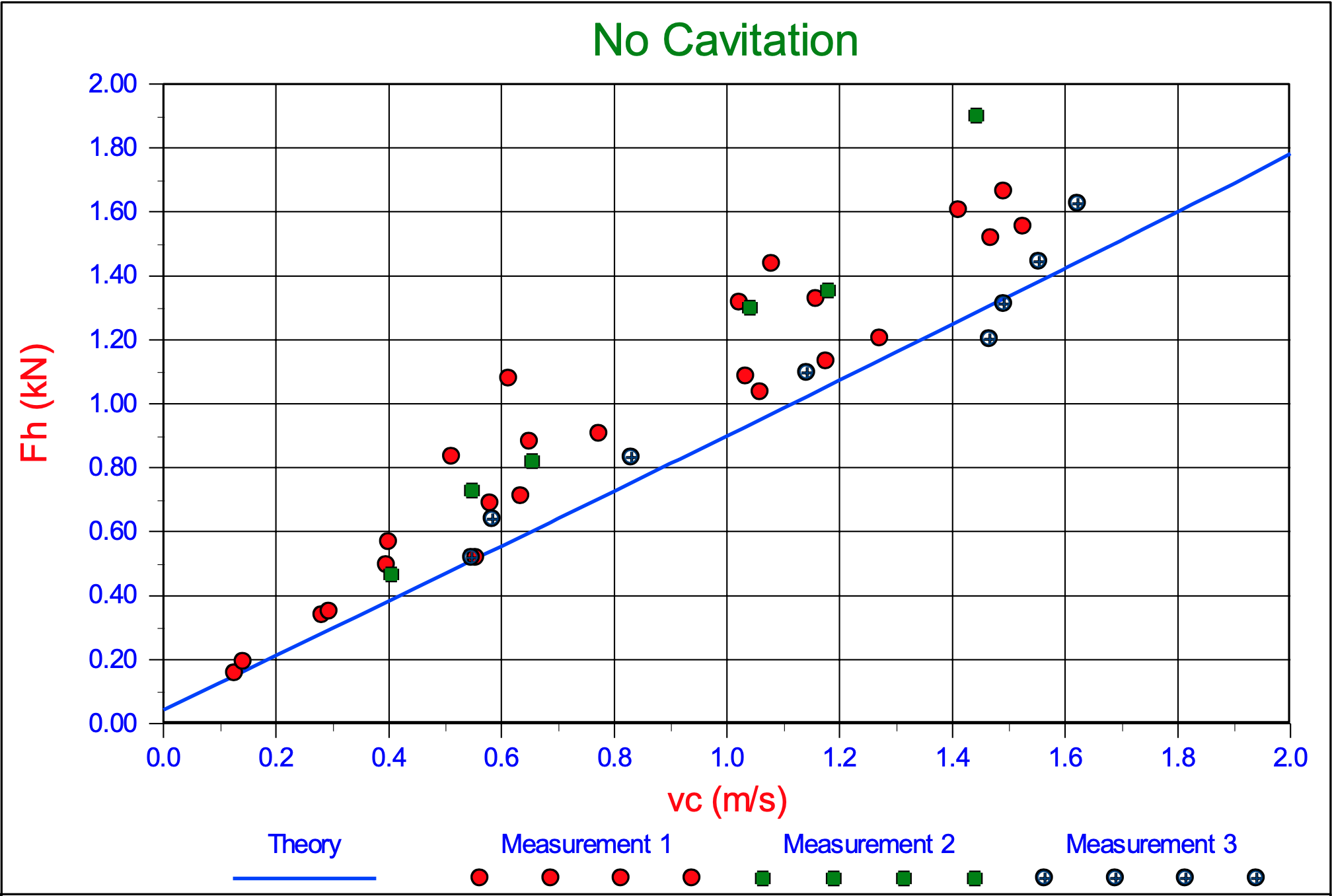
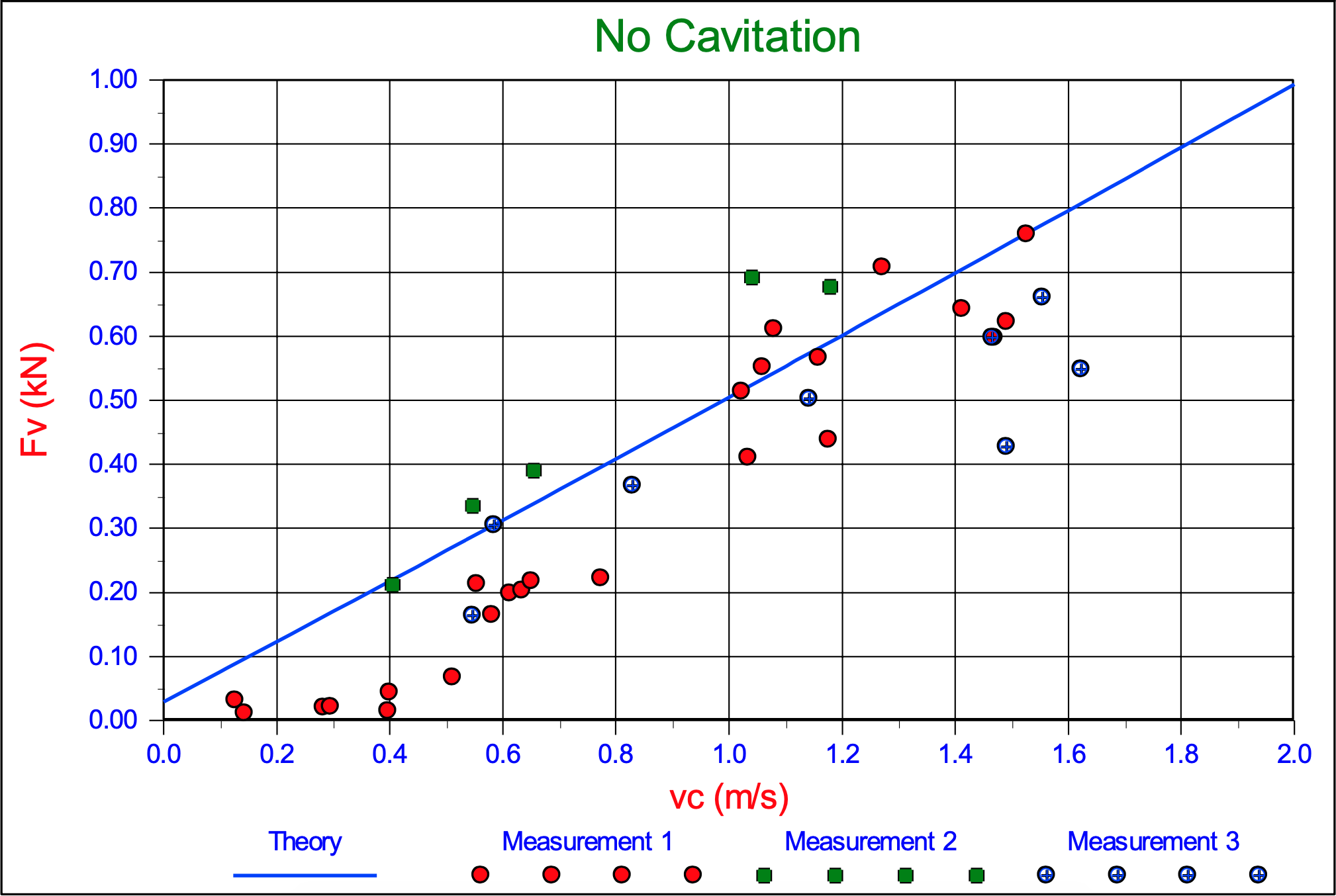
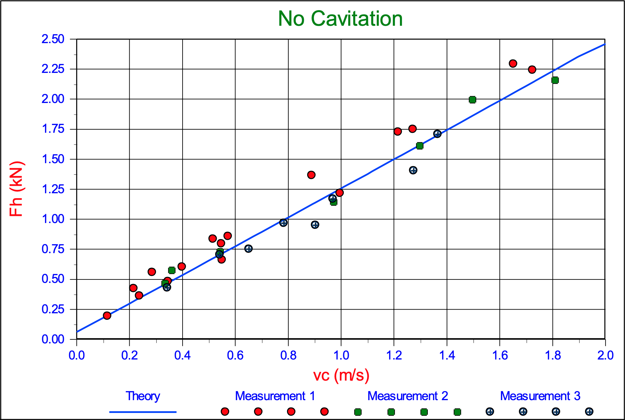
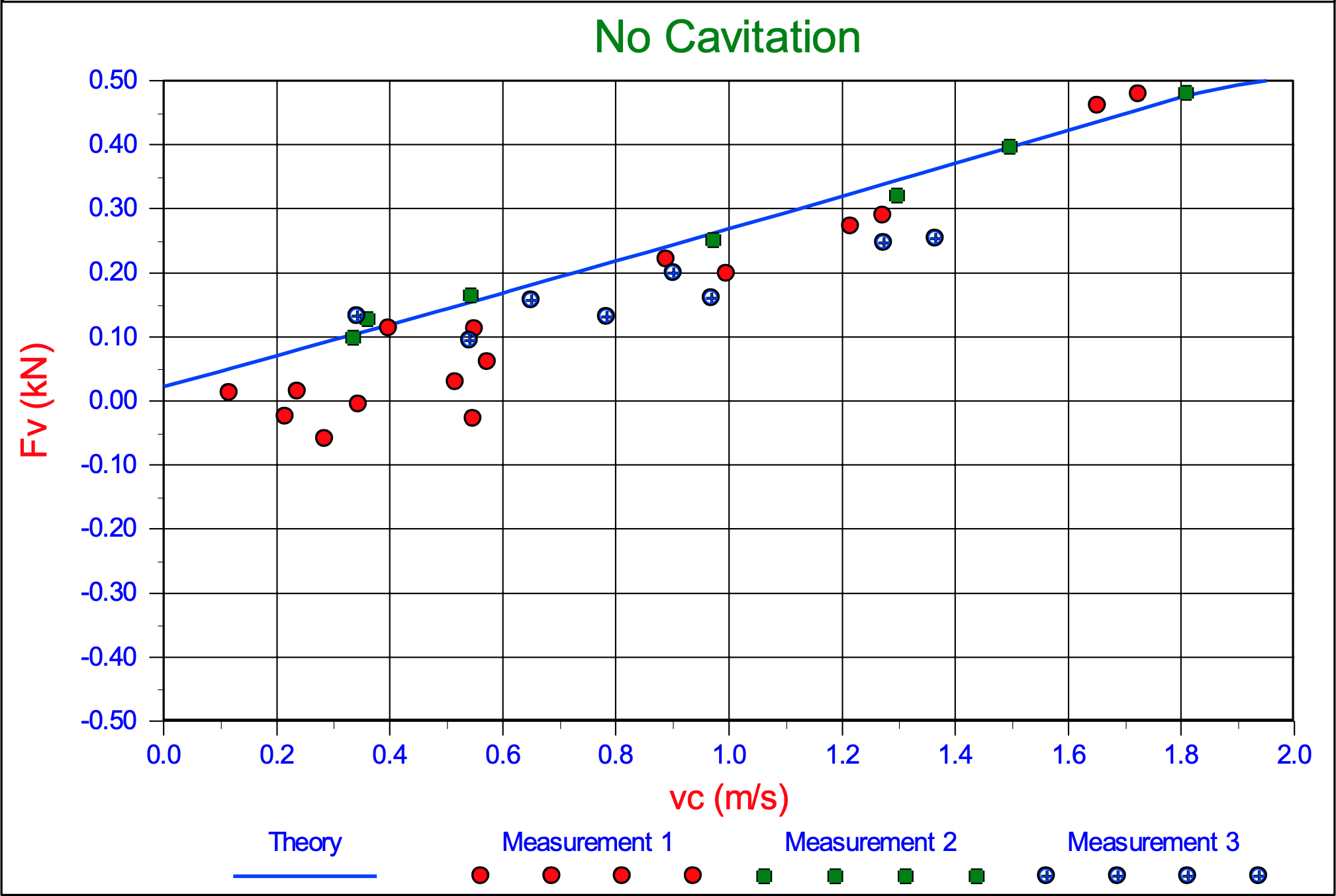
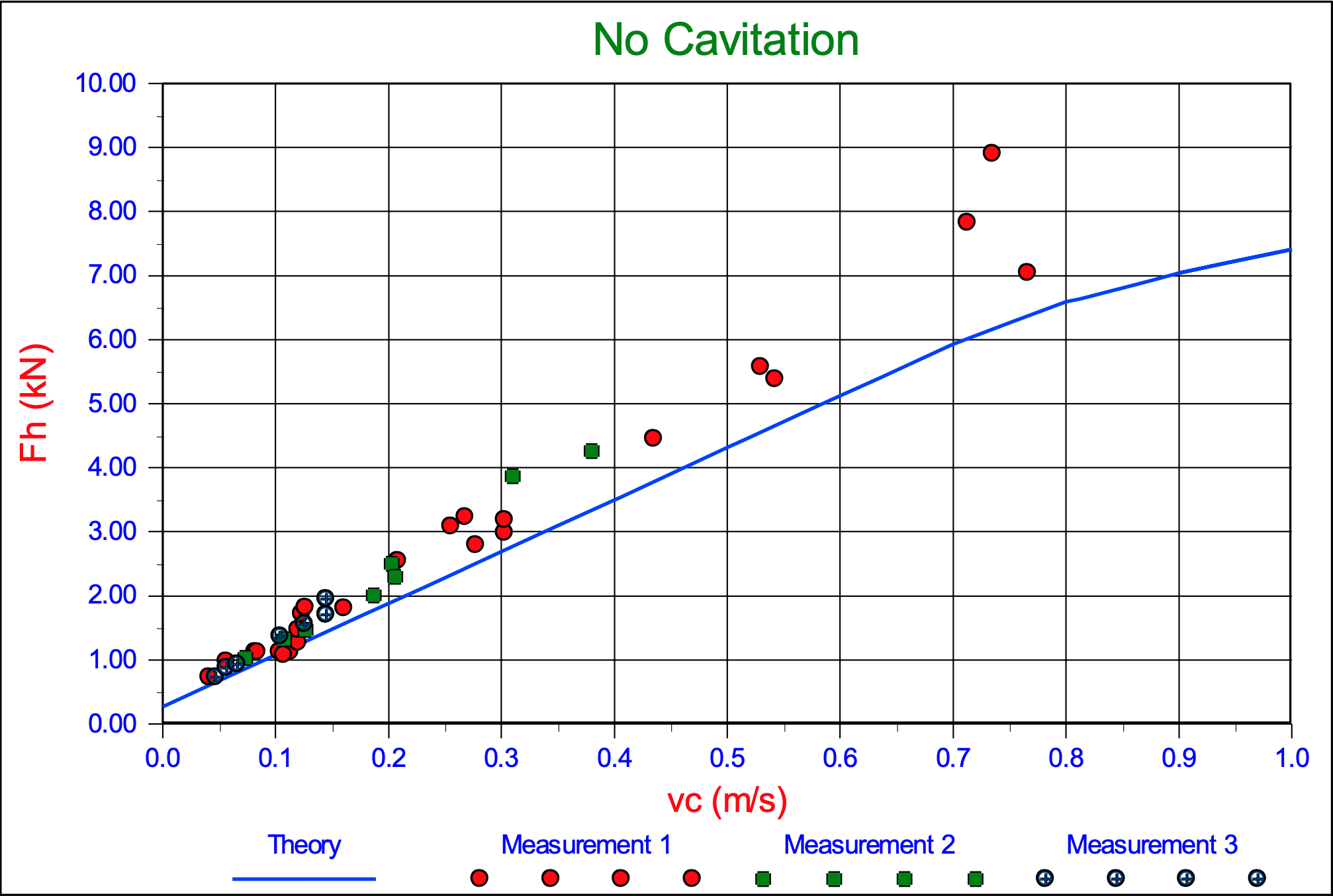
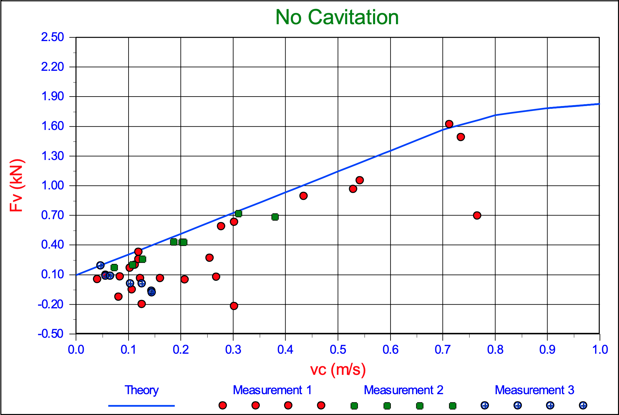
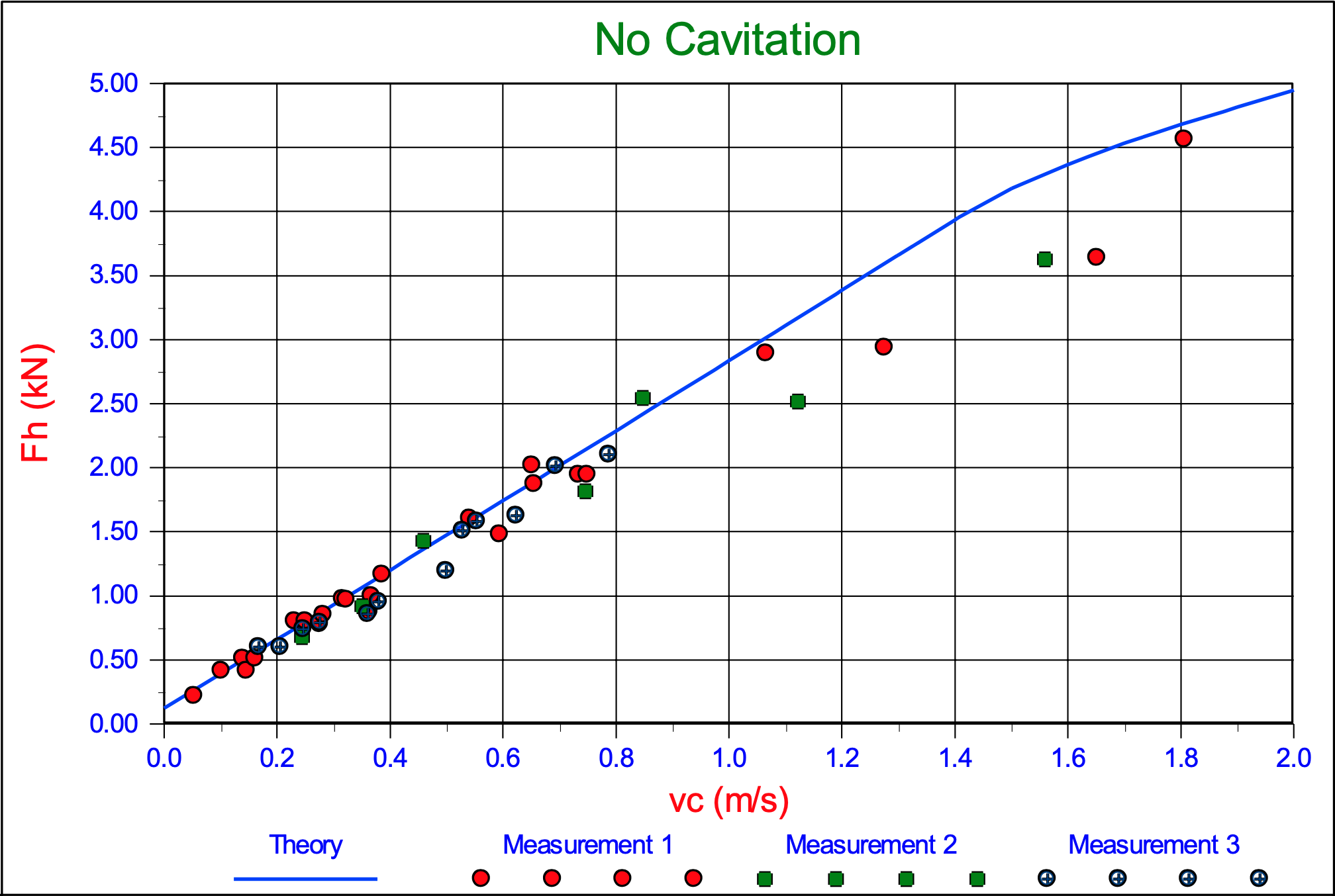
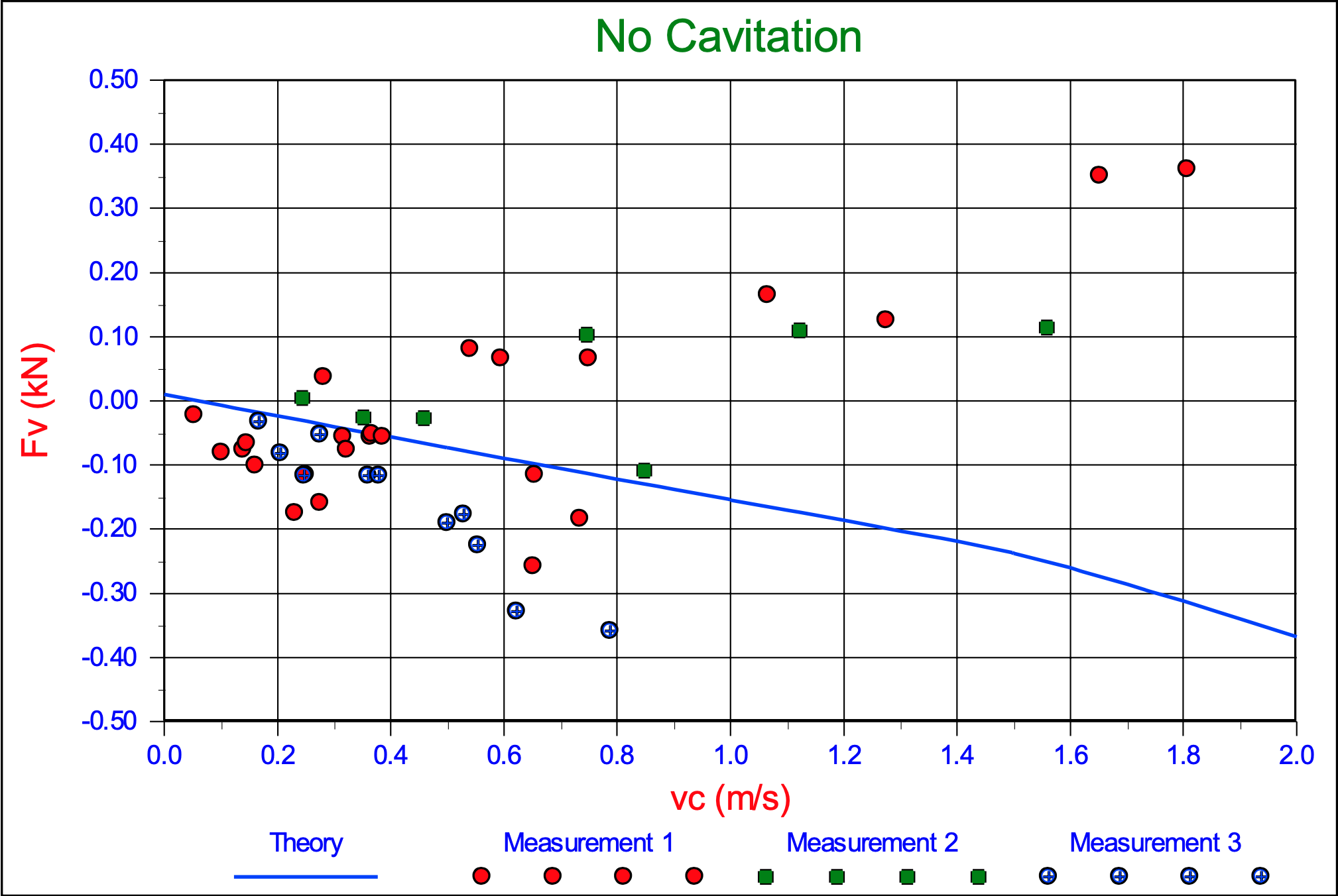
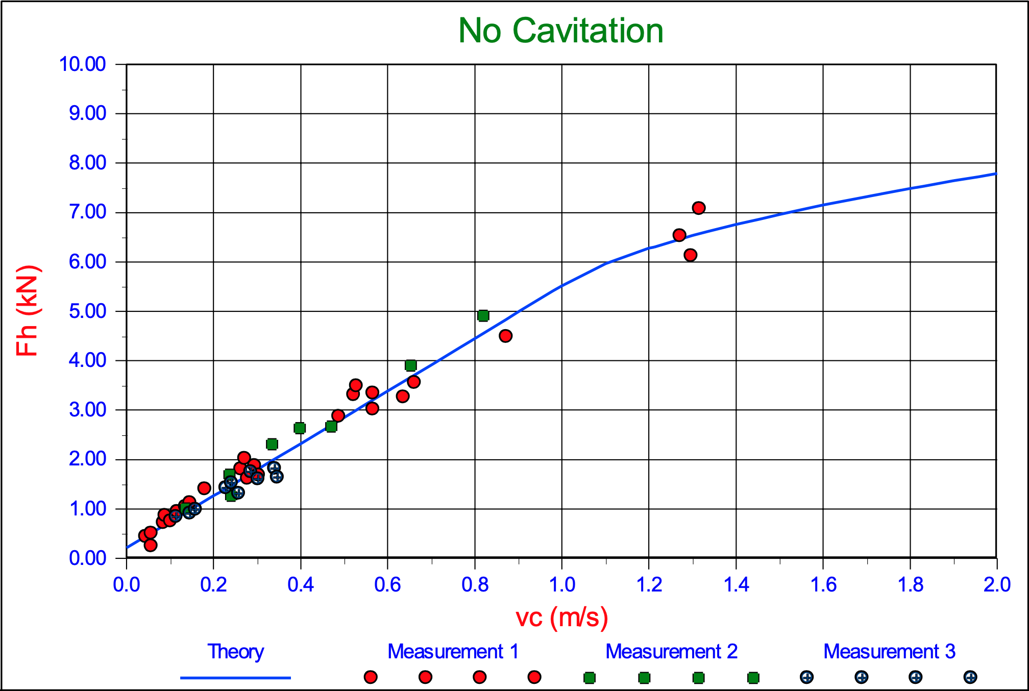
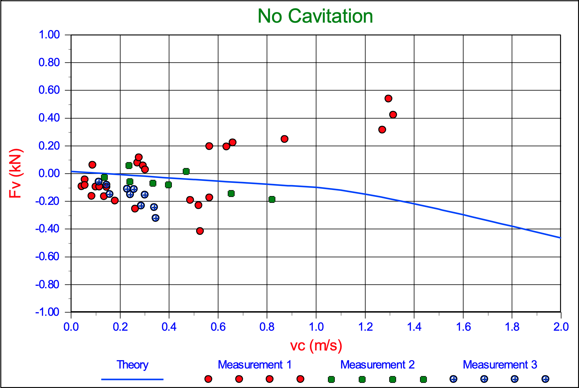
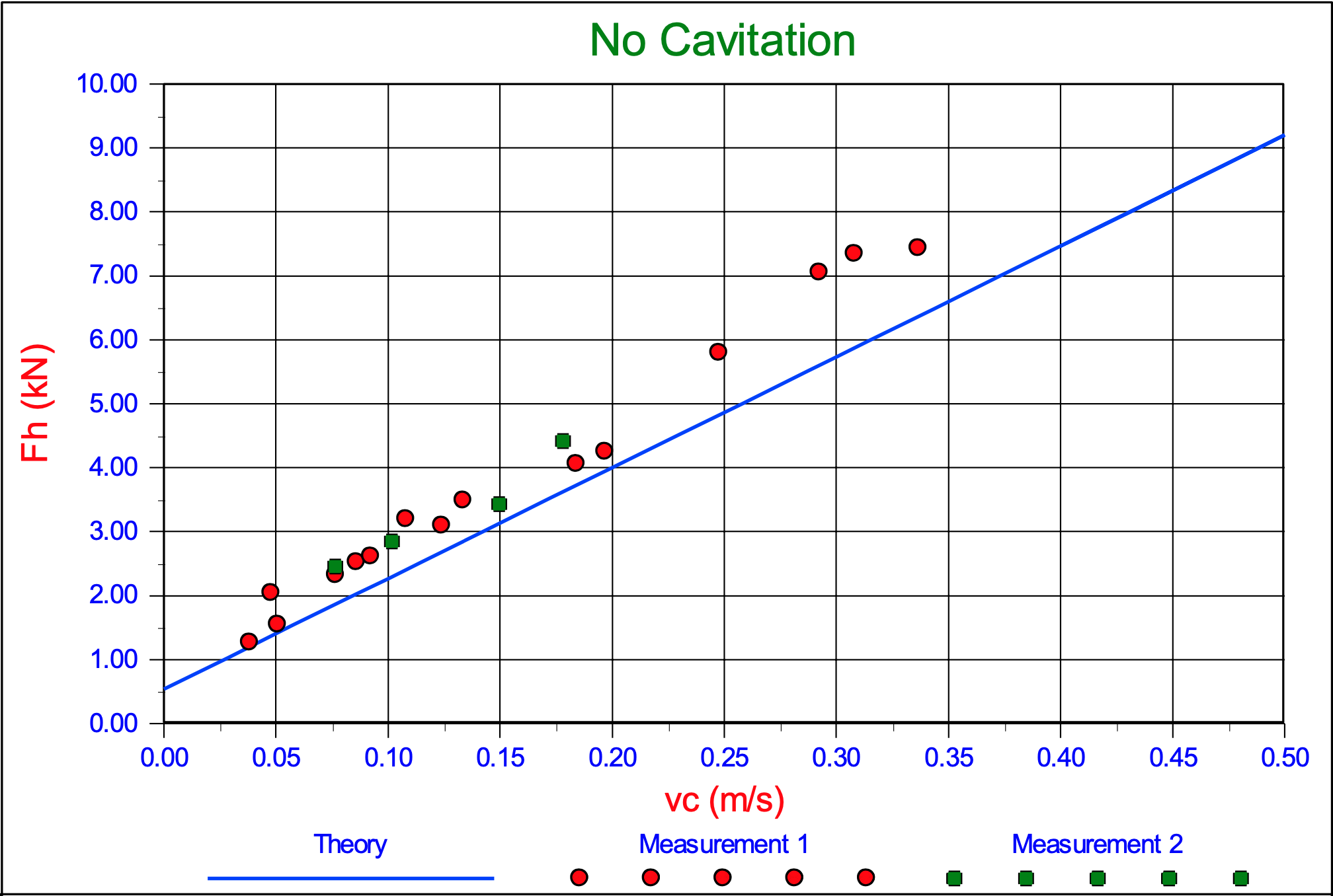
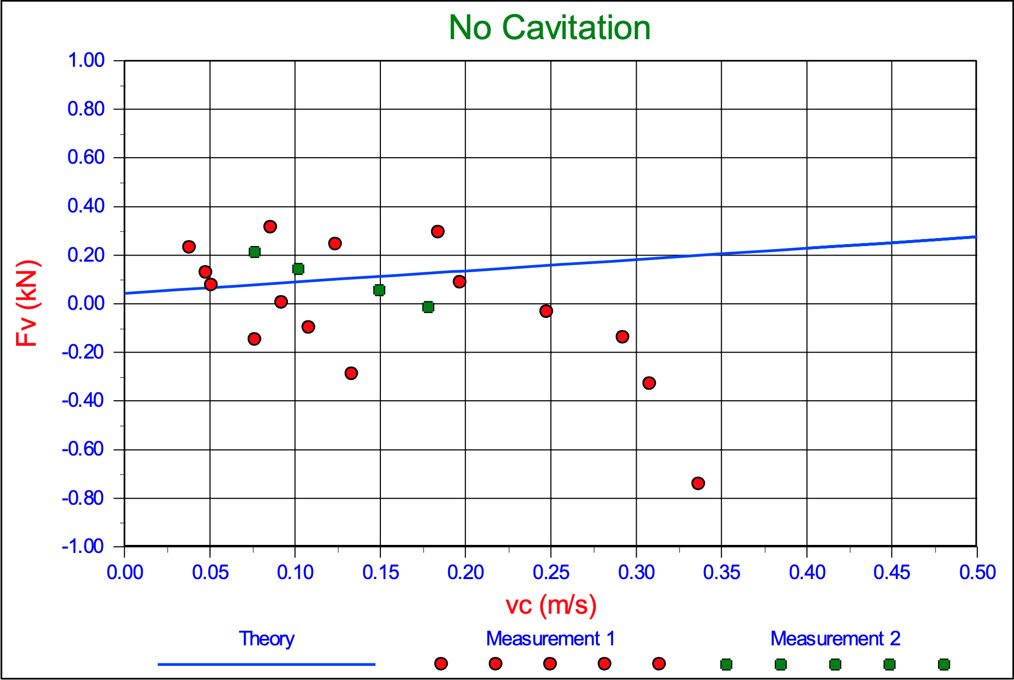
M.3 Cutting Forces in 200 μm Sand
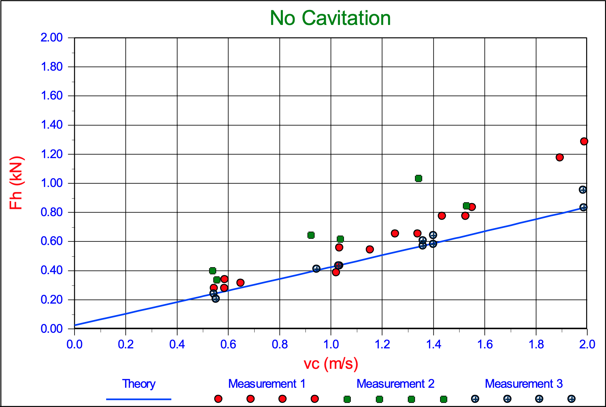
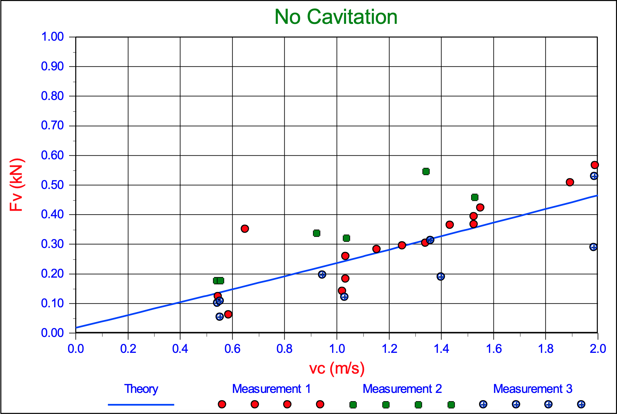
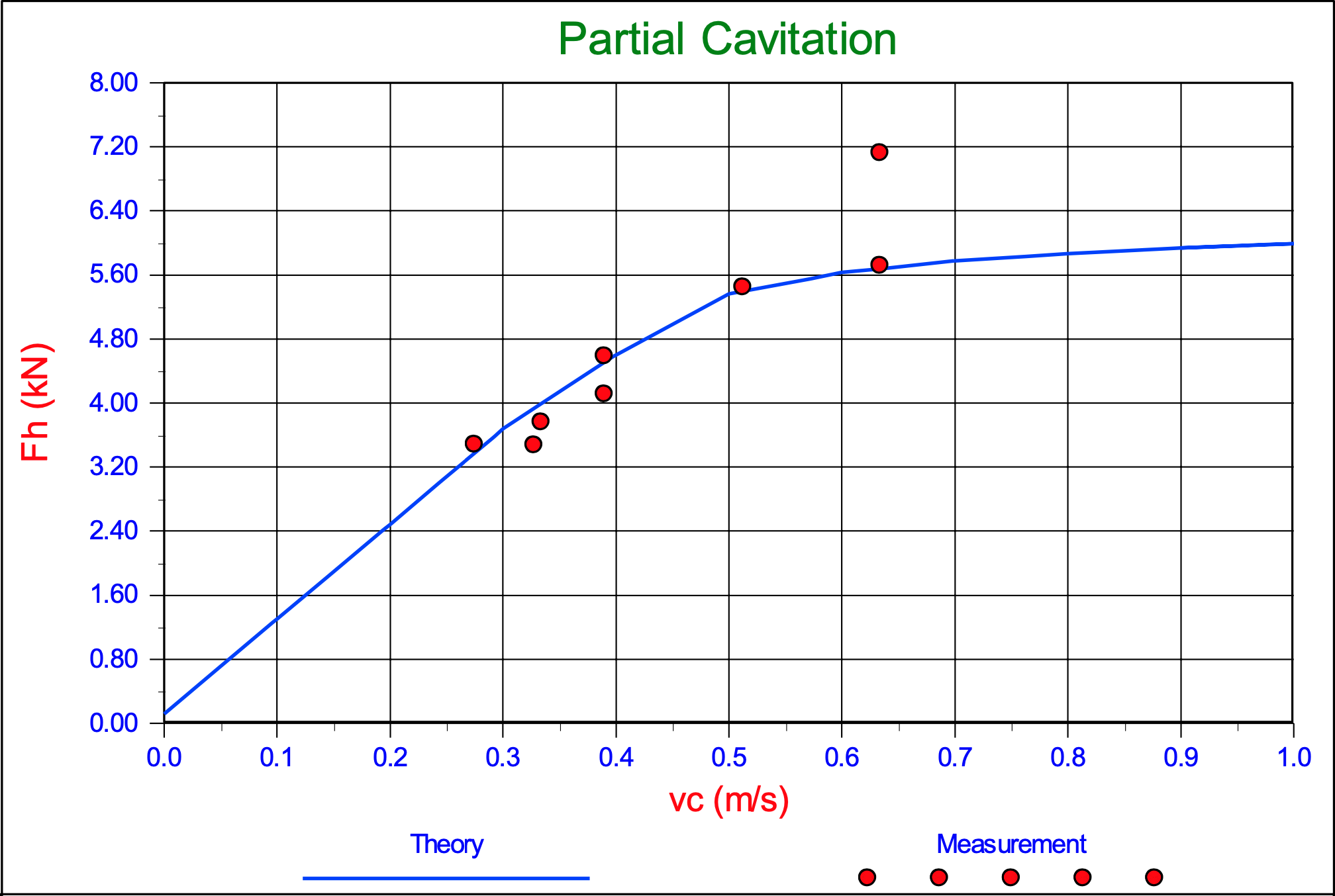
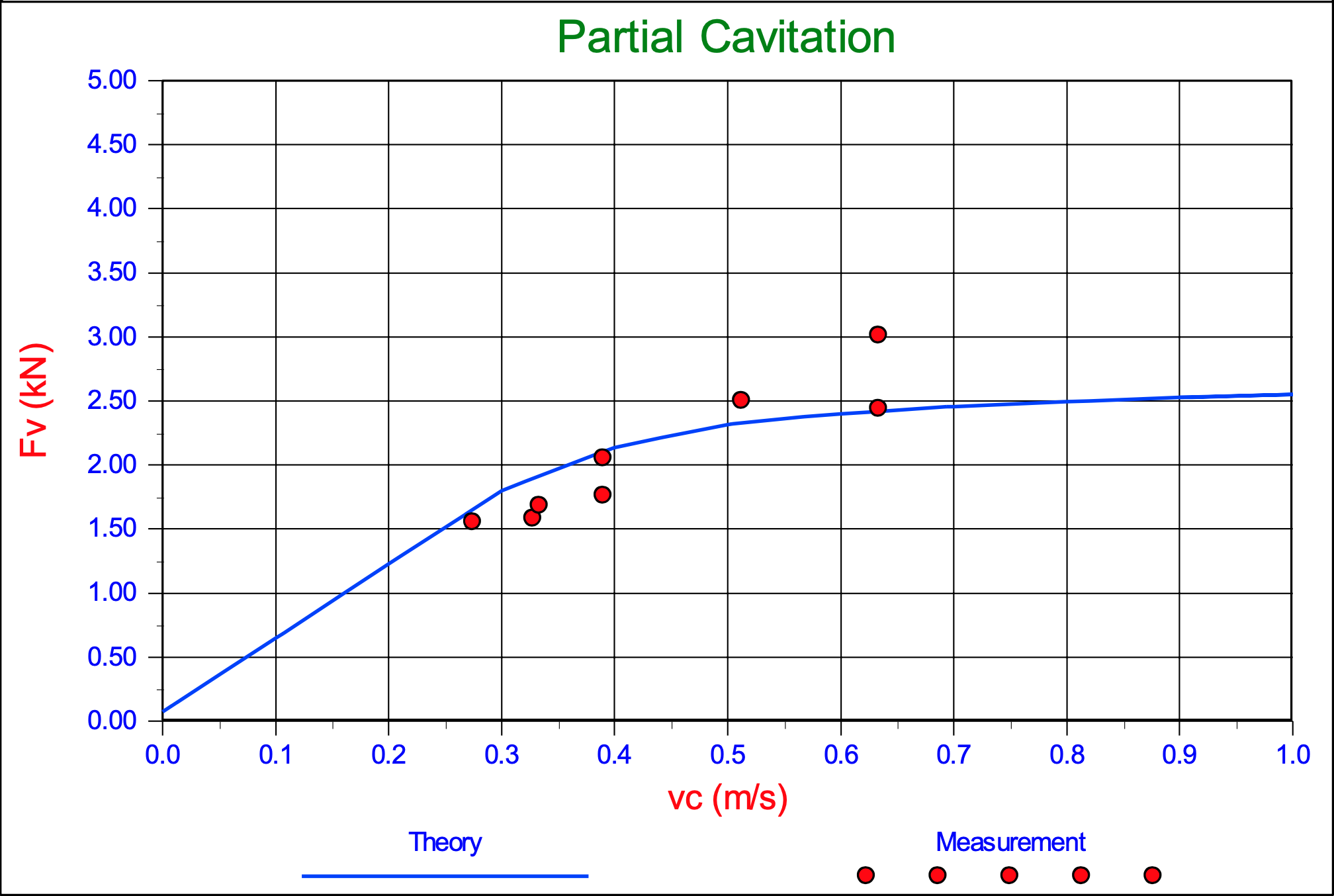
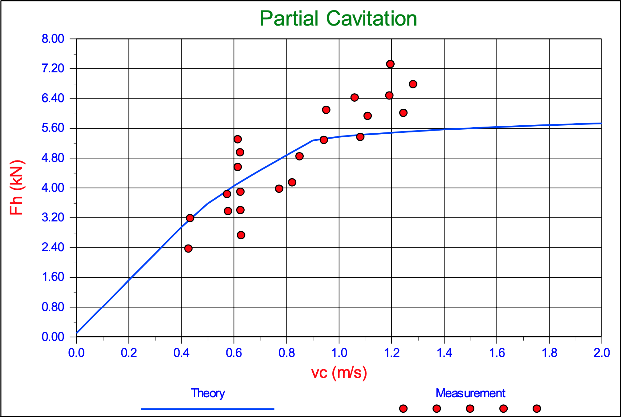
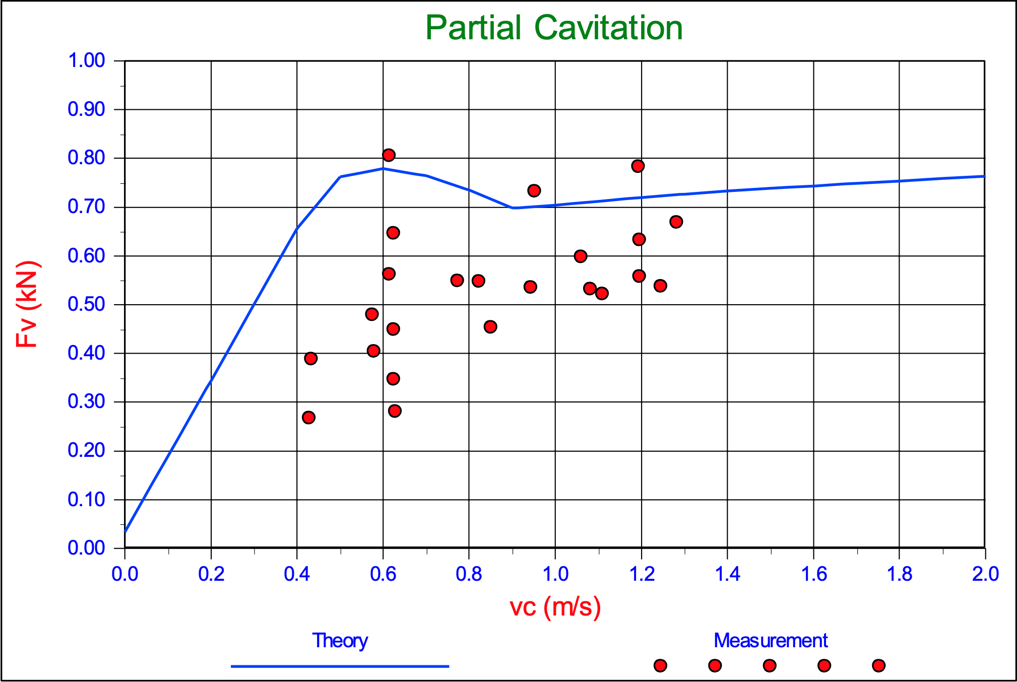
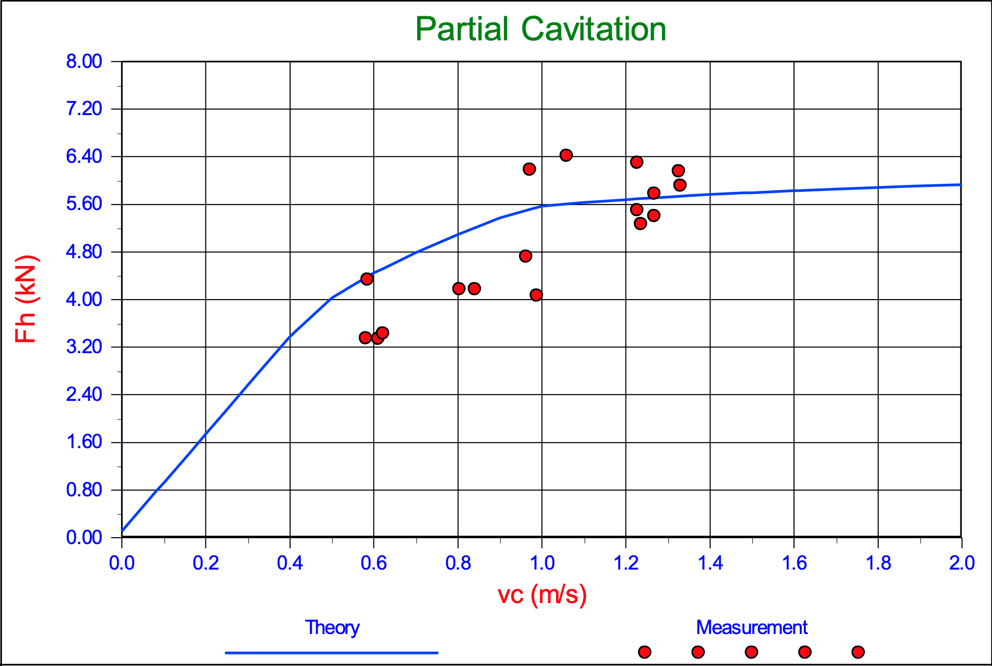
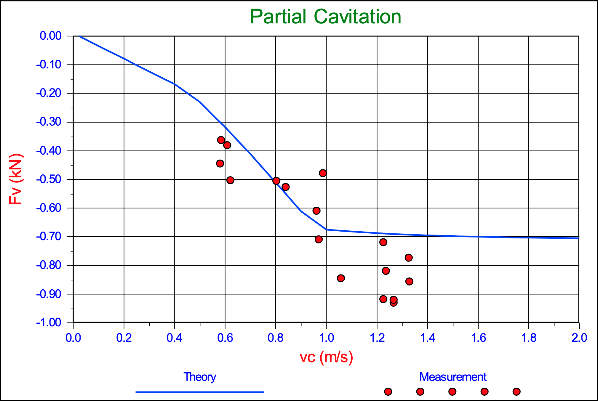
The cutting forces Fh and Fv on the blade. Experiments in 200 μm sand, with α=30°, β=30°, φ=38°, δ=30°, ni=38.53%, nmax=43.88%, ki=0.000165 m/s, kmax=0.000320 m/s, hi=33 mm, hb=100 mm, w=0.2 m, z=0.6 m and a non-cavitating cutting process.
The cutting forces Fh and Fv on the blade. Experiments in 200 μm sand, with α=30°, β=30°, φ=38°, δ=30°, ni=38.53%, nmax=43.88%, ki=0.000165 m/s, kmax=0.000320 m/s, hi=50 mm, hb=100 mm, w=0.2 m, z=0.6 m and a non-cavitating cutting process.
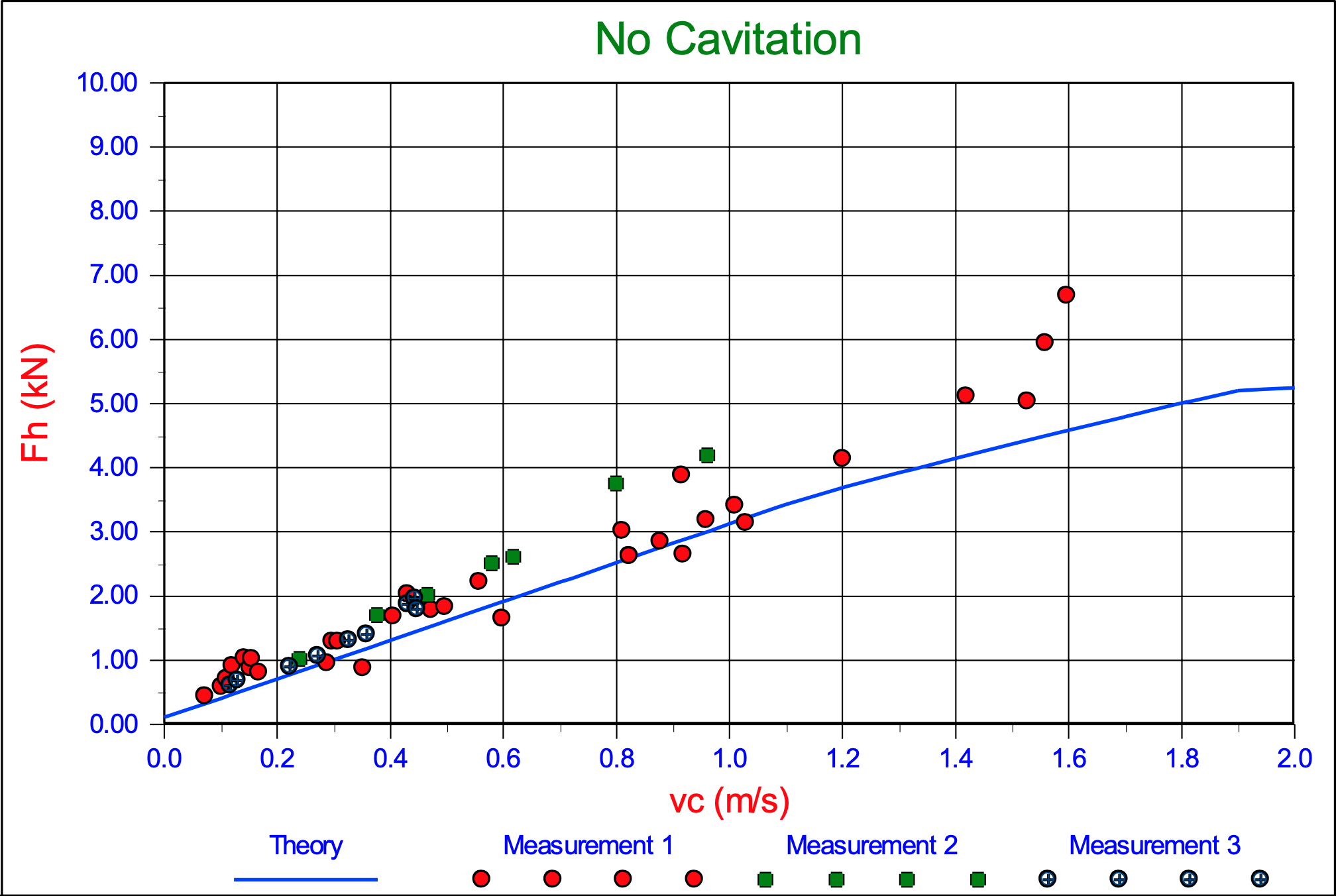
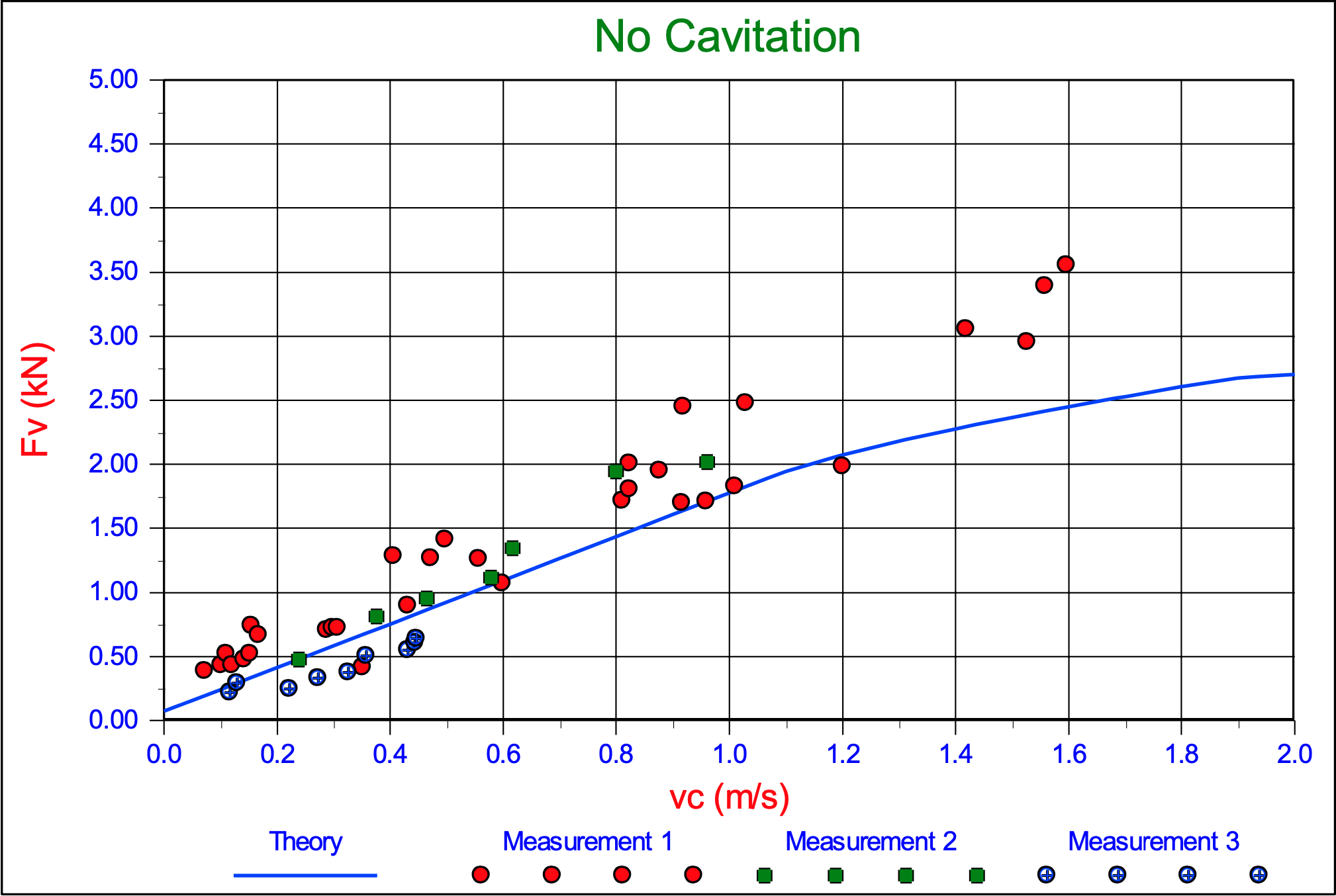
The cutting forces Fh and Fv on the blade. Experiments in 200 μm sand, with α=30°, β=30o, φ=38o, δ=30o, ni=38.53%, nmax=43.88%, ki=0.000165 m/s, kmax=0.000320 m/s, hi=100 mm, hb=100 mm, w=0.2 m, z=0.6 m and a non-cavitating cutting process.
The cutting forces Fh and Fv on the blade. Experiments in 200 μm sand, with α=45°, β=30o, φ=38°, δ=30°, ni=38.53%, nmax=43.88%, ki=0.000165 m/s, kmax=0.000320 m/s, hi=47 mm, hb=141 mm, w=0.2 m, z=0.6 m and a non-cavitating cutting process.
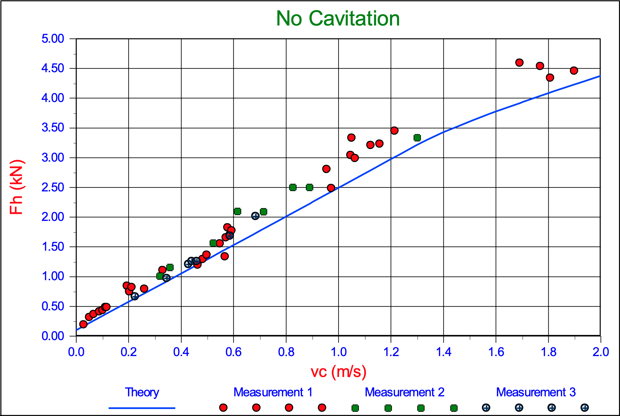
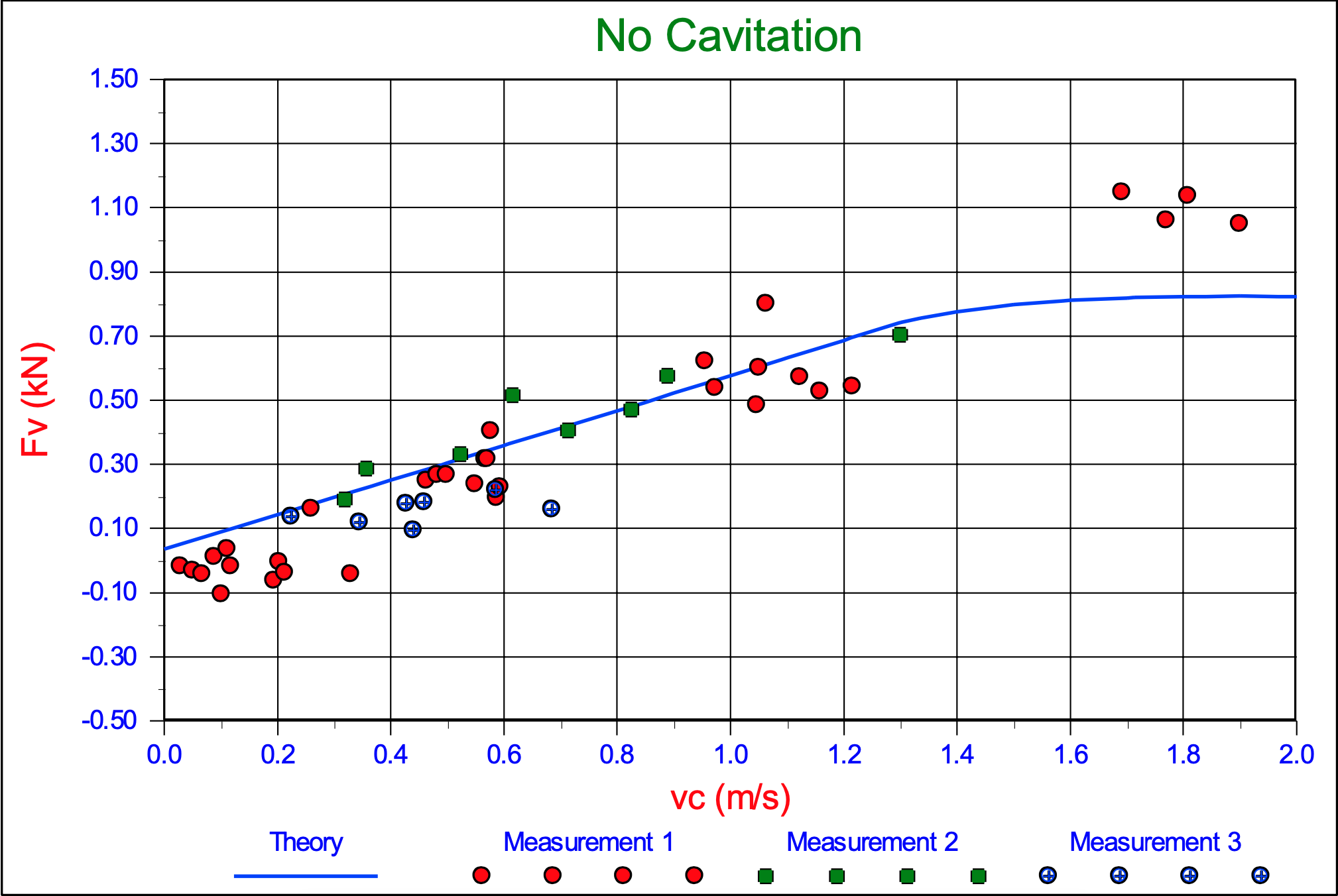
The cutting forces Fh and Fv on the blade. Experiments in 200 μm sand, with α=45°, β=30°, φ=38°, δ=30°, ni=38.53%, nmax=43.88%, ki=0.000165 m/s, kmax=0.000320 m/s, hi=70 mm, hb=141 mm, w=0.2 m, z=0.6 m and a non-cavitating cutting process.
The cutting forces Fh and Fv on the blade. Experiments in 200 μm sand, with α=45°, β=30°, φ=38°, δ=30°, ni=38.53%, nmax=43.88%, ki=0.000165 m/s, kmax=0.000320 m/s, hi=141 mm, hb=141 mm, w=0.2 m, z=0.6 m and a non-cavitating cutting process.
The cutting forces Fh and Fv on the blade. Experiments in 200 μm sand, with α=45°, β=30o, φ=38o, δ=30o, ni=38.53%, nmax=43.88%, ki=0.000165 m/s, kmax=0.000320 m/s, hi=58 mm, hb=173 mm, w=0.2 m, z=0.6 m and a non-cavitating cutting process.
The cutting forces Fh and Fv on the blade. Experiments in 200 μm sand, with α=45°, β=30°, φ=38°, δ=30°, ni=38.53%, nmax=43.88%, ki=0.000165 m/s, kmax=0.000320 m/s, hi=87 mm, hb=173 mm, w=0.2 m, z=0.6 m and a non-cavitating cutting process.
The cutting forces Fh and Fv on the blade. Experiments in 200 μm sand, with α=45°, β=30°, φ=38°, δ=30°, ni=38.53%, nmax=43.88%, ki=0.000165 m/s, kmax=0.000320 m/s, hi=173 mm, hb=173 mm, w=0.2 m, z=0.6 m and a non-cavitating cutting process.