Engineering LibreTexts

17.19: Appendix S- FEM Calculations with Wedge

  • Page ID
    36520
  • \( \newcommand{\vecs}[1]{\overset { \scriptstyle \rightharpoonup} {\mathbf{#1}} } \) \( \newcommand{\vecd}[1]{\overset{-\!-\!\rightharpoonup}{\vphantom{a}\smash {#1}}} \)\(\newcommand{\id}{\mathrm{id}}\) \( \newcommand{\Span}{\mathrm{span}}\) \( \newcommand{\kernel}{\mathrm{null}\,}\) \( \newcommand{\range}{\mathrm{range}\,}\) \( \newcommand{\RealPart}{\mathrm{Re}}\) \( \newcommand{\ImaginaryPart}{\mathrm{Im}}\) \( \newcommand{\Argument}{\mathrm{Arg}}\) \( \newcommand{\norm}[1]{\| #1 \|}\) \( \newcommand{\inner}[2]{\langle #1, #2 \rangle}\) \( \newcommand{\Span}{\mathrm{span}}\) \(\newcommand{\id}{\mathrm{id}}\) \( \newcommand{\Span}{\mathrm{span}}\) \( \newcommand{\kernel}{\mathrm{null}\,}\) \( \newcommand{\range}{\mathrm{range}\,}\) \( \newcommand{\RealPart}{\mathrm{Re}}\) \( \newcommand{\ImaginaryPart}{\mathrm{Im}}\) \( \newcommand{\Argument}{\mathrm{Arg}}\) \( \newcommand{\norm}[1]{\| #1 \|}\) \( \newcommand{\inner}[2]{\langle #1, #2 \rangle}\) \( \newcommand{\Span}{\mathrm{span}}\)\(\newcommand{\AA}{\unicode[.8,0]{x212B}}\)

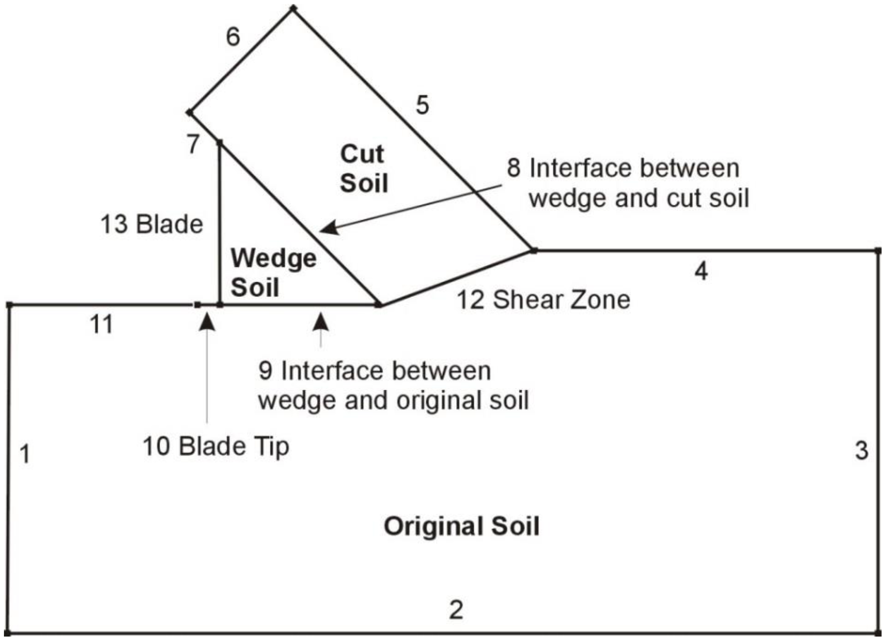
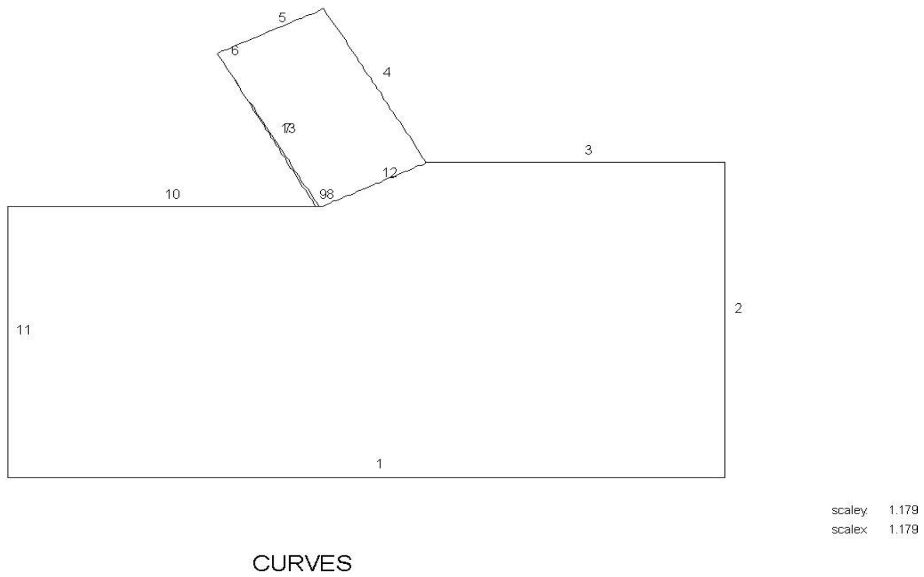
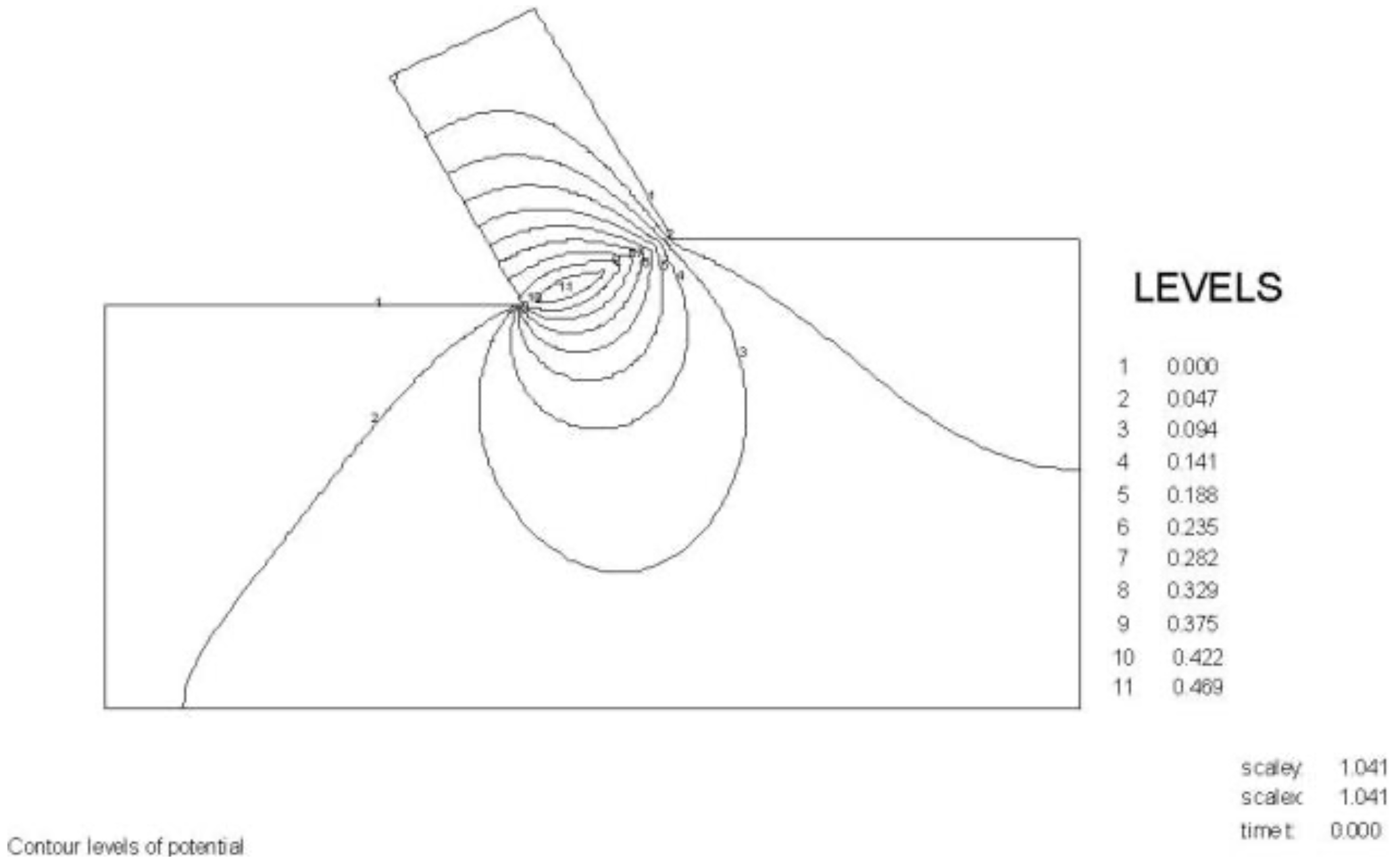
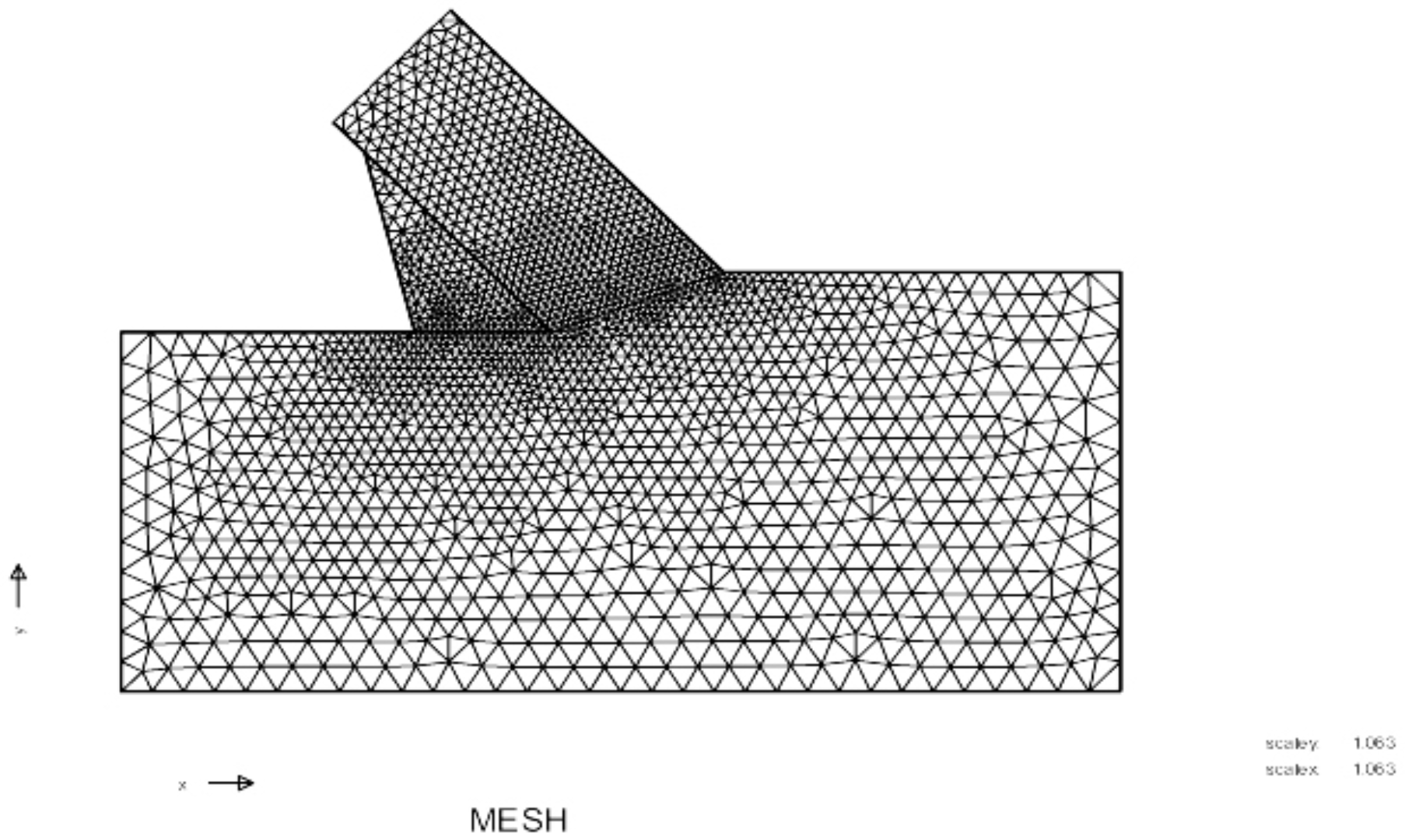
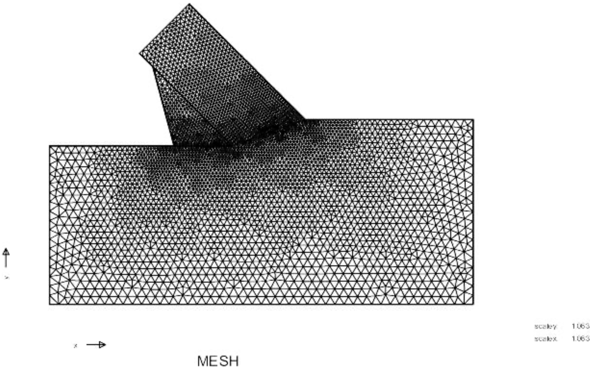
    S.1 The Boundaries of the FEM Model

    Screen Shot 2020-09-03 at 11.28.33 PM.png
    Figure S-1: The boundaries of the FEM model.
    Screen Shot 2020-09-03 at 11.29.29 PM.png
    Figure S-2: The boundaries of the 60/59 degree calculations.

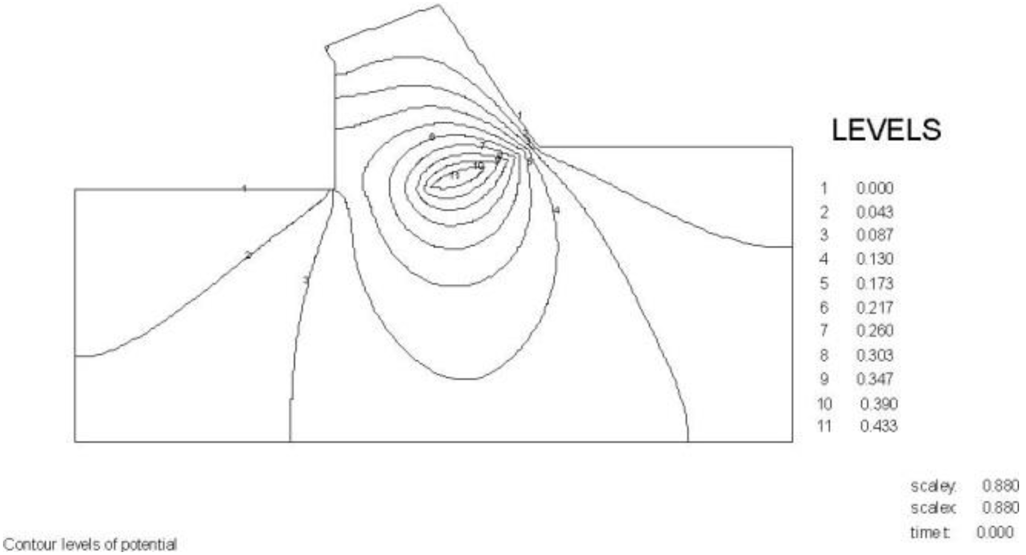
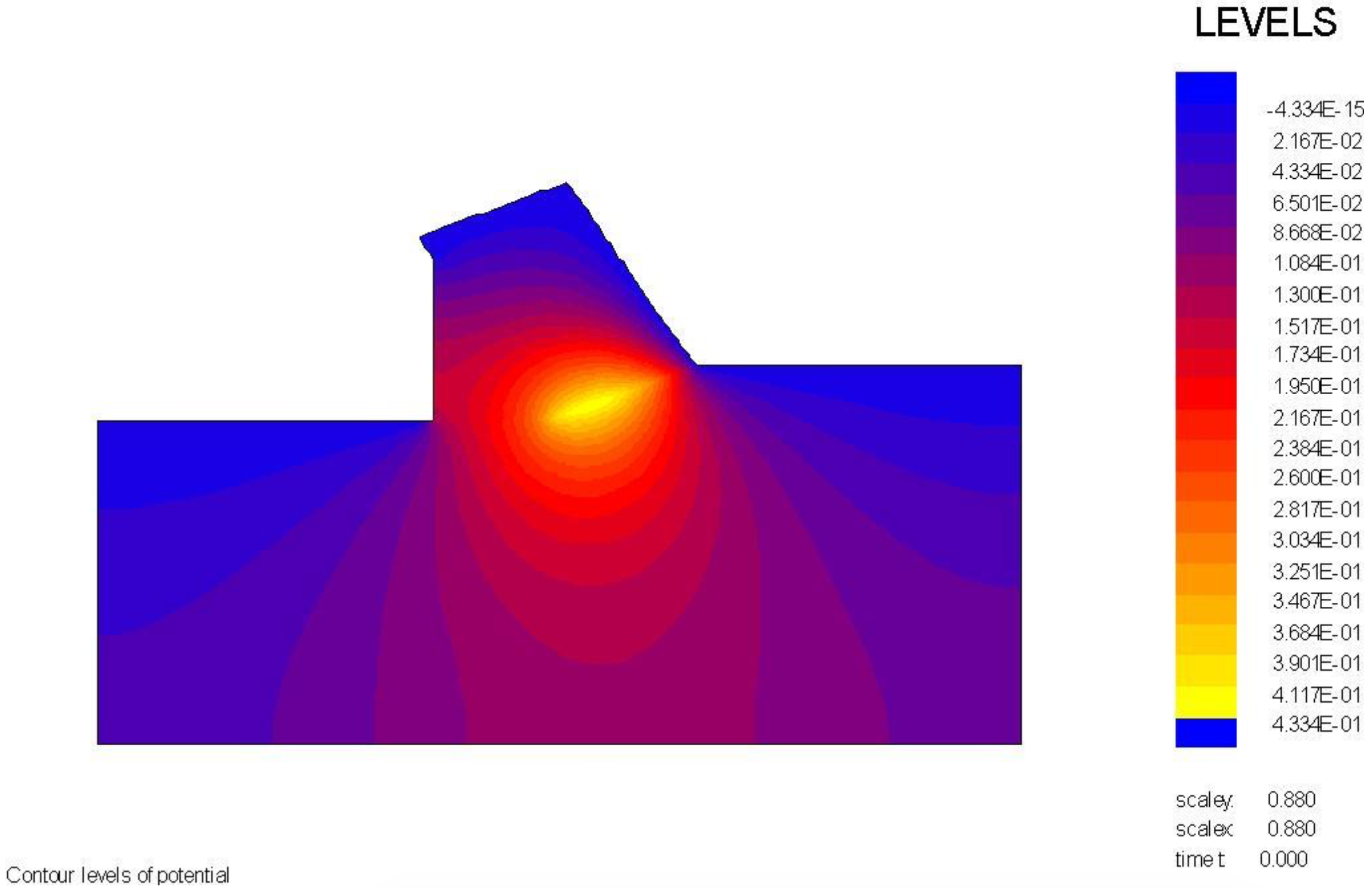
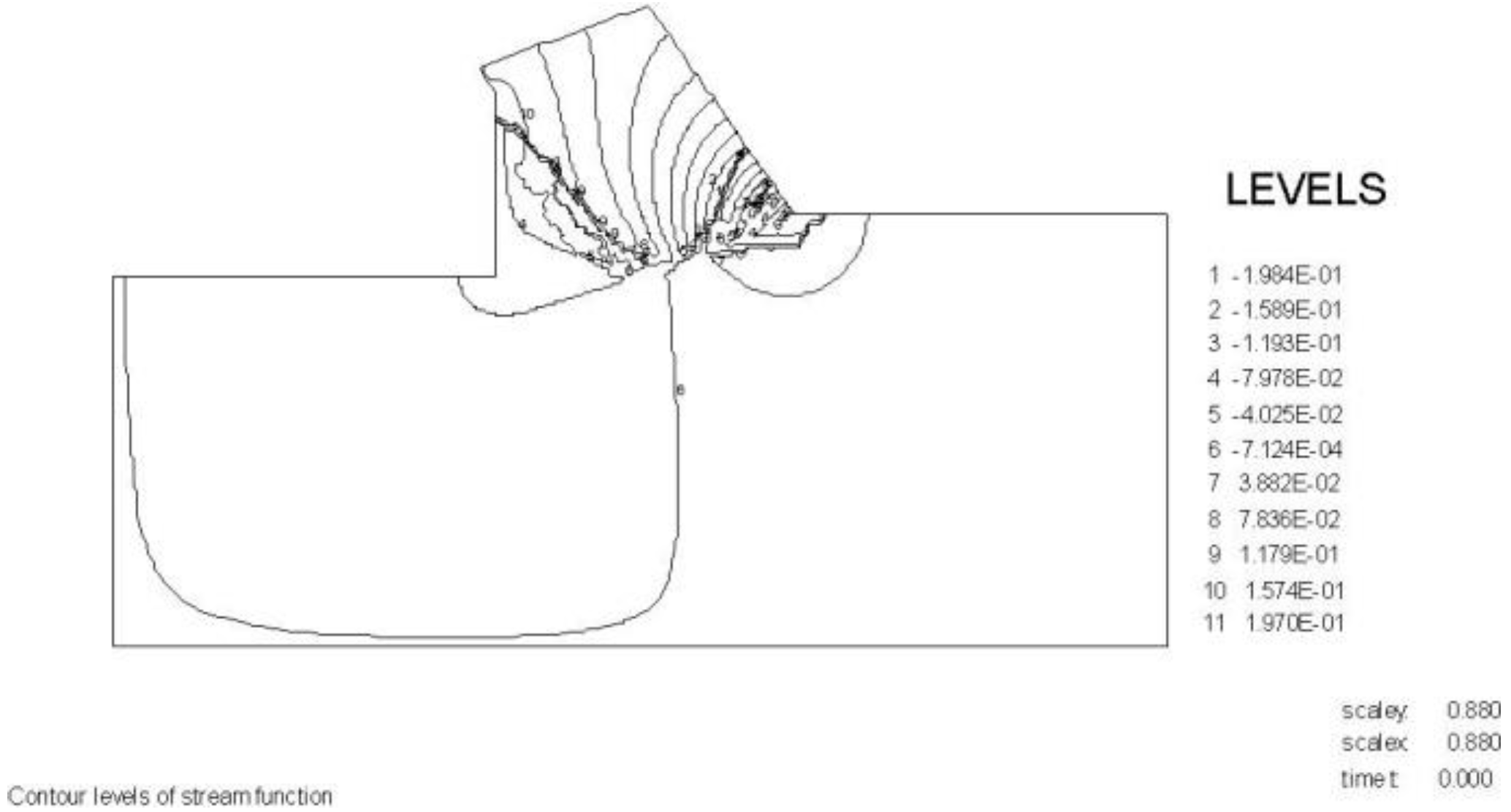
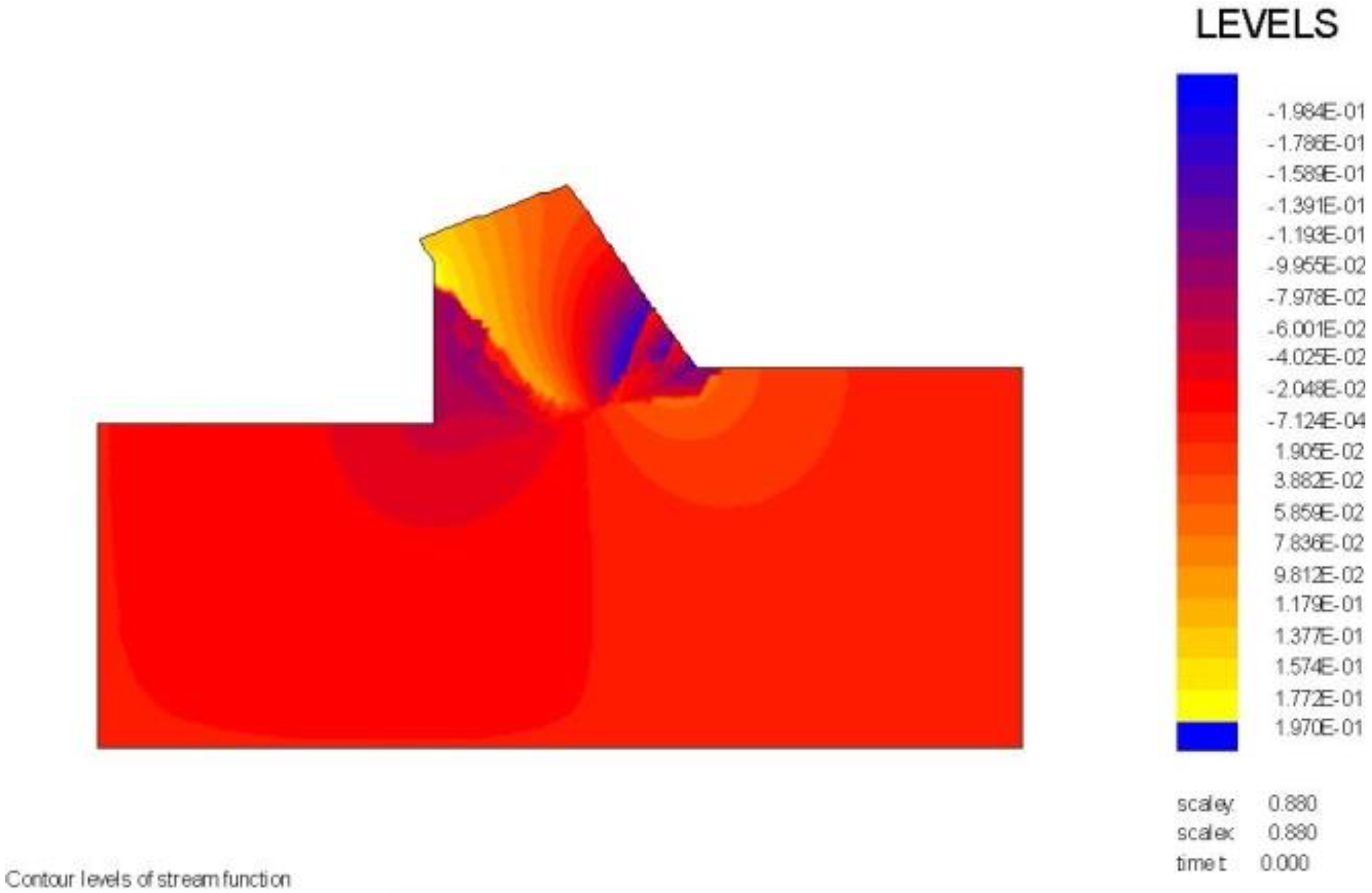
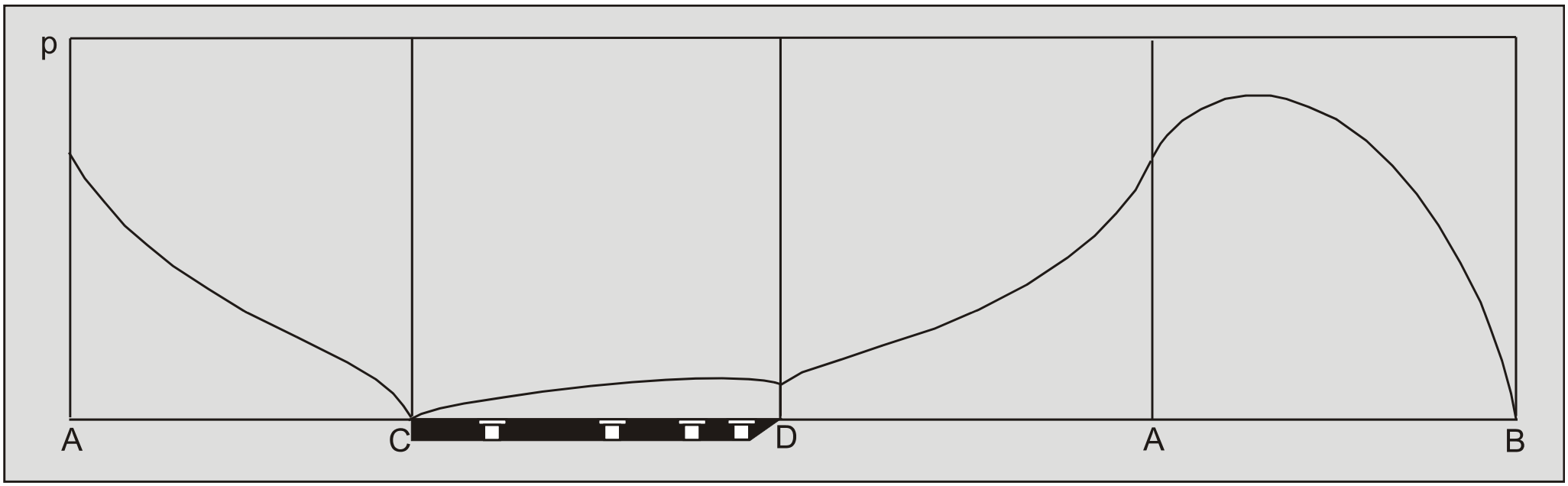
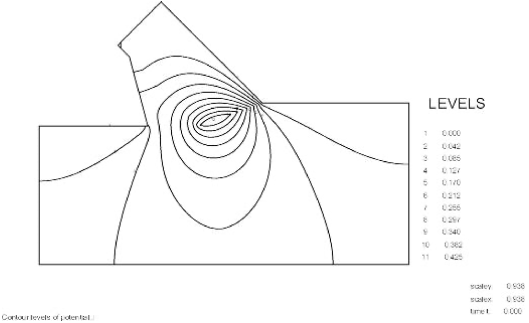
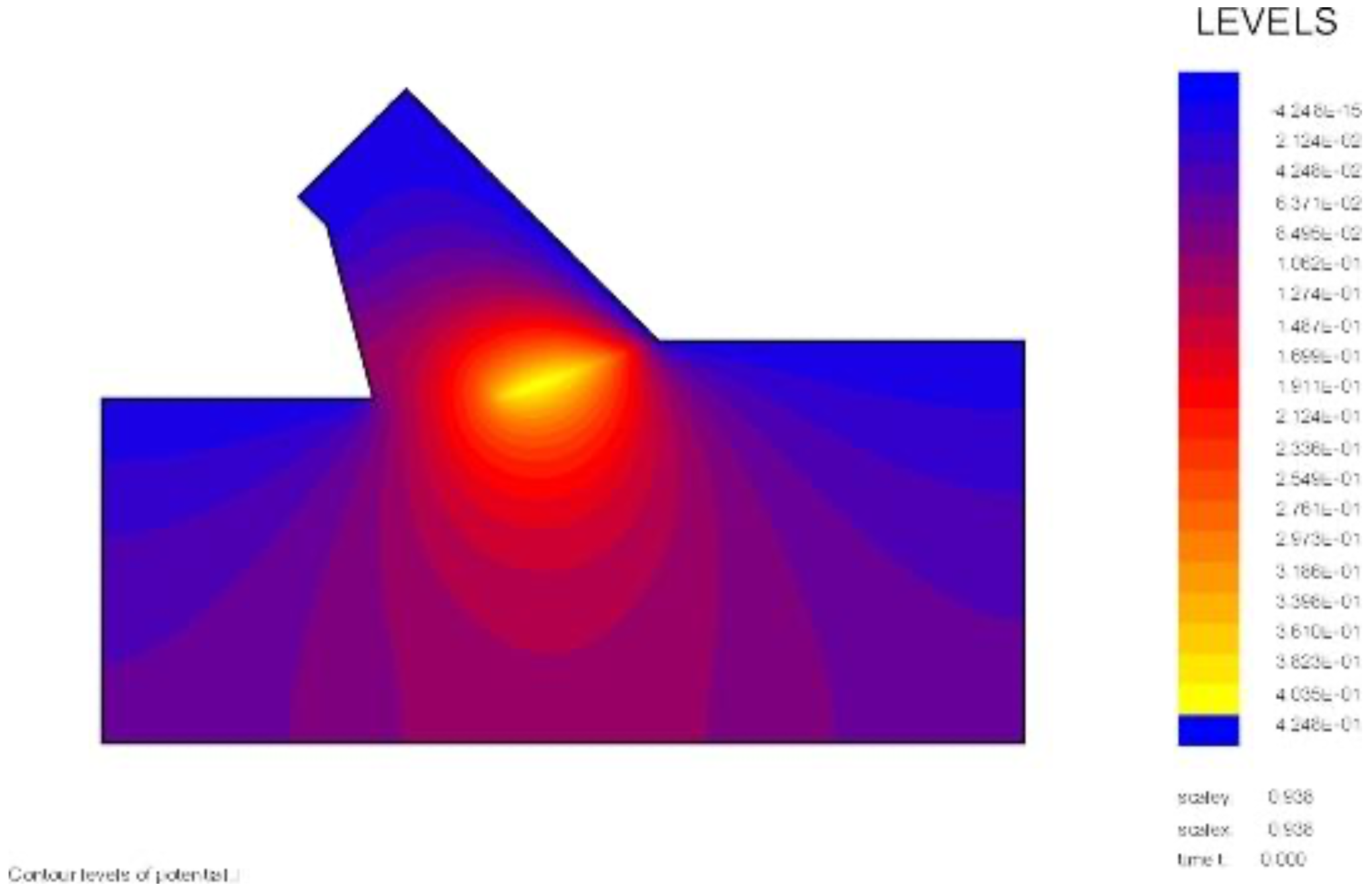
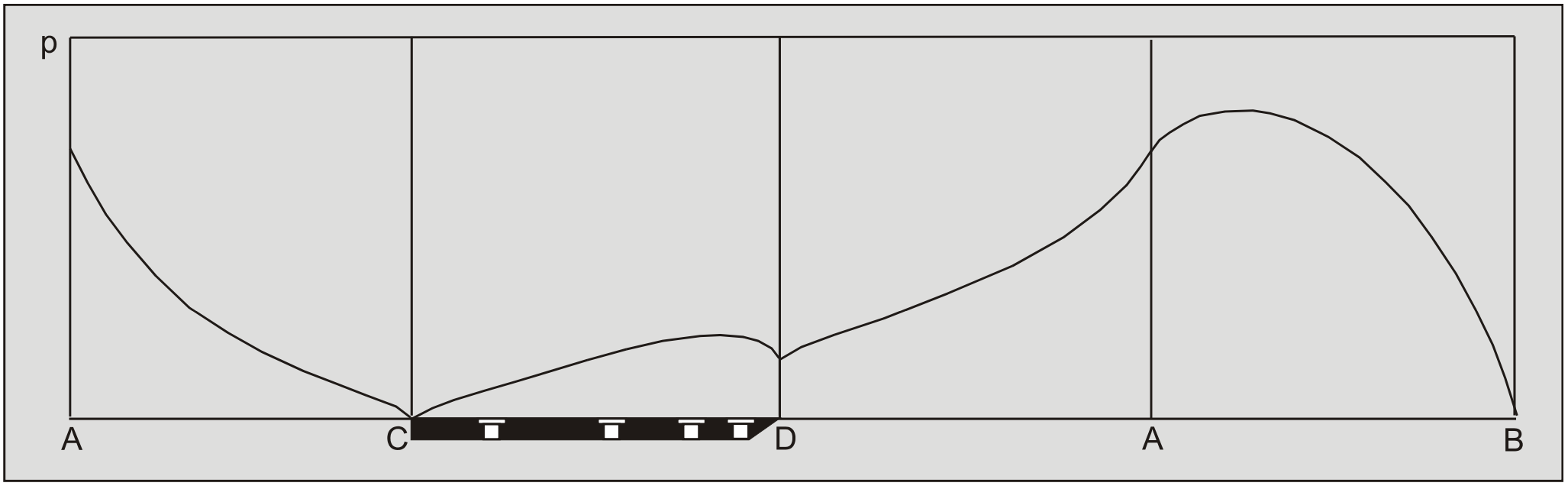
    S.2 The 60 Degree Blade

    Screen Shot 2020-09-03 at 11.31.09 PM.png
    Figure S-3: The equipotential lines.
    Screen Shot 2020-09-03 at 11.32.11 PM.png
    Figure S-4: The equipotential lines in color.
    Screen Shot 2020-09-03 at 11.34.00 PM.png
    Figure S-5: The flow lines or stream function.
    Screen Shot 2020-09-03 at 11.35.27 PM.png
    Figure S-6: The stream function in colors.
    Screen Shot 2020-09-03 at 11.36.28 PM.png
    Figure S-7: The pore pressures in the shear zone A-B, at the bottom of the wedge A-D, on the front of the wedge C-A and on the blade C-D

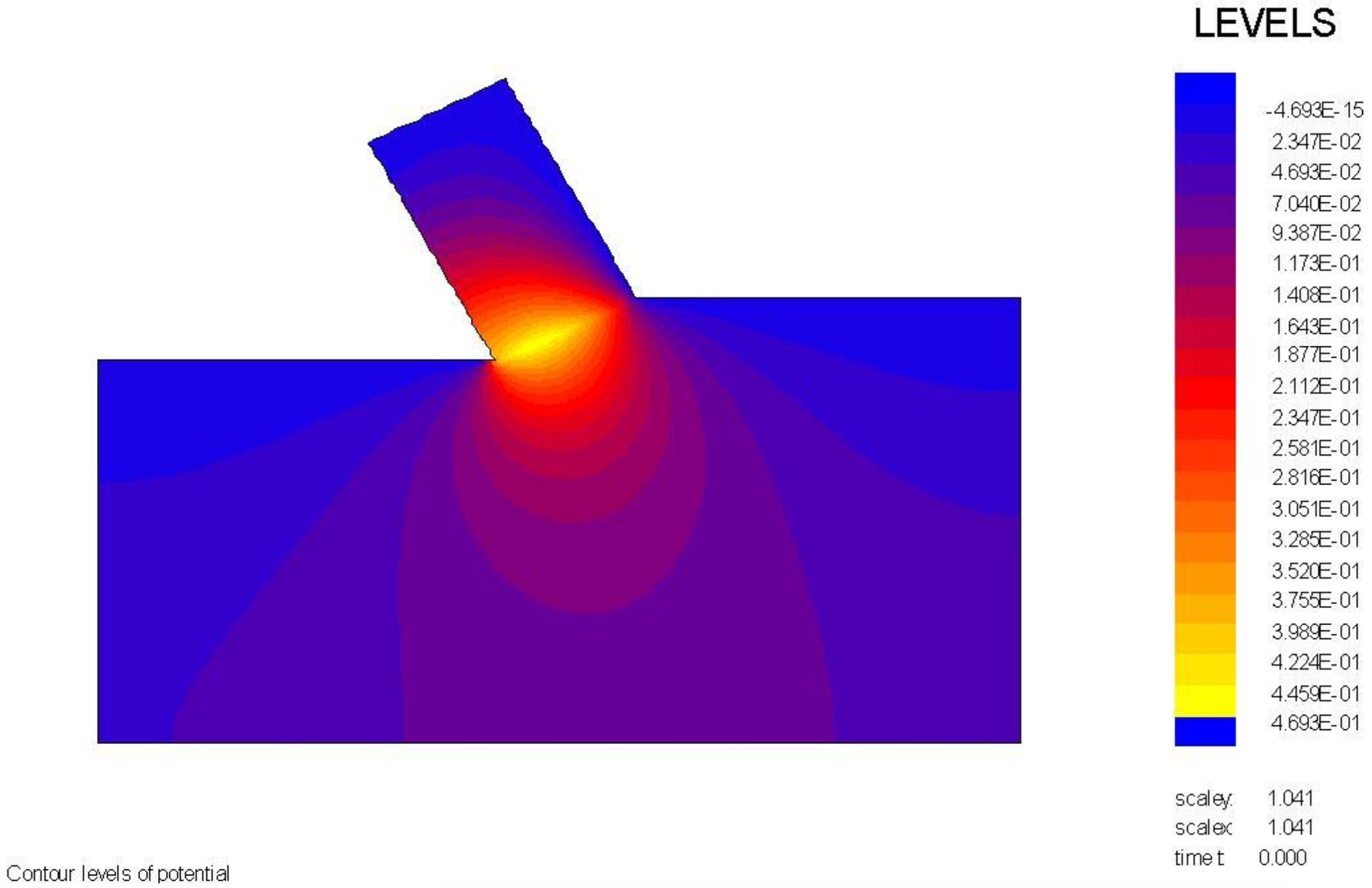
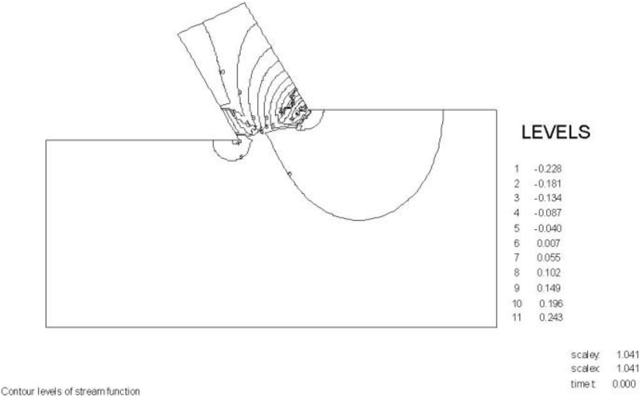
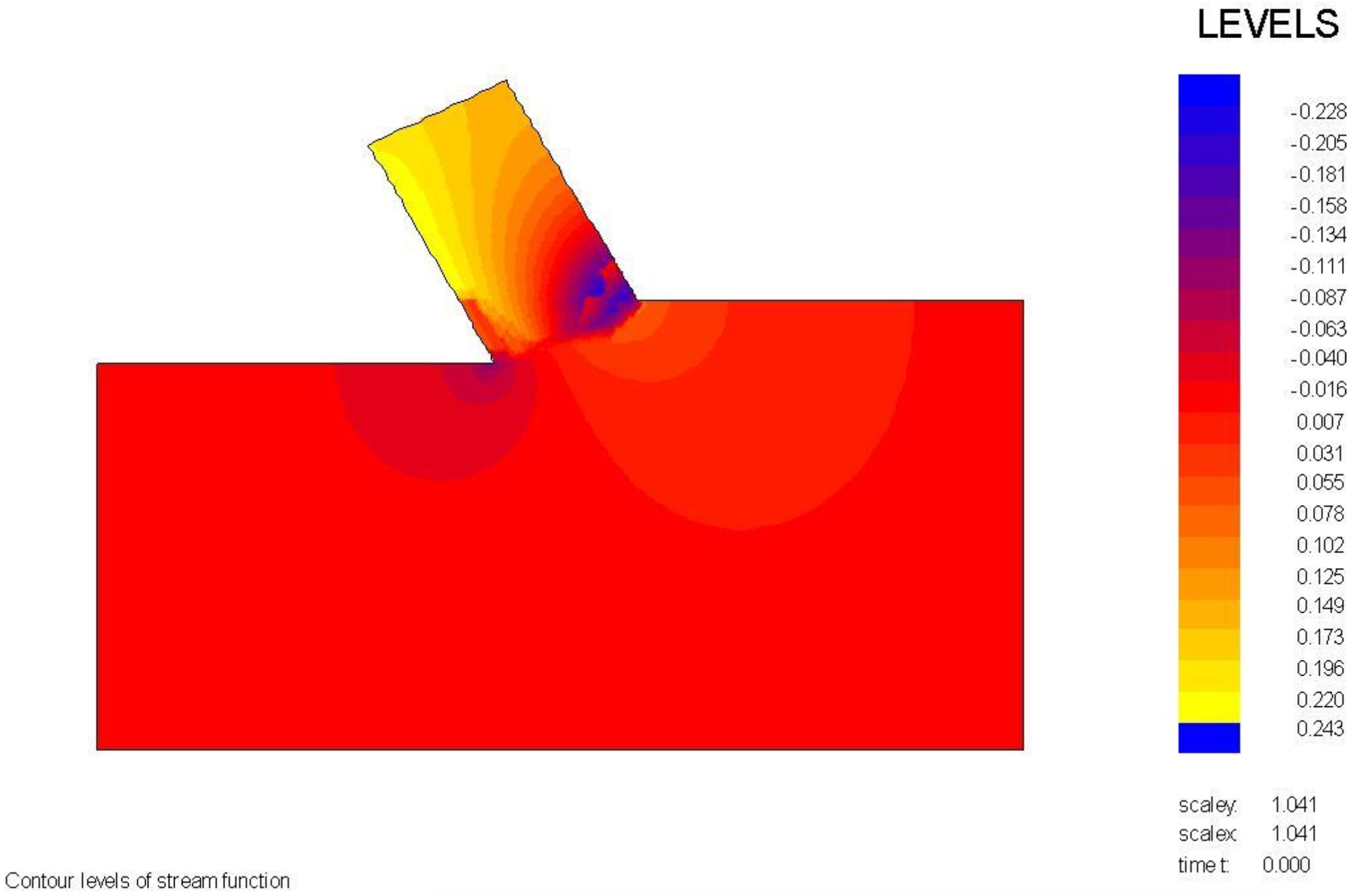
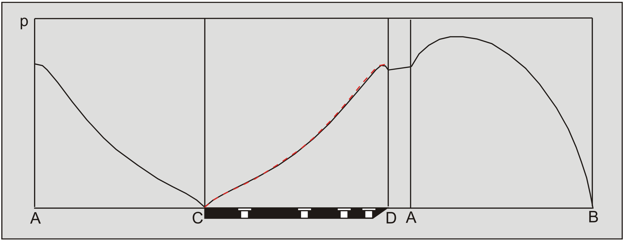
    The wedge angle in these calculations is 59 degrees. The pore pressures on the blade C-D are almost equal to the pore pressures on the front of the wedge A-C, which they should be with a blade angle of 60 degrees and a wedge angle of 59 degrees. The pore pressures on the front of the wedge C-A are drawn in red on top of the pore pressures on the blade C-A and match almost exactly.

    S.3 The 75 Degree Blade

    Screen Shot 2020-09-03 at 11.39.05 PM.png
    Figure S-8: The coarse mesh.
    Screen Shot 2020-09-03 at 11.39.55 PM.png
    Figure S-9: The fine mesh.
    Screen Shot 2020-09-03 at 11.41.04 PM.png
    Figure S-10: The equipotential lines.
    Screen Shot 2020-09-03 at 11.41.53 PM.png
    Figure S-11: The equipotential lines in color.
    Screen Shot 2020-09-03 at 11.42.41 PM.png
    Figure S-12: Pore pressure distribution on the shear plane A-B, the bottom of the wedge A-D, the blade D-C and the front of the wedge A-C.

    S.4 The 90 Degree Blade

    Screen Shot 2020-09-03 at 11.43.48 PM.png
    Figure S-13: Equipotential lines of pore pressures.
    Screen Shot 2020-09-03 at 11.46.37 PM.png
    Figure S-14: Equipotential distribution in color.
    Screen Shot 2020-09-03 at 11.50.50 PM.png
    Figure S-15: The flow lines or stream function.
    Screen Shot 2020-09-03 at 11.51.38 PM.png
    Figure S-16: The stream function in colors.
    Screen Shot 2020-09-03 at 11.52.27 PM.png
    Figure S-17: Pore pressure distribution on the shear plane A-B, the bottom of the wedge A-D, the blade D-C and the front of the wedge A-C.

    17.19: Appendix S- FEM Calculations with Wedge is shared under a not declared license and was authored, remixed, and/or curated by LibreTexts.

    • Was this article helpful?