
10.1: Blender Basics
- Page ID
- 14090

Blender has a unique interface, which is consistent across Windows, MacOS, and Linux. It works best with a fairly large display and a three-button mouse. A numeric keypad is also useful. The scroll wheel on most mice works as the third mouse button. If you are using an Apple mouse, you have to turn on multibutton support in the mouse preferences settings. Blender can be configured to emulate a middle mouse button using the combination of left mouse button with the ALT or Option key; this feature can be turned on in the “Input” section of Blender’s “User Preferences”, in the “File” menu.
This section discusses how fundamental aspects of 3D graphics concepts work in Blender, including geometric objects, transformations, light, material, and textures. See Section 1.2 for a basic introduction to these concepts, if you have not already read the relevant chapters of the book.
The 3D View
The Blender window is divided into non-overlapping sections, which are called “frames” but are sometimes referred to as “windows” even though they are really just panes in a window. The frames can contain in turn contains smaller sections that I will refer to as “panels.” The layout is very customizable.
If you have not customized the layout, the central frame of the window is a large “3D View” frame that shows a view of the 3D scene that you are working on. At startup, it contains a simple default scene. Here’s what it looks like, much reduced from its typical size, with annotations on some of its contents:
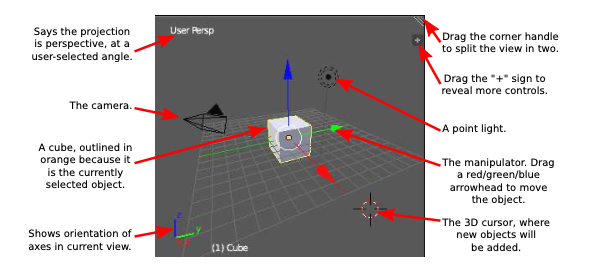
The 3D View frame also includes a Tools panel along the left edge and a narrow header panel along the bottom.
The only thing in the 3D view that will be visible in the rendered scene is the cube. The camera represents the point of view from which the image will be made. The point light provides illumination for the scene. The other things in the 3D View are there to help you edit the scene or to help you to understand what you are seeing. The grid lies in the xy-plane. The manipulator lets you transform the object. The 3D cursor marks a point in 3D space that is used for several editing operations. Note the plus sign, which reveals another panel of controls; to hide such a panel, drag its boundary to the edge of the frame. Note the triangle in the upper right. If you drag the triangle, the frame is split into two frames. You can remove a frame by joining it with its neighbor: Right-click the boundary between the two frames, select “Join” from the pop-up menu, and click the frame that you want to discard.
The 3D View window shows you a two-dimensional projection of a three-dimensional world. You need to be able to change the view, to look at the world from a different viewpoint. This can be done using the mouse or using the keys on the numeric keypad or “numpad”. (The numpad, if you have one, is the group of keys to the right of the keyboard. If you don’t have a numeric keypad, you can find equivalent commands in the “View” menu in the header panel at the bottom of the 3D View.)
Important Note
In Blender, key presses are sent to the frame that contains the mouse cursor. This does not follow standard GUI practice. It means that the mouse cursor must be in the 3D View for key presses to be sent to that frame. When pressing a key doesn’t seem to do anything, check the position of the mouse cursor!
To change the view with the mouse, use the middle mouse button. Drag with the middle mouse button to rotate the view. Hold the shift key down while dragging to translate the view (that is, move it up/down and left/right). Hold the control key down while dragging to zoom the view; move the mouse up to zoom in, or down to zoom out. You can also zoom in and out with the scroll-wheel feature of the mouse.
The numpad, or equivalent commands in the “View” menu, can be also be used to modify and zoom the view. But more important, they can be used to select certain common viewpoints. The initial view in the 3D View frame is a perspective projection of the world from a point that lies off all three coordinate axes. For working on the world, however, it’s generally better to use an orthographic projection. Use the “5” key on the numpad to switch between projection types. Use the numpad “1”, “3”, and “7” keys to select projections onto the xz, yz, and xy planes. These are probably the most useful views for modeling, and checking out the world. Using all three projections can give you a good idea of the 3D positions of the objects in the scene. The camera view (Numpad “0”) is also very useful for modeling. Here’s a list of all the numpad commands:
- Numpad 0 — View from the camera. Hit Numpad 0 again to return to the previous user view. The camera view is important because it’s what you will see when you render an image.
- Numpad 1 — View from “front,” perpendicular to the xz-plane.
- Numpad 3 — View from “side,” perpendicular to the yz-plane.
- Numpad 7 — View from “top,” perpendicular to the xy-plane.
- Numpad 5 — Toggles between orthographic and perspective projection.
- Numpad 2,4,6,8 — Rotate the view.
- Numpad +,- — Zoom in and out.
- Numpad . — Zoom to show the selected object or objects. (The “Home” key will bring
- all objects into view.)
- Numpad / — Show only the selected object or objects. Hit Numpad-/ again to return to the full view. This feature is very useful when editing an object.
Adding and Transforming Objects
Changing the view does not modify the contents of the world. To do that, you need editing operations such as adding objects to the world. This is where the 3D cursor comes in. The 3D cursor is labeled in the above image of the 3D View frame. A newly added object is always added to the world at the position of the 3D cursor.
You must position the 3D cursor before adding the object. The 3D cursor is positioned by clicking on the 3D View window with the left mouse button. The 3D cursor exists in three- dimensional space. You can’t tell where it is by looking at the world from just one point of view. Typically, you would check the position of the 3D cursor from several viewpoints by rotating the view or by using the Keypad 1, 3, and 7 keys to switch between views.
Another way to position the 3D cursor is with the “Snap” menu, which you can call up by pressing SHIFT-S while the mouse cursor is in the 3D Vew window. (Remember that the cursor must be in the 3D View frame for keystrokes to be sent to that frame.) You can also find the Snap menu as a submenu in the “Object” menu below the 3D View. This menu contains commands for positioning the cursor as well as for positioning objects. For example, use “Cursor To Center” to move the 3D cursor to the point (0,0,0).
Once you have the 3D cursor in position, use the “Add” menu to add an object to the world. You can pop up the Add menu at the mouse position by hitting Shift-A, or you can find it in the header panel below the 3D View. The Add menu has submenus for adding several types of objects. I suggest that you stick with mesh objects at first. (A mesh is a surface made up of polygons or a curve made up of line segments.) Various mesh objects are available in the “Mesh” submenu of the Add menu. For example, A UVSphere is a sphere divided into segments by lines of latitude and longitude. An ICOSphere is divided into triangles. A Plane is actually just a rectangle. (When you first start Blender, the object in the default scene is a mesh Cube.)
When adding certain types of objects, there are some options you can change. When you add the object, a panel containing these options appears in the lower left region of the 3D View frame. The following image shows part of that panel for a Mesh UVSphere. You can change the number of Segments and Rings, which are the number of subdivisions around the equator of the sphere and the number from the north pole to the south pole.
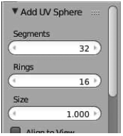
The numerical input widgets in this panel are examples of Blender’s funny input buttons. Here’s how to use such buttons: You can click the button, type in a value, and press return. You can click the arrows at the ends of the button to increase/decrease the value. Or you can drag the mouse left-to-right or right-to-left on the button to change the value.
Objects can be “selected.” When you apply an edit operation to the 3D View window, it affects the selected object or objects. When you add an object to the scene, the new object is automatically selected. You can select an object by right-clicking it. Selected objects are shown outlined in orange. You can select multiple objects by holding down the Shift key as you right-click the objects. When multiple objects are selected, certain operations only apply to the most recently selected object. That object is shown in a slightly brighter orange. A manipulator, shown in the image at the beginning of this section, appears at the selected object or at the center of the group of selected objects. You can move the selected object or objects in the direction of the coordinate axes by dragging the arrow heads on the manipulator axes. You can change the manipulator to one that can be used for rotation or scaling instead of translation. Look for the manipulator controls below the 3D View:
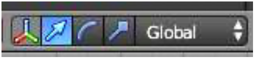
Clicking the icon on the left end of this group of controls will toggle the visibility of the manipulator. The next three icons select the type of manipulator.
To delete the selected object or objects, just hit the X key or the Delete key. You will be asked to confirm the deletion. (Remember that the mouse cursor must be in the 3D window for it to get keyboard commands. (This is the last time I will say this.))
As you modify the world, you can undo most operations by pressing Control-Z. That includes adding, deleting, and editing objects. Conrol-Shift-Z is the Redo operation.
There are other, more general ways to transform objects using the keyboard and mouse instead of the manipulator. Note that you do not simply click-and-drag an object to move it! Instead, select the object or objects you want to transform by right-clicking them, then apply the transformation as follows:
- Press the “G” key. (G stands for “grab”.) Move the mouse without holding down any button. You can move the object in the plane of the screen only. Click with the left mouse button to finish. Click with the right mouse button to abort. (Hitting return will also finish; hitting Escape will also abort.) After hitting the “G” key, you can hit “X”, “Y”, or “Z” to constrain motion to one axis. (Alternatively, you can start moving an object if you just right-click and start dragging. However, releasing the right-mouse does not end the move! You still have to end it as described here.)
- Press the “S” key. Without holding down any mouse key, move the mouse towards or away from the object to change its size. The size changes in all three dimensions. Click with the left mouse button to finish. Click with the right mouse button to abort. After hitting “S”, you can hit “X”, “Y”, or “Z” to scale the object in the direction of one axis only.
- Press the “R” key. Without holding down any mouse key, move the mouse to rotate the object around a line perpendicular to the screen. Click with the left mouse button to finish. Click with the right mouse button to abort. If you hit “R” a second time, you can freely rotate the object. After hitting “R”, you can hit “X”, “Y”, or “Z” to rotate the object about the specified axis.
Whether rotating, scaling, or translating, you can hold the Control key down to limit the changes, such as to integral amounts while translating or to multiples of ten degrees while rotating. Also, you can use the arrow keys to make small adjustments.
You can get yourself real confused if you don’t remember to press the left or right mouse button to complete a transformation operation. You can’t do anything else until the operation is completed.
All these operations can be applied to the camera, just as they are applied to any other object. You can move and point the camera to get the view of the world that you want to see when you render an image. You can even apply transformations to the camera while in the camera view (Numpad 0), as long as the camera is the selected object. This can be a good way to get the exact view that you want for an image.
Note that rotations and scaling are relative to the “center” of the selected object or group of objects, the point where the manipulator is drawn. This center point is not necessarily at the geometric center of the object.
Edit Mode
Ordinary transformations (and many other operations) are applied to an object as a whole. Sometimes, however, you want to work on the vertices, edges, or faces of an object. For that, you use “edit mode.”
To enter Edit Mode for the selected object, press TAB. When in Edit Mode, press TAB to exit Edit Mode. In Edit Mode, you can select individual vertices and groups of vertices. You can select a face by selecting all the vertices of that face. You can select an edge by selecting both vertices of that edge. You can scale, rotate, and translate selected elements in the usual way, with the S, R, and G keys, or using the manipulator. You can delete things with the X key. Hitting the W key will pop up a large menu of actions that you can take on the selected elements.
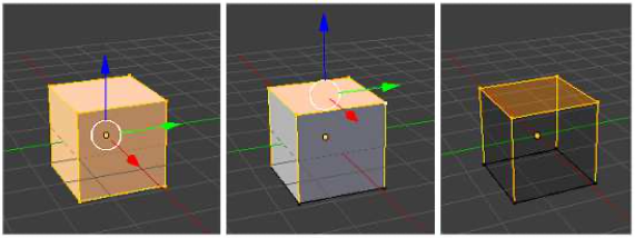
In Edit Mode, selected vertices and faces are orange. The picture on the left below shows a cube in edit mode with all vertices selected. In the second picture, only the vertices of the top face are selected. In can be easier to work in Edit Mode using a “wireframe” view instead of the default “solid” view. Hit the “Z” key to toggle between the two views. The third picture shows the cube as a wireframe, with the manipulator hidden to make it even easier to see what you are doing.
When you first enter Edit Mode for a mesh object, all of its vertices are selected. Pressing the “A” key will deselect all vertices. If you press the “A” key when no vertices are selected, all the vertices will be selected. You can select a vertex by right-clicking near it. Hold down the shift key while right-clicking to select multiple vertices. Shift-right-click a selected vertex to de-select it. There is a way to add a several vertices to the selection at the same time: Hit the “B” key. You can then draw a “box” by left-clicking and dragging with the mouse. Vertices within the box when you release the mouse button are added to the set of selected vertices. This is an easy way, for example, to select all the vertices at the top of a cube. (It can be easier to select sets of vertices in wireframe mode.) You might have to change the point of view several times while selecting the vertices and performing operations on them.
There are a lot of things you can’t do in Edit Mode, so don’t forget that you have to press the TAB key to get out of that mode!
By the way, the “Z” key can be used outside of Edit Mode to toggle between a solid and a wireframe view of the selected object. And the “A” and “B” keys can be used outside of Edit Mode for selecting sets of objects. If you get lost in the 3D view, use the A key to select all objects, then hit Numpad-period; this will bring all objects into view.
Light, Material, and Texture
Lights in a scene don’t affect the appearance of objects in the 3D View. Lighting is used only when an image of the scene is rendered. If there are no lights in the scene, then no objects will be visible in the rendered image.
There is already one light in the default scene, which you can drag around so that it best illuminates your objects. An easy way to be sure of lighting all visible objects is to place the light at the position of the camera. You can add additional lights, using the “Lamp” submenu in the “Add” menu. “Lamp” is Blender’s term for “light.” As for any object, a new lamp appears at the position of the 3D cursor. You might have to add several lamps to light your scene well.
There are several kinds of lamp in the “Lamp” submenu. A “Point” lamp gives off light in all directions. The light in the initial scene is a point lamp. A “Sun” means light shining in parallel rays from some direction, indicated by a line drawn from the lamp in the 3D view. A “Spot” is a spotlight that gives off a cone of light. You need to aim a sun or spotlight at the objects you want to illuminate. Change the direction of a sun or spot by rotating it.
The default color of an object is gray. To change this, you have to add a “material” to the object and set the properties of that material. (The cube in the start-up world has a material; new objects that you add don’t.) To work on materials, use the Properties Editor frame, which you can find to the right of the 3D view. That frame allows you to set all kinds of properties of objects. At the top of the frame there is a a row of buttons that select which group of properties you want to work on. The buttons that appear in this row depend on what kind of object is currently selected, although some are always present. Here are the buttons that are shown when the selected object is a mesh. You might have to expand the width of the frame to see them all in the Blender window:
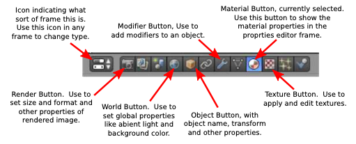
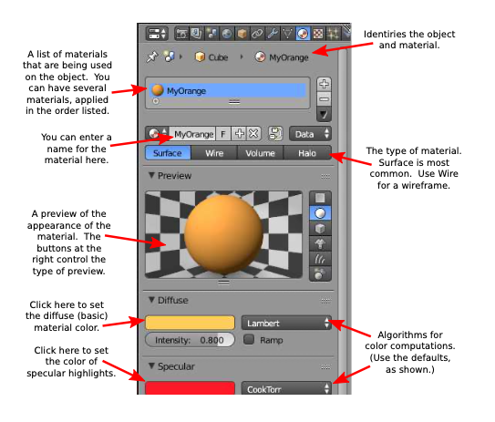
In this picture, the Materials button has been clicked. With the materials button selected, the rest of the editor panel, below the header, is filled with controls for setting the material properties of the selected object. Most of the controls don’t appear until a material has been added to the object. If there is no material, you will see a “New” button in the properties frame. (The Properties Editor view can look empty because its contents have been scrolled out of sight. If you don’t see anything, check the scrollbar!) Click the “New” button to add a new material to the object, or click the icon to the left of “New” to use a material that already exists. The full set of controls will appear. Here’s what you will see in the top part of the frame:
A texture makes the color or some other property of an object vary from point to point. One type of texture copies colors from an image, effectively painting the image on the surface of the object. This is called an image texture. Alternatively, the color can be computed algorithmically from the coordinates of the point. This is called a procedural texture.
A texture should only be added to an object that already has a material, since texture is considered to be part of the material. To add a texture to an object, select the object (and add a material if it doesn’t already have one!). Click on the texture button in the header of the Properties Editor frame. If the object already has a texture, you will be able to edit it. Otherwise, click the “New” button, or select an existing texture from the list, just as for the material. Once you’ve added the texture, a “Type” popup menu will appear where you can choose the type of texture that you want to use.
One type of texture is an Image texture. If you choose that type, you will see an “Open” button that you can click to select the image file that you want to use as a texture.
Most of the remaining texture types are procedural textures. You might try “Marble”, “Clouds”, and “Wood”. When you select one of these, controls appear that allow you to modify the appearance of the texture. The Marble pattern, for example, usually looks better if it’s set to “Sharp” or “Sharper” rather than “Soft.” In general, you should set the “Coordinates” in the “Mapping” section of the Material controls to “Generated” to get the best effect.
The Clouds, Wood, and Marble textures make patterns of two colors. One color is the diffuse material color of the object. The other is set as a property of the texture (look for the color patch in the “Influence” section of the texture properties panel). By default, the second color is an ugly magenta, which you will want to change.
To see what the texture will look like on an object, go back to the material properties by clicking the Material button in the header.
Saving Your Work
The 3D window shows positions, sizes, and colors of your objects. To see a fully rendered scene from the point of view of the camera, hit the F12 key. To dismiss that view, hit Escape or F11. There are are also commands in the “Render” menu, at the top of the Blender menu, that do the same things. Many aspects of the scene, including textures, transparency, and shadows, do not appear in the 3D View window. To see them, you have to render an image.
When you render an image, the image is created but it is not saved anywhere. To save it, use the F3 key while the rendered image is on screen, or use the “Save as Image” command from the “Image” menu at the bottom of the frame where the rendered image is displayed. The size and default format of the image are set in the Properties Editor frame, with the “Render” button selected.
When you save an image—or need to choose a file from the file system for some other reason—you will see the Blender File Browser frame. The File Browser, like the rest of Blender, uses a non-standard interface. However, it is not difficult to use. You can browse the file system using the directory listing in the center of the frame. Click the top item in the list (shown as “..”) to go up one directory. Shortcuts to some directories are listed along the left edge of the frame. Two input fields at the top of the frame show the selected directory and file name. For saving a file, you should edit the file name by hand. Click the “Save” or “Cancel” button to the right of the input fields to finish.
To save your entire Blender session, use the “Save” command in the “File” menu. A Blender session is stored in a file with the extension “.blend”. Opening a .blend file will restore the saved state of the program. If you use the “Save Startup File” command in the “File” menu, Blender will save the current state of the program in a .blend file somewhere in your home directory. After that, when you start Blender, it will open that file as the starting point for your session, instead of the usual initial scene. This feature allows you customize your startup environment.
More Features
We have covered a lot of basic ground about Blender, but before looking at more advanced modeling and animation, there is a little more background information that will be useful ...
Duplicating; Data versus Object: An object on the screen has two aspects: The basic data for the object and the transform that has been applied to that data. The data for a mesh, for example, would be the coordinates of all its vertices in the mesh’s own coordinate system. It also includes the material properties of the mesh. It’s possible for objects to share the same data but have different transforms. Suppose you want to duplicate an object. There are two ways to do it. You can select the object and hit SHIFT-D. This will make a copy of the selected object. The copy will be in the exact same place as the original, but will be in “grab” mode so that you can immediately move it away from the original by moving the mouse. When you duplicate an object in this way, with SHIFT-D, you make copies of both the object and its data. That is, you really do get a complete copy. However, you can also duplicate the selected object by hitting ALT-D. When you use ALT-D, the two objects share the same data; only their transforms are different. This means that if you go into Edit Mode and change one of the object’s vertices, the same changes are applied to the other object. If you change the material on one of the objects, the other one changes as well. On the other hand, if you transform one of the objects by moving, scaling, or rotating it, the change does not affect the copy. This type of copy can actually be very useful—and it can save memory since there is only one copy of the object data.
Parenting: One object can be a “parent” of another. This allows you to create hierarchical models. When you drag, rotate, or scale a parent, all its child objects are transformed as a group along with the parent. But child objects can still have their own transformations within the group. Furthermore, a child of one object can be a parent of another object, so you can do multi-level hierarchical graphics. If you want to group several objects, and there is no obvious parent, you should consider parenting all the objects to an empty object, made with the “Empty” command in the “Add” menu. To create a parent relationship, select the child object or objects, then shift-right-click the parent to add it to the selection. Hit CONTROL-P. You will have to confirm that you want to make a parent. A dotted line will join the child to its parent in the 3D View. To delete a parent relationship, select the child, hit ALT-P, and select “Clear Parent” from the popup menu.
Smooth Shading: By default, mesh objects have a “faceted” appearance where the polygons that make up the mesh look flat. The effect is called flat shading. Sometimes this is correct, but often you want to use the mesh as an approximation for a smooth object, such as a sphere. In that case you want to use smooth shading instead. To select between flat shading and smooth shading for a mesh object, select the object and look in the “Tools” panel to the left of the 3D View. You’ll find two “Shading” buttons, marked “Flat” and “Smooth,” for selecting the type of shading. Setting a mesh object to use smooth shading does not change the geometry of the object; it just uses different normal vectors (see Subsection 4.1.3).
Layers: Blender has “layers”, where each layer can contain its own collection of objects. When several layers are shown in the 3D View, their objects are not actually layered on top of each other; all the objects from all the visible layers are shown intermingled in one 3D scene. The point is that you can show and hide objects by turning the layers that contain them on and off. The main point is to allow you to work on objects in one layer without being confused by the objects in the other layers. Blender has exactly 20 layers, and they are controlled by a set of 20 small buttons in the header panel at the bottom of the 3D View. The buttons look like this:
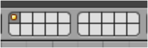
A dot in a layer button means that that layer contains one or more objects. Layers that are selected for viewing are shown in a darker gray. You can click a layer button to select just that layer. You can shift-click to select multiple layers. You can move objects from one layer to another: Select the object and hit the “M” key; a set of layer buttons will pop up where you can select the layer to which you want to move the object. You can use hidden layers to store objects that you have worked on, but that you don’t want to be visible at the moment.
Naming: In Blender, objects, textures, materials, scenes, etc., all have names. Blender automatically assigns generic names such as “Cube.002” when you create or duplicate an object. Sometimes, you need to know something’s name. An example is the “text on curve” feature that will be discussed in the next section. To make it easier to identify an object, you might want to use a more meaningful name. Names are generally displayed in editable boxes. You can just click the box and enter a new name. For objects, the name is displayed in the “Object” controls in the Properties Editor frame.
Scenes and Screens: A “scene” in Blender is its own 3D world. Each scene can contain unique objects, but it is also possible for scenes to share objects. There is a popup menu at the top of the Blender window that you can use to create new scenes and to switch from one scene to another. To its left is a popup menu for selecting a “screen.” A screen is a customized layout for the Blender window. The two menus look like this:

Click the icon at the left end of the control to pop up the menu. Click the center of the control to enter a new name for the current item. Click the “X” on the right end to delete the item. Click the “+” sign to create a new screen or scene. When you create a new screen, it is a duplicate of the current screen. When you create a new scene, you will get several options in a popup menu: “New” will create an empty scene. “Link Objects” will create a scene that contains the same objects as the current scene, with the same transforms; if you move an object in one scene, it also moves in the other one. You can then add new objects later that will be in only one of the scenes. You might use this, for example, if you want to set up a common static background world and then make several scenes that show different “actors” doing different things in different scenes, but with the same environment. With “Link Object Data”, objects in the two scenes share the same data but not the same transform; this lets you have the same actors doing different things in different scenes, with the same environment. “Full Copy” copies both the transforms and data, so the scenes look the same originally, but really have no shared data in common.