
2.8: Access Networks
- Page ID
- 13953
2.8 Access Networks
2.8 Access Networks
In addition to the Ethernet and Wi-Fi connections we typically use to connect to the Internet at home, at work, at school, and in many public spaces, most of us connect to the Internet over an access or broadband service that we buy from an ISP. This section describes two such technologies: Passive Optical Networks (PON), commonly referred to as fiber-to-the-home, and Cellular Networks that connect our mobile devices. In both cases, the networks are multi-access (like Ethernet and Wi-Fi), but as we will see, their approach to mediating access is quite different.
To set a little more context, ISPs (often a Telco or Cable company) often operate a national backbone, and connected to the periphery of that backbone are hundreds or thousands of edge sites, each of which serves a city or neighborhood. These edge sites are commonly called Central Offices in the Telco world and Head Ends in the cable world, but despite their names implying "centralized" and "root of the hierarchy" these sites are at the very edge of the ISP's network; the ISP-side of the last-mile that directly connects to customers. PON and Cellular access networks are anchored in these facilities.
DSL is the legacy, copper-based counterpart to PON. DSL links are also terminated in Telco Central Offices, but we do not describe this technology since it is being phased out.
Passive Optical Network
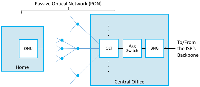
PON is the technology most commonly used to deliver fiber-based broadband to homes and businesses. PON adopts a point-to-multipoint design, which means the network is structured as a tree, with a single point starting in the ISP's network and then fanning out to reach up to 1024 homes. PON gets its name from the fact that the splitters are passive: they forward optical signals downstream and upstream without actively storing-and-forwarding frames. In this way, they are the optical variant of repeaters used in the classic Ethernet. Framing then happens at the source in the ISP's premises, in a device called an Optical Line Terminal (OLT), and at the end-points in individual homes, in a device called an Optical Network Unit (ONU).
Figure 1 shows an example PON, simplified to depict just one ONU and one OLT. In practice, a Central Office would include multiple OLTs connecting to thousands of customer homes. For completeness, Figure 1 also includes two other details about how the PON is connected to the ISP's backbone (and hence, to the rest of the Internet). The Agg Switch aggregates traffic from a set of OLTs, and the BNG (Broadband Network Gateway) is a piece of Telco equipment that, among many other things, meters Internet traffic for the sake of billing. As its name implies, the BNG is effectively the gateway between the access network (everything to the left of the BNG) and the Internet (everything to the right of the BNG).
Because the splitters are passive, PON has to implement some form of multi-access protocol. The approach it adopts can be summarized as follows. First, upstream and downstream traffic are transmitted on two different optical wavelengths, so they are completely independent of each other. Downstream traffic starts at the OLT and the signal is propagated down every link in the PON. As a consequence, every frame reaches every ONU. This device then looks at a unique identifier in the individual frames sent over the wavelength, and either keeps the frame (if the identifier is for it) or drops it (if not). Encryption is used to keep ONUs from eavesdropping on their neighbors' traffic.
Upstream traffic is then time-division multiplexed on the upstream wavelength, with each ONU periodically getting a turn to transmit. Because the ONUs are distributed over a fairly wide area (measured in kilometers) and at different distances from the OLT, it is not practical for them to transmit based on synchronized clocks, as in SONET. Instead, the ONT transmits grants to the individual ONUs, giving them a time interval during which they can transmit. In other words, the single OLT is responsible for centrally implementing the round-robin sharing of the shared PON. This includes the possibility that the OLT can grant each ONU a different share of time, effectively implementing different levels of service.
PON is similar to Ethernet in the sense that it defines a sharing algorithm that has evolved over time to accommodate higher and higher bandwidths. G-PON (Gigabit-PON) is the most widely deployed today, supporting a bandwidth of 2.25-Gbps. XGS-PON (10 Gigabit-PON) is just now starting to be deployed.
Cellular Network
While cellular telephone technology had its roots in analog voice communication, data services based on cellular standards are now the norm, thanks in no small part to the increasing capabilities of smartphones. Like Wi-Fi, cellular networks transmit data at certain bandwidths in the radio spectrum. Unlike Wi-Fi, which permits anyone to use a channel at either 2.4 or 5 GHz (all you have to do is set up a base station, as many of us do in our homes), exclusive use of various frequency bands have been auctioned off and licensed to service providers, who in turn sell mobile access service to their subscribers.
The frequency bands that are used for cellular networks vary around the world, and are complicated by the fact that ISPs often simultaneously support both old/legacy technologies and new/next-generation technologies, each of which occupies a different frequency band. The high-level summary is that traditional cellular technologies range from 700-MHz to 2400-MHz, with new mid-spectrum allocations now happening at 6-GHz and millimeter-wave (mmWave) allocations opening above 24-GHz. One interesting footnote is that there is also an unlicensed band at 3.5-GHz set aside in North America, called Citizens Broadband Radio Service (CBRS), that anyone with a cellular radio can use. This opens the door for setting up private cellular networks.
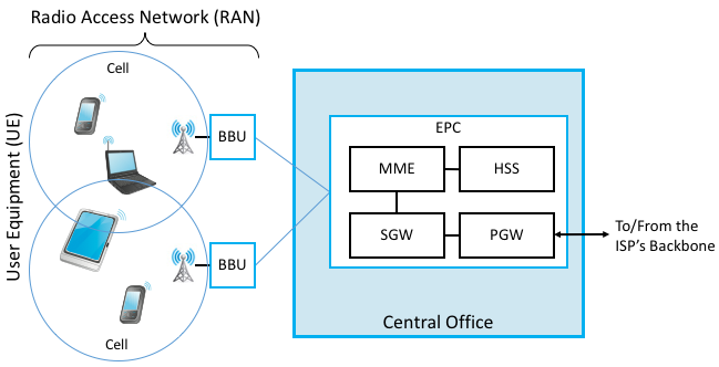
Like 802.11, cellular technology relies on the use of base stations that are connected to a wired network. In the case of the cellular network, the base stations are often called Broadband Base Units (BBU), the mobile devices that connect to them are usually referred to as User Equipment (UE), and the set of BBUs are anchored at an Evolved Packet Core (EPC) hosted in a Central Office. The wireless network served by the EPC is often called a Radio Access Network (RAN).
BBUs currently go by another name—Evolved NodeB, often abbreviated eNodeB or eNB—where NodeB is what the radio unit was called in an early incarnation of cellular networks (and has since evolved). Given that the cellular world continues to evolve at a rapid pace and there's good reason to believe eNB will be out-of-date before long, we have decided to use the more generic and less cryptic BBU.
Figure 2 depicts one possible configuration of the end-to-end scenario, with a few additional bits of detail. The EPC has multiple subcomponents, including an MME (Mobility Management Entity), an HSS (Home Subscriber Server), and an S/PGW (Session/Packet Gateway) pair; the first tracks and manages the movement of UEs throughout the RAN, the second is a database that contains subscriber-related information, and the Gateway pair processes and forwards packets between the RAN and the Internet (it forms the EPC's user plane). We say "one possible configuration" because the cellular standards allow wide variability in how many S/PGWs a given MME is responsible for, making is possible for a single MME to manage mobility across a wide geographic area that is served by multiple Central Offices. Finally, while not explicitly spelled out in Figure 2, it is sometimes the case that the ISP's PON network is used to connect the remote BBUs back to the Central Office.
The geographic area served by a BBU's antenna is called a cell. A BBU could serve a single cell or use multiple directional antennas to serve multiple cells. Cells don't have crisp boundaries, and they overlap. Where they overlap, an UE could potentially communicate with multiple BBUs. At any time, however, the UE is in communication with, and under the control of, just one BBU. As the device begins to leave a cell, it moves into an area of overlap with one or more other cells. The current BBU senses the weakening signal from the phone and gives control of the device to whichever base station is receiving the strongest signal from it. If the device is involved in a call or other network session at the time, the session must be transferred to the new base station in what is called a handoff. The decision making process for handoffs is under the purview of the MME, which has historically been a proprietary aspect of the cellular equipment vendors (although open source MME implementations are now starting to be available).
There have been multiple generations of protocols implementing the cellular network, colloquially known as 1G, 2G, 3G, and so on. The first two generations supported only voice, with 3G defining the transition to broadband access, supporting data rates measured in hundreds of kilobits-per-second. Today, the industry is at 4G (supporting data rates typically measured in the few megabits-per-second) and is in the process of transitioning to 5G (with the promise of a tenfold increase in data rates).
As of 3G, the generational designation actually corresponds to a standard defined by the 3GPP (3rd Generation Partnership Project). Even though its name has "3G" in it, the 3GPP continues to define the standard for 4G and 5G, each of which corresponds to a release of the standard. Release 15, which is now published, is considered the demarcation point between 4G and 5G. By another name, this sequence of releases and generations is called LTE, which stands for Long-Term Evolution. The main takeaway is that while standards are published as a sequence of discrete releases, the industry as a whole is now on a fairly well-defined evolutionary path known as LTE.
The main innovation of LTE's air interface for 5G is the flexibility it provides. 5G uses a hybrid multiplexing scheme called OFDMA (Orthogonal Frequency Division Multiple Access), which intuitively combines frequency-division multiplexing (carving the frequency band into multiple overlapping sub-channels) and time-division multiplexing (allocating one or more sub-channels to a given UE for a certain slot of time). OFDMA also uses a coding scheme known as LDPC (Low Density Parity Check) that ensures the probability of inter-symbol interference for transmissions on adjacent sub-channels is zero. Another way of thinking about LDPC is that the way it encodes bits onto signals includes enough redundancy (i.e., a form of FEC) to ensure the receiver is able recover the original data even when signals overlap. In addition, BBUs also have the ability to increase/decrease the power they use to transmit, effectively allowing them to dynamically change cell size. This makes it possible to move UEs from one cell to another on the fly.
Taken all together, this gives the RAN three degrees of freedom (frequency, time, power), which improves its ability to squeeze the most capacity out of the limited spectrum. More importantly, this flexibility provides opportunities for ISPs to offer new services to their subscribers, supporting applications that range from bandwidth-hungry video and virtual/augmented reality to latency-sensitive autonomous cars and Internet-of-Things. The challenge of 5G is how to control and best take advantage of this flexibility.