
4.4: Lights, Camera, Action
- Page ID
- 13727

A scene in computer graphics can be a complex collection of objects, each with its own attributes. In Subsection 2.4.2, we saw how a scene graph can be used to organize all the objects in a 2D scene. Rendering a scene means traversing the scene graph, rendering each object in the graph as it is encountered. For 3D graphics, scene graphs must deal with a larger variety of objects, attributes, and transforms. For example, it is often useful to consider lights and cameras to be objects and to be able to include them in scene graphs. In this section, we consider scene graphs in 3D, and how to treat cameras and lights as objects.
When designing scene graphs, there are many options to consider. For example, should transforms be properties of object nodes, or should there be separate nodes to represent trans- forms? The same question can be asked about attributes. Another question is whether an attribute value should apply only to the node of which it is a property, or should it be inherited by the children of that node?
A fundamental choice is the shape of the graph. In general, a scene graph can be a directed acyclic graph, or “dag,” which is a tree-like structure except that a node can have several parents in the graph. The scene graphs in Subsection 2.4.2 were dags. This has the advantage that a single node in the graph can represent several objects in the scene, since in a dag, a node can be encountered several times as the graph is traversed. On the other hand, representing several objects with one scene graph node can lead to a lack of flexibility, since those objects will all have the same value for any property encoded in the node. So, in some applications, scene graphs are required to be trees. In a tree, each node has a unique parent, and the node will be encountered only once as the tree in traversed. The distinction between trees and dags will show up when we discuss camera nodes in scene graphs.
Attribute Stack
We have seen how the functions glPushMatrix and glPopMatrix are used to manipulate the transform stack. These functions are useful when traversing a scene graph: When a node that contains a transform is encountered during a traversal of the graph, glPushMatrix can be called before applying the transform. Then, after the node and its descendants have been rendered, glPopMatrix is called to restore the previous modelview transformation.
Something similar can be done for attributes such as color and material, if it is assumed that an attribute value in a scene graph node should be inherited as the default value of that attribute for children of the node. OpenGL 1.1 maintains an attribute stack, which is manipulated using the functions glPushAttrib and glPopAttrib. In addition to object attributes like the current color, the attribute stack can store global attributes like the global ambient color and the enabled state of the depth test. Since there are so many possible attributes, glPushAttrib does not simply save the value of every attribute. Instead, it saves a subset of the possible attributes. The subset that is to be saved is specified as a parameter to the function. For example, the command
glPushAttrib(GL_ENABLED_BIT);
will save a copy of each of the OpenGL state variables that can be enabled or disabled. This in- cludes the current state of GL_DEPTH_TEST, GL_LIGHTING, GL_NORMALIZE, and others. Similarly,
glPushAttrib(GL_CURRENT_BIT);
saves a copy of the current color, normal vector, and texture coordinates. And
glPushAttrib(GL_LIGHTING_BIT);
saves attributes relevant to lighting such as the values of material properties and light properties, the global ambient color, color material settings, and the enabled state for lighting and each of the individual lights. Other constants can be used to save other sets of attributes; see the OpenGL documentation for details. It is possible to OR together several constants to combine sets of attributes. For example,
glPushAttrib(GL_LIGHTING_BIT | GL_ENABLED_BIT)
will save the attributes in both the GL_LIGHTING_BIT set and in the GL_ENABLED_BIT set.
Calling glPopAttrib() will restore all the values that were saved by the corresponding call to glPushAttrib. There is no need for a parameter to glPopAttrib, since the set of attributes that are restored is determined by the parameter that was passed to glPushAttrib.
It should be easy to see how glPushAttrib and glPopAttrib can be used while traversing a scene graph: When processing a node, before changing attribute values, call glPushAttrib to save a copy of the relevant set or sets of attributes. Render the node and its descendants. Then call glPopAttrib to restore the saved values. This limits the effect of the changes so that they apply only to the node and its descendants.
There is an alternative way to save and restore values. OpenGL has a variety of “get” functions for reading the values of various state variables. I will discuss just some of them here. For example,
glGetFloatv( GL_CURRENT_COLOR, floatArray );
retrieves the current color value, as set by glColor*. The floatArray parameter should be an array of float, whose length is at least four. The RGBA color components of the current color will be stored in the array. Note that, later, you can simply call glColor4fv(colorArray) to restore the color. The same function can be used with different first parameters to read the values of different floating-point state variables. To find the current value of the viewport, use
glGetIntegerv( GL_VIEWPORT, intArray );
This will set intArray[0] and intArray[1] to be the x and y coordinates of the lower left corner of the current viewport, intArray[2] to be its width, and intArray[3] to be its height. To read the current values of material properties, use
glGetMaterialfv( face, property, floatArray );
The face must be GL_FRONT or GL_BACK. The property must be GL_AMBIENT, GL_DIFFUSE, GL_SPECULAR, GL_EMISSION, or GL_SHININESS. The current value of the property will be stored in floatArray, which must be of length at least four for the color properties, or length at least one for GL_SHININESS. There is a similar command, glGetLightfv, for reading properties of lights.
Finally, I will mention glIsEnabled(name), which can be used to check the enabled/disabled status of state variables such as GL_LIGHTING and GL_DEPTH_TEST. The parameter should be the constant that identifies the state variable. The function returns 0 if the state variable is disabled and 1 if it is enabled. For example, glIsEnabled(GL_LIGHTING) tests whether lighting is enabled. Suppose that a node in a scene graph has an attribute lit to tell whether that node (and its descendants) should be rendered with lighting enabled. Then the code for rendering a node might include something like this:
int saveLit = glIsEnabled(GL_LIGHTING);
if (lit)
    glEnable(GL_LIGHTING);
else
    glDisable(GL_LIGHTING);
    .
    . // Render the node and its descendants
    .
if (saveLit)
    glEnable(GL_LIGHTING);
else
    glDisable(GL_LIGHTING);
Since glPushAttrib can be used to push large groups of attribute values, you might think that it would be more efficient to use glIsEnabled and the glGet* family of commands to read the values of just those state variables that you are planning to modify. However, recall that OpenGL can queue a number of commands into a batch to be sent to the graphics card, and those commands can be executed by the GPU at the same time that your program continues to run. A glGet command can require your program to communicate with the graphics card and wait for the response. This means that any pending OpenGL commands will have to be sent to the graphics card and executed before the glGet command can complete. This is the kind of thing that can hurt performance. In contrast, calls to glPushAttrib and glPopAttrib can be queued with other OpenGL commands and sent to the graphics card in batches, where they can be executed efficiently by the graphics hardware. In fact, you should generally prefer using glPushAttrib/glPopAttrib instead of a glGet command when possible.
Moving Camera
Let’s turn to another aspect of modeling. Suppose that we want to implement a viewer that can be moved around in the world like other objects. Sometimes, such a viewer is thought of as a moving camera. The camera is used to take pictures of the scene. We want to be able to apply transformations to a camera just as we apply transformations to other objects. The position and orientation of the camera determine what should be visible when the scene is rendered. And the “size” of the camera, which can be affected by a scaling transformation, determines how large a field of view it has. But a camera is not just another object. A camera really represents the viewing transformation that we want to use. Recall that modeling and viewing transformations have opposite effects: Moving objects to the right with a modeling transform is equivalent to moving the viewer to the left with a viewing transformation. (See Subsection 3.3.4.) To apply a modeling transformation to the camera, we really want to apply a viewing transformation to the scene as a whole, and that viewing transformation is the inverse of the camera’s modeling transformation.
The following illustration shows a scene viewed from a moving camera. The camera starts in the default viewing position, at the origin, looking in the direction of the negative z-axis. This corresponds to using the identity as the viewing transform. For the second image, the camera has moved forward by ten units. This would correspond to applying the modeling transformation glTranslatef(0,0,−10) to the camera (since it is moving in the negative z-direction). But to implement this movement as a change of view, we want to apply the inverse operation as a viewing transformation. So, the viewing transform that we actually apply is glTranslatef(0,0,10). This can be seen, if you like, as a modeling transformation that is applied to all the other objects in the scene: Moving the camera ten units in one direction is equivalent to moving all the other objects 10 units in the opposite direction.
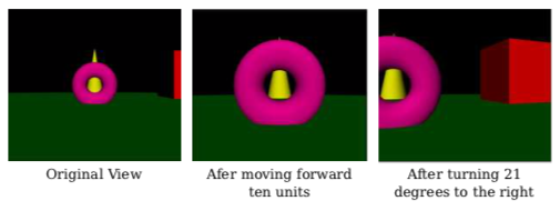
For the third image, the camera has rotated in place by 21 degrees to the right — a 21-degree clockwise rotation about the y-axis — after it has been translated. This can be implemented by the transformation glRotatef(21,0,1,0) — a 21-degree counterclockwise rotation about the y-axis—applied before the translation. Remember that the inverse of a composition of transformations is the composition of their inverses, in the opposite order. Mathematically, using \( T^{-1} \) to represent the inverse of a transformation T, we have that \( (RS)^{-1} = S^{-1} R^{-1} \) for two transformations R and S.
The images in the illustration are from the demo c4/walkthrough.html, which you can try on-line. The demo lets you move around in a scene. More accurately, of course, it lets you change the viewing transformation to see the scene from different viewpoints.
When using scene graphs, it can be useful to include a camera object in the graph. That is, we want to be able to include a node in the graph that represents the camera, and we want to be able to use the camera to view the scene. It can even be useful to have several cameras in the scene, providing alternative points of view. To implement this, we need to be able to render a scene from the point of view of a given camera. From the previous discussion, we know that in order to do that, we need to use a viewing transformation that is the inverse of the modeling transformation that is applied to the camera object. The viewing transform must be applied before any of the objects in the scene are rendered.
When a scene graph is traversed, a modeling transformation can be applied at any node. The modeling transform that is in effect when a given node is encountered is the composition of all the transforms that were applied at nodes along the path that led to given node. However, if the node is a camera node, we don’t want to apply that modeling transform; we want to apply its inverse as a viewing transform. To get the inverse, we can start at the camera node and follow the path backwards, applying the inverse of the modeling transform at each node.
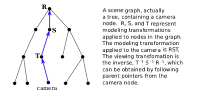
To easily implement this, we can add “parent pointers” to the scene graph data structure. A parent pointer for a node is a link to the parent of that node in the graph. Note that this only works if the graph is a tree; in a tree, each node has a unique parent, but that is not true in a general directed acyclic graph. It is possible to move up the tree by following parent pointers.
We this in mind, the algorithm for rendering the scene from the point of view of a camera goes as follows: Set the modelview transform to be the identity, by calling glLoadIdentity(). Start at the camera node, and follow parent pointers until you reach the root of the tree. At each node, apply the inverse of any modeling transformation in that node. (For example, if the modeling transform is translation by (a,b,c), call glTranslatef(−a,−b,−c).) Upon reaching the root, the viewing transform corresponding to the camera has been established. Now, traverse the scene graph to render the scene as usual. During this traversal, camera nodes should be ignored.
Note that a camera can be attached to an object, in the sense that the camera and the object are both subject to the same modeling transformation and so move together as a unit. In modeling terms, the camera and the object are sub-objects in a complex object. For example, a camera might be attached to a car to show the view through the windshield of that car. If the car moves, because its modeling transformation changes, the camera will move along with it.
Moving Light
It can also be useful to think of lights as objects, even as part of a complex object. Suppose that a scene includes a model of a lamp. The lamp model would include some geometry to make it visible, but if it is going to cast light on other objects in the scene, it also has to include a source of light. This means that the lamp is a complex object made up of an OpenGL light source plus some geometric objects. Any modeling transformation that is applied to the lamp should affect the light source as well as the geometry. In terms of the scene graph, the light is represented by a node in the graph, and it is affected by modeling transformations in the same way as other objects in the scene graph. You can even have animated lights—or animated objects that include lights as sub-objects, such as the headlights on a car.
Recall from Subsection 4.2.3 that a light source is subject to the modelview transform that is in effect at the time the position of the light source is set by glLightfv. If the light is represented as a node in a scene graph, then the modelview transform that we need is the one that is in effect when that node is encountered during a traversal of the scene graph. So, it seems like we should just traverse the graph and set the position of the light when we encounter it during the traversal.
But there is a problem: Before any geometry is rendered, all the light sources that might affect that geometry must already be configured and enabled. In particular, the lights’ positions must be set before rendering any geometry. This means that you can’t simply set the position of light sources in the scene graph as you traverse the graph in the usual way. If you do that, objects that are drawn before the light is encountered won’t be properly illuminated by the light. Similarly, if the light node contains values for any other properties of the light, including the enabled/disabled state of the light, those properties must be set before rendering any geometry.
One solution is to do two traversals of the scene graph, the first to set up the lights and the second to draw the geometry. Since lights are affected by the modelview transformation, you have to set up the modeling transform during the first traversal in exactly the same way that you do in the second traversal. When you encounter the lights during the first traversal, you need to set the position of the light, since setting the position is what triggers the application of the current modelview transformation to the light. You also need to set any other properties of the light. During the first traversal, geometric objects in the scene graph are ignored. During the second traversal, when geometry is being rendered, light nodes can be ignored.