
5.3: Other Features
- Page ID
- 13733

We will finish this chapter with a look at several additional features of three.js. In the process, you will learn about some new aspects of 3D graphics.
Anaglyph Stereo
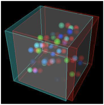
We start with a simple example: anaglyph stereo. Anaglyph refers to 3D images that are meant to be viewed through red/cyan (or red/green or red/blue) glasses. The image contains two copies of the scene, one as viewed from the left eye, drawn using only red, and one as viewed from the right eye, drawn using only green and blue. When the image is viewed through red/cyan glasses, the left eye sees only the left-eye view of the scene and the right eye sees only the right-eye view of the scene. The result is what looks like a real 3D scene, with depth perception. The result isn’t perfect, because screen colors and the color filters in the glasses aren’t perfect. You will see some “ghosts,” where part of the left-eye image gets through to the right eye or vice versa. Anaglyph stereo works best for monochrome images that contain only shades of gray. Color images are more problematic. There are several ways of separating the colors into left and right-eye images, none of them perfect. The one used in three.js works reasonably well.
Here is an example, from the sample program threejs/anaglyph.html, which is identical to threejs/full-window.html, except for the use of anaglyph rendering. For a proper 3D view, you need to look at this image through red/cyan glasses:
In three.js, anaglyph stereo is implemented by the class THREE.AnaglyphEffect. This class is not defined in the main three.js JavaScript file; it’s defined in a separate file named AnaglyphEffect.js, which can be found in the three.js download in the folder examples/js/effects. To use it, you need to include that file in a <script> element in your HTML file. (In fact, my example uses the version of AnaglyphEffect from release 71 of three.js, which I prefer for this example. The newer version is used in the same way.)
The class is very easy to use. The constructor for an object of type THREE.AnaglyphEffect takes an ordinary WebGLRenderer as a parameter. The size of the drawing area is also specified in the constructor (or call the object’s setSize method later to specify the size). For example:
anaglyphRenderer = new THREE.AnaglyphEffect( renderer, canvas.width, canvas.height );
Once you have an AnaglyphEffect, you can use it in place of the WebGLRenderer to render the image:
function render() {
    anaglyphRenderer.render( scene, camera );
}
That’s all there is to it! The scene will be rendered in anaglyph stereo.
User Input
Most real programs require some kind of user interaction. For a web application, of course, the program can get user input using HTML widgets such as buttons and text input boxes. But direct mouse interaction with a 3D world is more natural in many programs.
The most basic example is using the mouse to rotate the scene. In three.js, rotation can be implemented using the class THREE.TrackballControls or the class THREE.OrbitControls. The main difference is that with OrbitControls, the rotation is constrained so that the positive y-axis is always the up direction in the view. TrackballControls, on the other hand, allows completely free rotation. These classes are used in my three.js examples and demos that implement mouse rotation.
The two control classes are not part of the main three.js JavaScript file. To use one of them, you need the JavaScript file OrbitControls.js or TrackballControls.js, which can be found in the folder examples/js/controls in the three.js download.
The two classes are used in a similar way. I will discuss OrbitControls. In my examples, I create a camera and move it away from the origin. I usually add a light object to the camera object, so that the light will move along with the camera, providing some illumination to anything that is visible to the camera. The OrbitControls object is used to rotate the camera around the scene. The constructor for the control object has two parameters, the camera and the canvas on which the scene is rendered. Here is typical setup:
camera = new THREE.PerspectiveCamera(45, canvas.width/canvas.height, 0.1, 100);
camera.position.set(0,15,35);
camera.lookAt( new THREE.Vector3(0,0,0) ); // camera looks toward origin

var light = new THREE.PointLight(0xffffff, 0.6);
camera.add(light);  // viewpoint light moves with camera
scene.add(camera);

controls = new THREE.OrbitControls( camera, canvas );
The constructor installs listeners on the canvas so that the controls can respond to mouse events. It is also necessary to call
controls.update();
just before each rendering of the scene. This method adjusts the camera rotation. The controls are designed to be used in a scene that is constantly being animated, so that the render function is being called regularly. No change will be visible until the render function is called. (In my programs that don’t use animation, I add an extra listener to make sure that controls.update() and render() are called whenever the mouse is dragged. See, for example, the source code for threejs/reflection.html to see how it’s done.)
The controls can also do “panning” (dragging the scene in the plane of the screen) with the right mouse button and “zooming” (scaling the scene) with the middle mouse button or scroll wheel. I generally turn off those features by setting
controls.enablePan = false;
controls.enableZoom = false;
(For TrackballControls, the corresponding properties are controls.noPan and controls.noZoom, which should be set to true to disable panning and zooming.)
A much more interesting form of mouse interaction is to let the user select objects in the scene by clicking on them. The problem is to determine which object the user is clicking. The general procedure is something like this: Follow a ray from the camera through the point on the screen where the user clicked and find the first object in the scene that is intersected by that ray. That’s the object that is visible at the point where the user clicked. Unfortunately, the procedure involves a lot of calculations. Fortunately, three.js has a class that can do the work for you: THREE.Raycaster.
A Raycaster can be used to find intersections of a ray with objects in a scene. (A ray is just half of a line, stretching from some given starting point in a given direction towards infinity.) You can make one raycaster object to use throughout your program:
raycaster = new THREE.Raycaster();
To tell it which ray to use, you can call
raycaster.set( startingPoint, direction );
where both of the parameters are of type THREE.Vector3. Their values are in terms of world coordinates, the same coordinate system that you use for the scene as a whole. The direction must be a normalized vector, with length equal to one. For example, suppose that you want to fire a laser gun.... The startingPoint is the location of the gun, and the direction is the direction that the gun is pointing. Configure the raycaster with those parameters, and you can use it to find out what object is struck by the laser beam.
Alternatively, and more conveniently for processing user input, you can express the ray in terms of the camera and a point on the screen:
raycaster.setFromCamera( screenCoords, camera );
The screenCoords are given as a THREE.Vector2 expressed in clip coordinates. This means the horizontal coordinate ranges from −1 on the left edge of the viewport to 1 on the right, and the vertical coordinate ranges from −1 at the bottom to 1 on the top. (Clip coordinates are called “normalized device coordinates” in three.js.) So, we need to convert from pixel coordinates on a canvas to clip coordinates. Here’s one way to do it, given a mouse event, evt:
var r = canvas.getBoundingClientRect();
var x = evt.clientX - r.left; // convert mouse location to canvas pixel coords
var y = evt.clientY - r.top;

var a = 2*x/canvas.width - 1; // convert canvas pixel coords to clip coords
var b = 1 - 2*y/canvas.height;

raycaster.setFromCamera( new THREE.Vector2(a,b), camera );
Once you have told the raycaster which ray to use, it is ready to find intersections of that ray with objects in the scene. This can be done with the function
raycaster.intersectObjects( objectArray, recursive );
The first parameter is an array of Object3D. The raycaster will search for intersections of its current ray with objects in the array. If the second parameter is true, it will also search descendants of those objects in the scene graph; if it is false or is omitted, then only the objects in the array will be searched. For example, to search for intersections with all objects in the scene, use
raycaster.intersectObjects( scene.children, true );
The return value from intersectObjects is an array of JavaScript objects. Each item in the array represents an intersection of the ray with an Object3D. The function finds all such intersections, not just the first. If no intersection is found, the array is empty. The array is sorted by increasing distance from the starting point of the ray. If you just want the first intersection, use the first element of the array.
An element in the array is an object whose properties contain information about the intersection. Suppose that item is one of the array elements. Then the most useful properties are: item.object, which is the Object3D that was intersected by the ray; and item.point, which is the point of intersection, given as a Vector3 in world coordinates. That information is enough to implement some interesting user interaction.
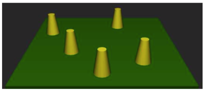
The demo c5/raycaster-input.html uses some basic mouse interaction to let the user edit a scene. The scene shows a number of tapered yellow cylinders standing on a green base. The user can drag the cylinders, add and delete cylinders, and rotate the scene. A set of radio buttons lets the user select which action should be performed by the mouse. Here’s a screenshot from the program:
Let’s look at how the actions are implemented. The only objects are the base and the cylinders. In the program, the base is referred to as ground, and all the objects are children of an Object3D named world. (I use the world object to make it easy to rotate the set of all visible objects without moving the camera or lights.) For all drag, add, and delete actions, I look for intersections of these objects with a ray that extends from the camera through the mouse position:
raycaster.setFromCamera( new THREE.Vector2(a,b), camera );
var intersects = raycaster.intersectObjects( world.children );
If intersects.length is zero, there are no intersections, and there is nothing to do. Otherwise, I look at intersects[0], which represents an intersection with the object that is visible at the mouse position. So, intersects[0].object is the object that the user clicked, and intersects[0].point is the point of intersection.
The Delete action is the simplest to implement: When the user clicks a cylinder, the cylinder should be removed from the scene. If the first intersection is with the ground, then nothing is deleted. Otherwise, the clicked object was a cylinder and should be deleted:
if ( intersects[0].object != ground ) {
    world.remove( intersects[0].object );
    render();
}
For an Add action, we should add a cylinder only if the user clicked the ground. In that case, the point of intersection tells where the cylinder should be added. An interesting issue here is that we get the point of intersection in world coordinates, but in order to add the cylinder as a child of world, I need to know the point of intersection in the local coordinate system for world. The two coordinate systems will be different if the world has been rotated. Fortunately, every Object3D has a method worldToLocal(v) that can be used to transform a Vector3, v, from world coordinates to local coordinates for that object. This method does not return a value; it modifies the coordinates of the vector v. (There is also a localToWorld method.) So, the Add action can be implemented like this:
item = intersects[0];
if (item.object == ground) {
    var locationX = item.point.x;  // world coords of intersection point
    var locationZ = item.point.z;
    var coords = new THREE.Vector3(locationX, 0, locationZ); // y is always 0
    world.worldToLocal(coords); // transform to local coords
    addCylinder(coords.x, coords.z); // adds a cylinder at corrected location
    render();
}
For a Drag action, we can determine which cylinder was clicked using the same test as for delete. However, the problem of moving the cylinder as the user drags the mouse raises a new issue: how do we know where to put the cylinder when the mouse moves? We somehow have to transform a new mouse position into a new position for the cylinder. For that, we can use the raycaster again. My first thought was to create a ray from the camera through the new mouse position, use that ray to find its intersection with the ground, and then to move the cylinder to that point of intersection. Unfortunately, this puts the base of the cylinder at the mouse position, and it made the cylinder jump to the wrong position as soon as I started moving the mouse. I realized that I didn’t want to track the intersection with the ground; I needed to track the intersection with a plane that lies at the same height as the original point of intersection. To implement this, I add an invisible plane at that height just during dragging, and I use intersections with that plane instead of intersections with the ground. (You can have invisible objects in three.js—just set the visible property of the material to false.)
Shadows
One thing that has been missing in our 3D images is shadows. Even if you didn’t notice the lack consciously, it made many of the images look wrong. Shadows can add a nice touch of realism to a scene, but OpenGL, including WebGL, cannot generate shadows automatically. There are ways to compute shadows that can be implemented in OpenGL, but they are tricky to use and they are not completely realistic physically. One method, which is called shadow mapping, is implemented in three.js. Shadow mapping in three.js is certainly not trivial to use, but it is easier than trying to do the same thing from scratch.
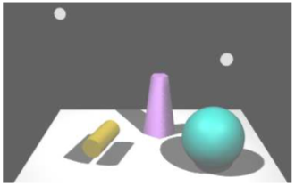
The online demo c5/shadows.html shows a three.js scene that uses shadow mapping. The lights that cast the shadows can be animated, so you can watch the shadows change as the lights move. Here is an image from the demo:
The basic idea of shadow mapping is fairly straightforward: To tell what parts of a scene are in shadow, you have to look at the scene from the point of view of the light source. Things that are visible from the point of view of the light are illuminated by that light. Things that are not visible from the light are in shadow. (This is ignoring the possibility of transparency and indirect, reflected light, which cannot be handled by shadow mapping.) To implement this idea, place a camera at the light source and take a picture. In fact, you don’t need the picture itself. What you need is the depth buffer. After the picture has been rendered, the value stored in the depth buffer for a given pixel contains, essentially, the distance from the light to the object that is visible from the the light at that point. That object is illuminated by the light. If an object is at greater depth than the value stored in the depth buffer, then that object is in shadow. The depth buffer is the shadow map. Now, go back to the point of view of the camera, and consider a point on some object as it is rendered from the camera’s point of view. Is that point in shadow or not? You just have to transform that point from the camera’s viewing coordinates to the light’s viewing coordinates and check the depth of the transformed point. If that depth is greater than the corresponding value in the shadow map, then the point is in shadow. Note that if there are several lights, each light casts its own shadows, and you need a shadow map for each light.
It is computationally expensive to compute shadow maps and to apply them, and shadows are disabled by default in three.js. To get shadows, you need to do several things. You need to enable shadow computations in the WebGL renderer by saying
renderer.shadowMap.enabled = true;
Only DirectionalLights and SpotLights can cast shadows. To get shadows from a light, even after enabling shadows in the renderer, you have to set the light’s castShadow property to true:
light.castShadow = true; // This light will cast shadows.
Furthermore, shadows have to be enabled for each object that will cast or receive shadows. “Receiving” a shadow means that shadows will be visible on that object. Casting and receiving are enabled separately for an object.
object.castShadow = true; // This object will cast shadows.
object.receiveShadow = true; // Shadows will show up on this object.
Even this might not make any shadows show up, and if they do they might look pretty bad. The problem is that you usually have to configure the cameras that are used to make the shadow maps.
Each DirectionalLight or SpotLight has its own shadow camera, which is used to create the shadow map from the point of view of that light. (A DirectionalLight has a property named shadow of type THREE.DirectionalLightShadow, which in turn has a property named camera of type THREE.OrthographicCamera that holds the shadow camera. So, the shadow camera for a directional light dl is dl.shadow.camera.) The shadow camera for a directional light uses an orthographic projection. An orthographic projection is configured by view volume limits xmin, xmax, ymin, ymax, near, and far (see Subsection 3.3.3). For a directional light, dl, these limits correspond to the properties dl.shadow.camera.left, dl.shadow.camera.right, dl.shadow.camera.bottom, dl.shadow.camera.top, dl.shadow.camera.near, and dl.shadow.camera.far. These values are in view coordinates for the shadow camera; that is, they are relative to dl.position. It is important to make sure that all the objects in your scene, or at least those that cast shadows, are within the view volume of the shadow camera. Furthermore, you don’t want the limits to be too big: If the scene occupies only a small part of the camera’s view volume, then only a small part of the shadow map contains useful information—and then since there is so little information about shadows, your shadows won’t be very accurate. The default values assume a very large scene. For a relatively small scene, you might set:
dl.shadow.camera.left = -20;
dl.shadow.camera.right = 20;
dl.shadow.camera.bottom = -20;
dl.shadow.camera.top = 20;
dl.shadow.camera.near = 1;
dl.shadow.camera.far = 30;
The shadow camera for a spotlight is of type THREE.PerspectiveCamera and uses a perspective projection. (The use of a camera with a limited view is why you can have shadows from spotlights but not from point lights.) For a spotlight sl, the shadow camera is configured by the properties sl.shadow.camera.near, sl.shadow.camera.far, and sl.shadow.camera.fov (where “fov” is the vertical field of view angle, given in degrees rather than radians). The default value for fov is probably OK, except that if you change the spotlight’s cutoff angle, you will want to change the fov to match. But you should be sure to set appropriate values for near and far, to include all of your scene and as little extra as is practical. Again, near and far are distances from sl.position.
To get more accurate shadows, you might want to increase the size of the shadow map. The shadow map is a kind of texture image which by default is 512 by 512 pixels. You can increase the accuracy of the shadows by using a larger shadow map. To do that for a light, light, set the values of the properties light.shadow.mapSize.width and light.shadow.mapSize.height. For example,
light.shadow.mapSize.width = 1024;

light.shadow.mapSize.height = 1024;
I’m not sure whether power-of-two values are absolutely required here, but they are commonly used for textures.
Cubemap Textures and Skyboxes
We have created and viewed simple scenes, shown on a solid-colored background. It would be nice to put our scenes in an “environment” such as the interior of a building, a nature scene, or a public square. It’s not practical to build representations of such complex environments out of geometric primitives, but we can get a reasonably good effect using textures. The technique that is used is called a skybox. A skybox is a large cube where a different texture is applied to each face of the cube. The textures are images of some environment. For a viewer inside the cube, the six texture images on the cube fit together to provide a complete view of the environment in every direction. The six texture images together make up what is called a cubemap texture. The images must match up along the edges of the cube to form a seamless view of the environment.
A cube map of an actual physical environment can be made by taking six pictures of the environment in six directions: left, right, up, down, forward, and back. (More realistically, it is made by taking enough photographs to cover all directions, with overlaps, and then using soft- ware to “stitch” the images together into a complete cube map.) The six directions are referred to by their relation to the coordinate axes as: positive x, negative x, positive y, negative y, positive z, and negative z, and the images must be listed in that order when you specify the cube map. Here is an example. The first picture shows the six images of a cube map laid out next to each other. The positive y image is at the top, the negative y image is at the bottom. In between are the negative x, positive z, positive x, and negative z images laid out in a row. The second picture shows the images used to texture a cube, viewed here from the outside. You can see how the images match up along the edges of the cube:
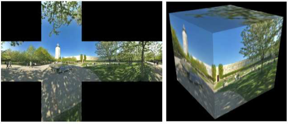
(This cube map, and others used in this section, are by Emil Persson, who has made a large number of cube maps available for download at http://www.humus.name/index.php?page=Textures under a creative commons license.)
For a skybox, a very large cube is used. The camera, lights, and any objects that are to be part of the scene are inside the cube. The skybox cube itself should not be lit; any lighting of the environment is already part of the cube map texture images.
One way to apply a cube map to a cube — but not the method that gives the best result for a skybox — is to load the cube map as a set of six separate texture images, and then use an array of materials on the cube to apply a different texture image to each face. The material for each face should be a MeshBasicMaterial, which does not use lighting. The six images can be loaded using THREE.TextureLoaders and can be applied to a material using the map property of the material, as discussed in Subsection 5.2.3 For example:
var textureURLs = [  // URLs of the six faces of the cube map
        "cubemap-textures/park/posx.jpg",   // Note:  The order in which
        "cubemap-textures/park/negx.jpg",   //   the images are listed is
        "cubemap-textures/park/posy.jpg",   //   important!
        "cubemap-textures/park/negy.jpg",
        "cubemap-textures/park/posz.jpg",
        "cubemap-textures/park/negz.jpg"
    ];

var materials = [];
for (var i = 0; i < 6; i++) {
    var texture = new THREE.TextureLoader().load( textureURLs[i] );
    materials.push( new THREE.MeshBasicMaterial( {
        color: "white",  // Color will be multiplied by texture color.
        side: THREE.DoubleSide,  // IMPORTANT: To see the inside of the cube,
                                 //            back faces must be rendered!
        map: texture
    } ) );
}

cube = new THREE.Mesh( new THREE.CubeGeometry(100,100,100), materials );
(This code does not include a way to get the scene redrawn after the textures have finished loading. That’s fine if an animation is running. If not, you have to use a callback function in the texture loader to do the redrawing.)
However, WebGL has built-in support for using cubemap textures directly. It’s possible to load the six images of a cube map into a single object representing the cubemap texture as a whole. To map such a cubemap texture onto a skybox, three.js requires a new kind of material called THREE.ShaderMaterial. A shader material uses custom vertex and fragment shaders to render the image. (Vertex shaders and fragment shaders are programs that run on the GPU. The are required for rendering images in WebGL, and we will start working with them directly in the next chapter.) The shaders that are required in this case are defined in a three.js shader library. Here’s an example of making a skybox using a cubemap texture. This code is copied from examples in the three.js download. It uses the same textureUrls array as the previous example:
var texture = new THREE.CubeTextureLoader().load( textureURLs );

var shader = THREE.ShaderLib[ "cube" ]; // contains the required shaders
shader.uniforms[ "tCube" ].value = texture; // data for the shaders
var material = new THREE.ShaderMaterial( {
        // A ShaderMaterial uses custom vertex and fragment shaders.
    fragmentShader: shader.fragmentShader,
    vertexShader: shader.vertexShader,
    uniforms: shader.uniforms,
    depthWrite: false,
    side: THREE.BackSide
} );

cube = new THREE.Mesh( new THREE.CubeGeometry( 100, 100, 100 ), material );
The sample program threejs/skybox.html shows two WebGL scenes that use cube maps. In the first, the texture is applied using an array of six materials, and the cube is viewed from the outside. In the second, the texture is a applied to a skybox cube as a cubemap texture, and the cube is viewed from the inside.
Reflection and Refraction
A reflective surface shouldn’t just reflect light—it should reflect its environment. Three.js can use environment mapping to simulate reflection. (Environment mapping is also called “reflection mapping.”) Environment mapping uses a cube map texture. Given a point on a surface, a ray is cast from the camera position to that point, and then the ray is reflected off the surface. The point where the reflected ray hits the cube determines which point from the texture should be mapped to the point on the surface. For a simulation of perfect, mirror-like reflection, the surface point is simply painted with the color from the texture. Note that the surface does not literally reflect other objects in the scene. It reflects the contents of the cube map texture. However, if the same cube map texture is used on a skybox, and if the skybox is the only other object in the scene, then it will look like the surface is a mirror that perfectly reflects its environment.
This type of reflection is very easy to do in three.js. You only need to make a MeshBasicMaterial and set its envMap property equal to the cubemap texture object. For example, if texture is the texture object obtained using a THREE.CubeTextureLoader, as in the skybox example above, we can make a sphere that perfectly reflects the texture by saying:
var geometry = new THREE.SphereGeometry(1,32,16);
var material = new THREE.MeshBasicMaterial( {
        color: "white",  // Color will be multiplied by the environment map.
        envMap: texture  // Cubemap texture to be used as an environment map.
    } );
var mirrorSphere = new THREE.Mesh( geometry, material );
For the effect to look good, you would want to use the same texture on a skybox. Note that no lighting is necessary in the scene, since both the skybox and the sphere use a MeshBasicMaterial. The colors seen on the sphere come entirely from the environment map and the basic color of the sphere material. The environment map color is multiplied by the basic color. In this example, the basic color of the material is white, and the sphere color is exactly equal to the color from the texture. With a different base color, the environment map texture would be “tinted” with that color. You could even apply a regular texture map to the sphere, to be used in place of the color, so that the reflection of the skybox would be combined with the texture.
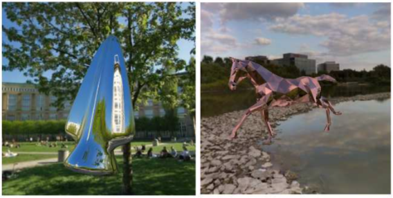
The sample program threejs/reflection.html demonstrates environment mapping. It can show a variety of environment-mapped objects, with a variety of skybox textures, and it has several options for the base color of the object. Here are two images from that program. The one on the left shows a reflective arrowhead shape with a white base color. On the right, the object is a model of a horse (taken from the three.js download) whose base color is pink:
A very similar program is available as a demo in the on-line version of this section.
Three.js can also do refraction. Refraction occurs when light passes through a transparent or translucent object. A ray of light will be bent as it passes between the inside of the object and the outside. The amount of bending depends on the so-called “indices of refraction” of the material outside and the material inside the object. More exactly, it depends on the ratio between the two indices. Even a perfectly transparent object will be visible because of the distortion induced by this bending.
In three.js, refraction is implemented using environment maps. As with reflection, a refracting object does not show its actual environment; it refracts the cubemap texture that is used as the environment map. For refraction, a special “mapping” must be used for the environment map texture. The mapping property of a texture tells how that texture will be mapped to a surface. For a cubemap texture being used for refraction, it should be set to THREE.CubeRefractionMapping. (The default value of this property in a cubemap texture is appropriate for reflection rather than refraction.) Here is an example of loading a cubemap texture and setting its mapping property for use with refraction:
texture = new THREE.CubeTextureLoader().load( textureURLs );
texture.mapping = THREE.CubeRefractionMapping;
In addition to this, the refractionRatio property of the material that is applied to the refracting object should be set. The value is a number between 0 and 1; the closer to 1, the less bending of light. The default value is so close to 1 that the object will be almost invisible. This example uses a value of 0.6:
var material = new THREE.MeshBasicMaterial( {

        color: "white",

        envMap: texture,

        refractionRatio: 0.6

    } );
This gives a strong refractive effect. If you set the material color to something other than white, you will get something that looks like tinted glass. Another property that you might set is the reflectivity. For a refractive object, this value tells how much light is transmitted through the object rather than reflected from its surface. The default value, 1, gives 100% transmission of light; smaller values make objects look like they are made out of “cloudy” glass that blocks some of the light.
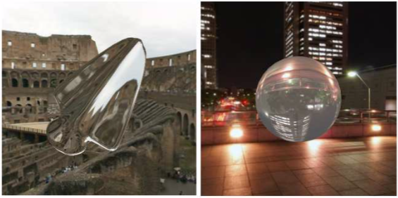
The sample program threejs/refraction.html is a copy of reflection.html that has been modified to do refraction instead of reflection. The objects look like they are made of glass instead of mirrors. An option has been added to make the glass look cloudy. The following images are from that program. A perfectly transmissive arrowhead is shown in the first image, and a cloudy sphere in the second. Notice how the sphere shows an inverted image of the objects behind it:
In my reflection and refraction examples, the environment is a skybox, and there is a single object that reflects or refracts that environment. But what if a scene includes more than one object? The objects won’t be in the cubemap texture. If you use the cubemap texture on the objects, they won’t reflect or refract each other. There is no complete solution to this problem in WebGL. However, you can make an object reflect or refract other objects by making an environment map that includes those objects. If the objects are moving, this means that you have to make a new environment map for every frame. Recall that an environment map can be made by taking six pictures of the environment from different directions. Three.js has a kind of camera that can do just that, THREE.CubeCamera. I won’t go into the full details, but a CubeCamera can take a six-fold picture of a scene from a given point of view and make a cubemap texture from those images. To use the camera, you have to place it at the location of an object—and make the object invisible so it doesn’t show up in the pictures. Snap the picture, and apply it as an environment map on the object. For animated scenes, you have to do this in every frame, and you need to do it for every reflective/refractive object in the scene. Obviously, this can get very computationally expensive! And the result still isn’t perfect. For one thing, you won’t see multiple reflections, where objects reflect back and forth on each other several times. For that, you need a different kind of rendering from the one used by OpenGL. We will return to the topic of dynamic cubemaps in Subsection 7.4.4 and to alternative rendering techniques in Chapter 8.