
3.6: Adventures in Radioland
- Page ID
- 11106

For the remainder of this chapter we leave wires (and fiber) behind, and contemplate the transmission of packets via radio, freeing nodes from their cable tethers. Wi-fi (3.7 Wi-Fi) and mobile wireless (3.8 WiMAX and LTE) are now ubiquitous. But radio is not quite like wire, and wireless transmission of packets brings several changes.
3.6.1 Privacy
It’s hard to tap into wired Ethernet, especially if you are locked out of the building. But anyone can receive wireless transmissions, often from a considerable distance. The data breach at TJX Corporation was achieved by attackers parking outside a company building and pointing a directional antenna at it; encryption was used but it was weak (see 22 Security and 22.7.7 Wi-Fi WEP Encryption Failure). Similarly, Internet café visitors generally don’t want other patrons to read their email. Radio communication needs strong encryption.
3.6.2 Collisions
Ethernet-like collision detection is no longer feasible over radio. This has to do with the relative signal strength of the remote signal at the local transmitter. Along a wire-based Ethernet the remote signal might be as weak as 1/100 of the transmitted signal but that 1% received signal is still detectable during transmission. However, with radio the remote signal might easily be as little as 1/1,000,000 of the transmitted signal (-60 dB), as measured at the transmitting station, and it is simply overwhelmed during transmission.
As a result, wireless protocols must be constructed appropriately. We will look at how Wi-Fi handles this in its most common mode of operation in 3.7.1 Wi-Fi and Collisions. Wi-Fi also supports its PCF mode (3.7.7 Wi-Fi Polling Mode) that involves fewer (but not zero) collisions through the use of central-point polling. Finally, WiMAX and LTE switch from polling to scheduling to further reduce collisions, though the potential for collisions is still inevitable when new stations join the network.
It is also worth pointing out that, while an Ethernet collision affects every station in the physical Ethernet (the “collision domain”), wireless collisions are local, occuring at the receiver. Two stations can transmit at the same time, and in range of one another, but without a collision! This can happen if each of the relevant receivers is in range of only one of the two transmitting stations. As an example, suppose three stations are arranged linearly, A–C–B, with the A–C and C–B distances just under the maximum effective range. When A and B both transmit there is indeed a collision at C. But when C and B transmit simultaneously, A may receive C’s signal just fine, as B’s is too weak to interfere.
3.6.3 Hidden Nodes
In wireless communication, two nodes A and B that are not in range of one another – and thus cannot detect one another – may still have their signals interfere at a third node C. This creates an additional complication to collision handling. See 3.7.1.4 Hidden-Node Problem.
3.6.4 Band Width
To radio engineers, “band width” means the frequency range used by a signal, not the data transmission rate. No information can be conveyed using a single frequency; even signaling by switching a carrier frequency off and on at a low rate “blurs” the carrier into a band of nonzero width.
In keeping with this we will for the remainder of this chapter use the term “data rate” for what we have previously called “bandwidth”. We will use the terms “channel width” or “width of the frequency band” for the frequency range.
All else being equal, the data rate achievable with a radio signal is proportional to the channel width. The constant of proportionality is limited by the Shannon-Hartley theorem: the maximum data rate divided by the width of the frequency band is log2(1+SNR), where SNR is the signal to noise power ratio. Noise here is assumed to have a specific statistical form known as Gaussian white noise. If SNR is 127, for example, and the width of the frequency band is 1 MHz, then the maximum theoretical data rate is 7 Mbps, where 7 = log2(128). If the signal power S drops by about half so SNR=63, the data rate falls to 6 Mbps, as 6 = log2(64); the relationship between signal power and data rate is logarithmic.
3.6.4.1 OFDM
The actual data rate achievable, for a given channel width and SNR, depends on the signal encoding, or modulation, mechanism. Most newer modulation mechanisms use “orthogonal frequency-division multiplexing”, OFDM, or some variant.
A central feature of OFDM is that one wider frequency band is divided into multiple narrow subchannels; each subchannel then carries a proportional fraction of the total information signal, modulated onto a subchannel-specific carrier. All the subchannels can be allocated to one transmission at a time (time-division multiplexing, 4.2 Time-Division Multiplexing), or disjoint sets of subchannels can be allocated to different transmissions that can then proceed (at proportionally lower data rates) in parallel. The latter is known as frequency-division multiplexing.
In many settings OFDM comes reasonably close to the Shannon-Hartley limit. Perhaps more importantly, OFDM also performs reasonably well with multipath interference, below, which is endemic in urban and building-interior environments with their many reflective surfaces. Multipath interference is, however, not necessarily comparable to the Gaussian noise assumed by the Shannon-Hartley theorem. We will not address further technical details of OFDM here, except to note that implementation usually requires some form of digital signal processing.
The OFDMA variant, with the MA standing for Multiple Access, allows multiple users to use nonoverlapping sets of subchannels, thus allowing simultaneous transmission. It is an option available in 802.11ax.
3.6.5 Cost
Another fundamental issue is that everyone shares the same radio spectrum. For mobile wireless providers, this constraint has driven prices to remarkable levels; the 2014-15 FCC AWS-3 auction raised almost $45 billion for 65 MHz (usable throughout the entire United States). This works out to somewhat over $2 per megahertz per phone. The corresponding issue for Wi-Fi users in a dense area is that all the available Wi-Fi bandwidth may be in use. Inside busy buildings one can often see dozens of Wi-Fi access points competing for the same Wi-Fi channel; the result is that no user will be getting close to the nominal data rates of 3.7 Wi-Fi.
Higher data rates require wider frequency bands. To reduce costs in the face of fixed demand, the usual strategy is to make the coverage zones smaller, either by reducing power (and adding more access points as appropriate), or by using directional antennas, or both.
3.6.6 Multipath
While a radio signal generally covers a wide area – even with ordinary directional antennas – it does so in surprisingly non-uniform ways. A signal may reach a receiver through a line-of-sight path and also several reflected paths, possibly of varying length. In addition to reflection, the signal may be subject to reflection-like scattering and diffraction. All of this together is known as multipath interference (or, if analog audio is involved, multipath distortion; in the analog TV era this was ghosting).

The picture above shows two transmission paths from A to B. The respective carrier paths may interfere with or supplement one another. The longer delay of the reflecting path (red) wil also delay its encoded signal. The result, shown at right, is that the line-of-sight and reflected data symbols may overlap and interfere with each other; this is known as intersymbol interference. Multipath interference may even change the meaning of the data symbol as seen by the receiver; for example, the red and black low data-signal peaks above at the point of the vertical dashed line may sum together so as to be received as a higher peak (assuming the underlying carriers are in sync).
Multipath interference tends to lead to wide fluctuations in signal intensity with a period of about half a wavelength; this phenomenon is known as multipath fading. As an example, the wavelength of FM radio stations in the United States is about 3 meters; in fringe reception areas it is not uncommon to pull a car forward a quarter wavelength and have a station go from clear to indecipherable, or even for reception to switch to another station (on the same frequency but transmitted from another location) altogether.
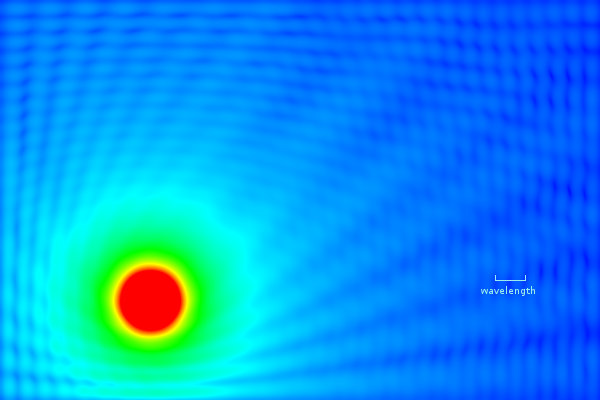
Signal-intensity map (simulated) in a room with walls with 40% reflectivity
The picture above is from a mathematical simulation intended to illustrate multipath fading. The walls of the room reflect 40% of the signal from the transmitter located in the orange ball at the lower left. The transmitter transmits an unmodulated carrier signal, which may be reflected off the walls any number of times; at any point in the room the total signal intensity is the sum over all possible reflection paths. On the right-hand side, the small-scale blue ripples represent the received carrier strength variation due to multipath interference between the line-of-sight and all the reflected paths. Note that the ripple size is about half a wavelength.
In comparison to this simulated intensity map, real walls tend to have a lower reflectivity, real rooms are not two-dimensional, and real carriers are modulated. However, real rooms also introduce scattering, diffraction and shadowing from objects within, and significant (3× to 10×) multipath-fading signal-strength variations are common in actual wireless settings.
Multipath fading can be either flat – affecting all frequencies more or less equally – or selective – affecting some frequencies differently than others. It is quite possible for an OFDM channel (3.6.4.1 OFDM) to encounter selective fading of only some of its subchannel frequencies.
Generally, multipath interference is a problem that engineers go to great lengths to overcome. However, as we shall see in 3.7.3 Multiple Spatial Streams, multipath interference can sometimes be put to positive use by allowing almost-adjacent antennas to transmit and receive independent signals, thus increasing the effective throughput.
For an alternative example of multipath interference in which the signal strength has no ripples, see exercise 13.0.
3.6.7 Power
If you are cutting the network cable and replacing it with wireless, there is a good chance you will also want to cut the power cable as well and replace it with batteries. This tends to make power consumption a very important issue. The Wi-Fi standard has provisions for minimizing power usage by allowing a device to “doze” most of the time, waking periodically to check if any packets are ready to be sent to it (see 3.7.4.1 Joining a Network). The 6LoWPAN project (IPv6 Low-power Wireless Personal Area Network) is intended to support very low-power devices; see RFC 4919 and RFC 6282.
3.6.8 Tangle
Wireless is also used simply to replace cords and their attendant tangle, and, of course, the problem of incompatible connectors. The low-power Bluetooth wireless standard is commonly used as a cable alternative for things like computer mice and telephone headsets. Bluetooth is also a low-power network; for many applications the working range is about 10 meters. ZigBee is another low-power small-scale network.