
3.2: Addition in MIPS Assembly
- Page ID
- 27107

3.2.1 Addition operators
There are 4 real addition operators in MIPS assembly. They are:
addoperator, which takes the value of theRsandRtregisters containing integer numbers, adds the numbers, and stores the value back to theRdregister. The format and meaning are:format:
add Rd, Rs, Rtmeaning:
Rd <- Rs + Rtaddioperator, which takes the value of Rs and adds the 16 bit immediate value in the instruction, and stores the result back in Rt. The format and meaning are:format:
addi Rt, Rs, Immediatemeaning:
Rt <- Rs + Immediateadduoperator, which is the same as the add operator, except that the values in the registers are assumed to be unsigned, or whole, binary numbers. There are no negative values, so the values run from 0..232-1. The format and the meaning are the same as the add operator above:format:
addu Rd, Rs, Rtmeaning:
Rd <- Rs + Rtaddiuoperator, which is the same as theaddioperator, but again the numbers are assumed to be unsigned8:format:
addiu Rt, Rs, Immediatemeaning:
Rt <- Rs + Immediate
In addition to the real operators, there are a number of pseudo add operators, which are:
addusing a 16 bit immediate value. This is shorthand for the add operator to implement an addi operator. The same is principal applies for theadduif an immediate value is used, and the operator is converted into anaddiu. The format, meaning, and translation of this instruction is:format:
add Rt, Rs, Immediatemeaning:
Rt <- Rs + Immediatetranslation:
addi Rt, Rs, Immediateadd,addi,addu, oraddiuwith a 32 bit immediate value. When considering this operator, it is important to remember that in the real I format instruction the immediate value can only contain 16 bits. So if an immediate instruction contains a number needing more than 16, the number must be loaded in two steps. The first step is to load the upper 16 bits of the number into a register using the Load Upper Immediate (lui) operator 9, and then to load the lower 16 bits using the using an Or Immediate (ori) operator. The addition is then done using the R instruction add operator. Thus the instruction:addi Rt, Rs, (32 bit) Immediatewould be translated to:
lui $at10, (upper 16 bits) Immediate #load upper 16 bits into $at ori $at, $at, (lower 16 bits) Immediate #load lower 16 bits into $at add Rt, Rs, $at11
The next section will show a program using add operations which will illustrate all of these operations.
3.2.2 Addition Examples
This section will implement and assemble examples of using the different formats of the add operator. Following the program will be a number of screen shots taken from MARS to provide a detailed discussion of the program.
    Program 3-1: Addition Examples

    # File: Program3-1.asm
    # Author: Charles Kann
    # Purpose: To illustrate some addition operators

    # illustrate R format add operator
    li $t1, 100
    li $t2, 50
    add $t0, $t1, $t2

    # illustrate add with an immediate. Note that
    # an add with a pseudo instruction translated
    # into an addi instruction
    addi $t0, $t0, 50
    add $t0, $t0, 50

    # using an unsign number. Note that the # result is not what is expected
    # for negative numbers.
    addiu $t0, $t2, -100

    # addition using a 32 immediate. Note that 5647123
    # base 10 is 0x562b13
    addi $t1, $t2, 5647123
To begin exploring this program, assemble the program and bring up the execute screen, as illustrated in the follow screen capture. One important detail in this screen capture is the representation of the program found in two columns. The first column is titled Source, and this column contains the program exactly as you entered it. The second column is titled Basic, and this contains the source code as it is given to the assembler. There are a number of changes between the original source code and the basic code. The basic code has had all of the register mnemonics changed to the register numbers. But the bigger change is that all of the instructions using pseudo operators have been changed into instructions using one or more real operators.
Example
In line 14 which has the statement add $t0, $t0, 50 , the add operator has been changed into the addi operator, as was discussed in the previous section. The same is true of line 22, where the addi $t1, $t2, 5647123 instruction has been covered to a lui, ori, and R format add instruction.
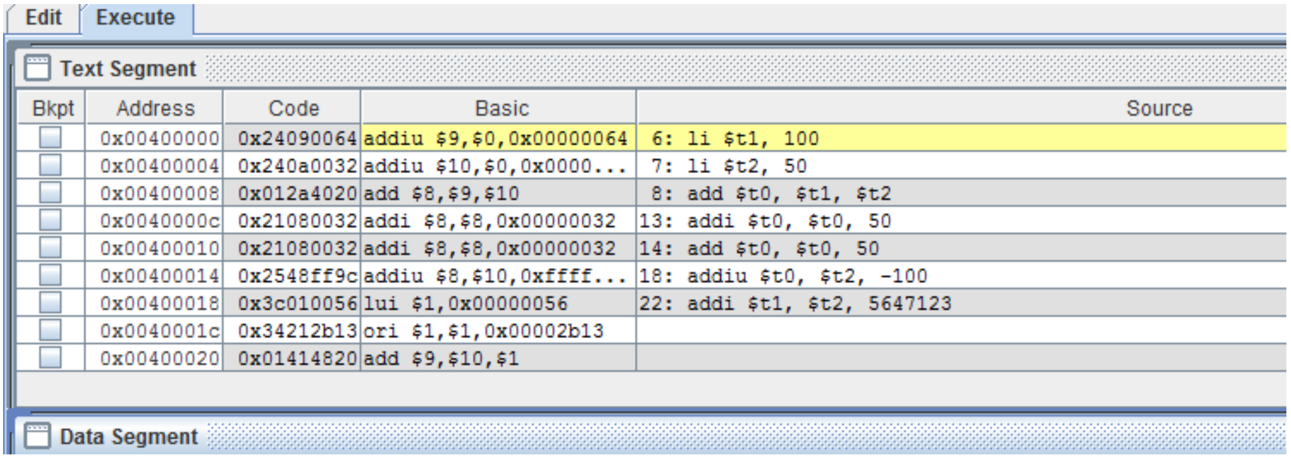
This output shows that some operators that were used in the previous chapter are actually pseudo operators. The li operator was suspect because it only had 2 address parameters, a source and a destination, and indeed it turns out not to be a real operator.
It is often useful to look at the Basic column in MARS to see how your source is actually presented to the assembler.
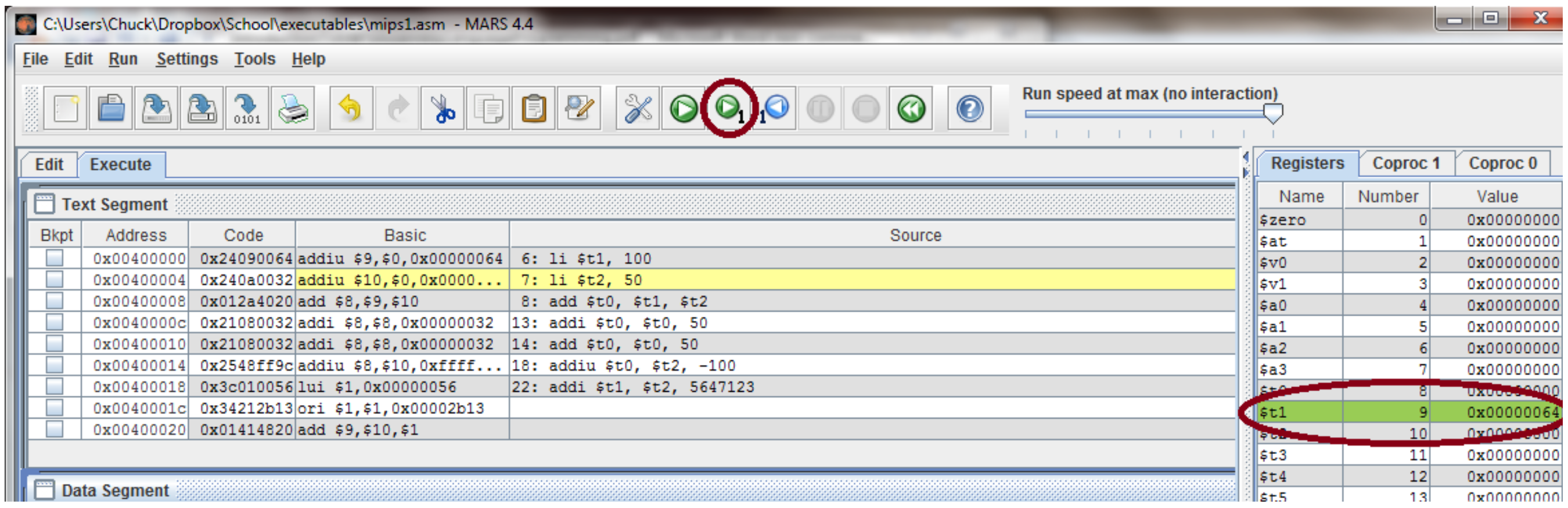
Next notice that in figure 3-2 the first line of the program is highlighted in yellow. This means that the program is ready to execute at the first line in the program. Clicking on the green arrow as shown in figure 3-3 the program has executed the first line of the program, and is waiting to run at the second line of the program. As a result of running the first line, the register $t1 ($9) has been updated to contain the value 100 (0x64), which is shown in figure 3-3.
Continue running the program, and you will note that the next line to execute will always be highlighted in yellow, and the last register to be changed will be highlighted in green. When line 7 is run, line 8 is yellow and $t2 ($10) contains the value 0x32 (5010) and is highlighted in green. After the addition at line 8, line 13 is highlighted in yellow, and register $t0 ($8) contains 0x96 (or 15010). Continue to step through the program until line 18 highlighted and ready to run. At this point register $t0 has the value 0xfa (25010). Once this statement is executed, the value in $t0 changes from 0xfa changes to 0xffffffce (-5010), not 0x96 (15010) as you might expect.
3.2.3 Introduction to pseudo code
Writing a program in assembly language results in very large, complex programs which become hard to write, understand, and debug. HLL were designed to abstract away a large portion of the complexity introduced in writing assembly code. Even though all programs eventually require this level of complexity, a compiler is introduced to translate the relatively simpler structure of a HLL to the more complex assembly language code.
One way to write assembly code would then be to first write the code in a HLL, and perform the translation to assembly in a similar manner to a compiler. However HLL must be formally defined to allow a compiler work properly, and some of the translations implemented by a compiler are less than straight forward.
What is really needed is a language which can be used to specify the salient points of code in a higher level form, but with less formality so that the translation to assembly is relatively straight forward and simple. The language which is usually used for this is called pseudo code. As its name implies, pseudo code is not a formal language. Instead it is a very rough set of malleable concepts which can be used to produce an outline an assembly program. The language itself only includes enough detail to allow a programmer to understand what needs to done. How the program is actually implementated is left up to the programmer.
Pseudo code is also useful in that new concepts can be added to the language as needed, so long as the meaning of those constructs is clear to a programmer. This means that the language can be easily changed as the needs of the programmer change.
While there is no one formal definition of pseudo code, this text will give some conventions it will use. Consider the following pseudo code program to read two numbers, add them, and print the result back to the user.
main {
        register int i = input("Please enter the first value to add: ");
        register int j = input("Please enter the second value to add: ");
        register int k = i + j;
        print("The result is " + k);
     }
This program tells the assembly language programmer to create a program that will contain 3 integer values. The use of the register modifier on the int declaration tells the programmer that they should use a save register (s0..s7) if possible to maintain these values. If the register modifier is not used, the programmer has a choice to use memory or registers to store the values. In addition, there will be a volatile modifier used later, which will mean that the programmer must use a memory variable. Note that the register modifier is only a suggestion. Since the number of save registers is limited to 8, there is a possibility that one will not be available to the programmer, and the variable might need to be written to memory.
The next construct from this pseudo code that will be discussed is the input and print. These are purposefully made to look like HLL methods to be more easily understood by programmers. But the programmer can implement them in any manner they choose, as macros, as subprograms, or directly in the code. They tell the programmer that for the input, a prompt should be written to the console, and a value read from the user and stored. The print tells the program to write out a string and append the result of the addition.
This simple program will be translated into MIPS assembly in the next section. Note how much more complex the program becomes.
3.2.4 Assembly language addition program
The following assembly language program implements the pseudo code program from the last section. Comments on the code will following in the next section of the text.
# File name: Program3-2.psc
# Author: Charles Kann
# Purpose: To illustrate how to translate a pseudo code program into assembly
#
# Pseudo Code
# main
# {
#  register int i = input("Please enter the first value to add: ");
#  register int j = input("Please enter the second value to add: ");
#  register int k = i + j;
#  print("The result is " + k);
# }

.text
.globl main
main:
    # Register conventions
    # i is $s0
    # j is $s1
    # k is $s2
    # register int i =
    # input("Please enter the first value to add: ");
    addi $v0, $zero, 4
    la $a0, prompt1
    syscall
    addi $v0, $zero, 5
    syscall
    move $s0, $v0

    # register int j =
    # input("Please enter the second value to add: ");
    addi $v0, $zero, 4
    la $a0, prompt2
    syscall
    addi $v0, $zero, 5
    syscall
    move $s1, $v0

    # register int k = i + j;
    add $s2, $s1, $s0

    # print("The result is " + k);
    addi $v0, $zero, 4
    la $a0, result
    syscall
    addi $v0, $zero, 1
    move $a0, $s2
    syscall

    #End the program
    addi $v0, $zero, 10
    syscall

.data
prompt1: .asciiz "Please enter the first value to add: "
prompt2: .asciiz "Please enter the second value to add: "
result: .asciiz "The result is "
3.2.5 Assembly language addition program commentary
Since much of this program uses operators and concepts from previous sections, it does not require as many comments. However the following points are worth noting.
- Preamble comments are still important in any program. However it is a very good idea to include the pseudo code as part of the preamble, to show how the program was developed.
- The
moveoperator is a strange operator with only two parameters. This seems strange, and would lead one to believe that it is probably a pseudo operator. You will be asked to show this in the exercises at the end of the chapter.
8 Note that the instruction addiu $t1, $t2, -100 is perfectly valid, but as a later example program will show, the results are not what you would expect. The value of -100 is converted into a binary number. When negative numbers are used, the behavior, while defined, is not intuitive. Unsigned numbers means only whole numbers, and when using unsigned numbers it is best to only use unsigned whole numbers.
9 The lui operator loads the upper 16 bits of a register with the high 16 bits in the immediate value.
10 The $at is the assembler reserved register. The programmer cannot access it directly, it is reserved for the assembler to use as scratch space, as is done here.
11 Be careful when using immediate values, as they can be either numbers or bit strings. This can create confusion if you mix hex values with decimal numbers (e.g. 0xffff and -1). So the rule will be given that when using arithmetic (addition, subtraction, multiplication, and division), always use decimal numbers. When using logical operations (and, or, not, xor, etc), always use hex values. The problems with intermingling these will be explored in the problems at the end of the chapter.