
4.1: Instruction Formats
- Page ID
- 27113

The MIPS computer is organized in a 3-address format. Generally all instructions will have 3 addresses associated with them. For example, the instruction "ADD Rd, Rs, Rt" uses three registers, the first address is the destination of the result, and the second and third are the two inputs to the ALU. The instruction "ADDI Rt, Rs, immediate" also uses three addresses, but in this case the third address is an immediate value.
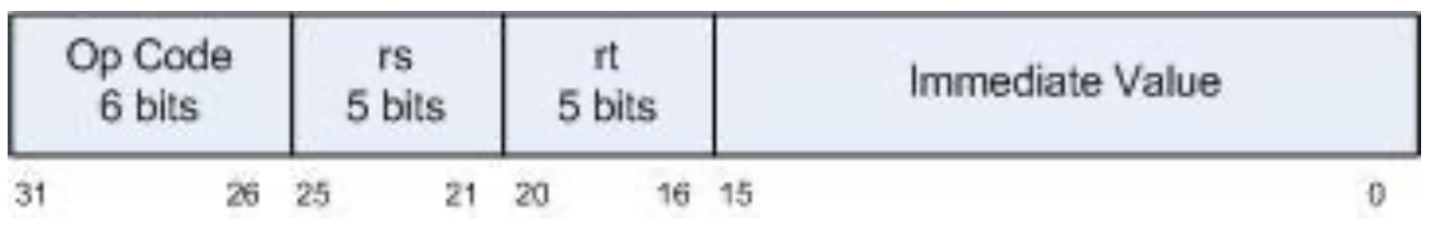
In MIPS there are only 3 ways to format instructions. They are the R-format (register), the I- format (immediate), and the J-format (jump). This chapter will only cover R-format and I- format instructions. The R-format and I-format are shown below.
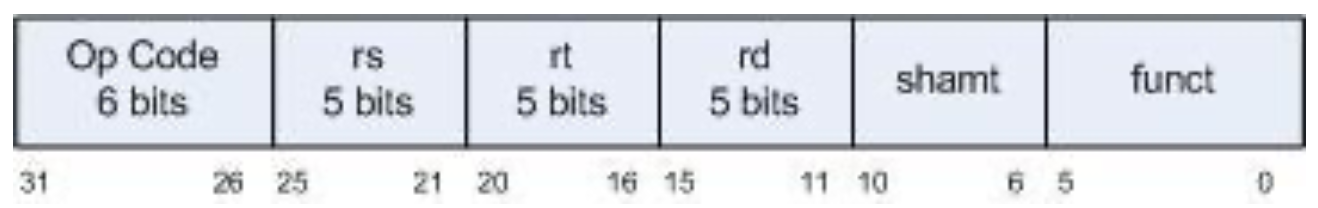
The R format instruction is used when the input values to the ALU come from two registers.
The I format instruction is used when the input values to the ALU come from one register and an immediate value.
The fields in these instructions are as follows:
- Op-code - a 6 bit code which specifies the operation. These codes can be found for each instruction on the MIPS Green Sheet found at:
freepdfs.net/mips-green-sheet...a2139f5cd8d64/.
Op-codes these are stored as a 2 digit number. The first number is 2 bits wide, and has values from 0-2. The second number is 4 bits wide, and has values from 0x0 to 0xf. So for example the
lwinstruction has an op code of 23, or 1000112. Theaddihas an op code of 8, or 001000 (if the first digit is not specified, it is zero).All R-format operators have an op-code of 0, and are specified as an op-code/function. So the
addop-code is specified by an op-code/function of 0/20. The operation to be performed by the ALU is contained in the function, which is the last field in the R instruction. Functions, like op-codes, are specified as a 2 bit number and a 4 bit number. - rs - This is the first register in the instruction, and is always an input to the ALU. Note that rs, rt, and rd are 5 bits wide, which allows the addressing of the 32 general purpose registers.
- rt - This is the second register in the instruction. It is the second input to the ALU when there is an rd specified in the instruction (as in ADD) and the destination register when rd is not specified in the instruction (as in ADDI)
- rd - rd always is the destination register when it is specified.
- shamt - The number of bits to shift if the operation is a shift operation, otherwise it is 0.
It is 5 bits wide, which allows for shifting of all 32 bits in the register.
- funct - For an R type instruction, this specifies the operation for the ALU.
- immediate - The immediate value for instructions which use immediate values.
In MARS the machine code which is generated from the assembly code is shown in the Code column, as in figure 4-3. A good way to check if you have translated your code correctly is to see if your translation matches the code in this column.
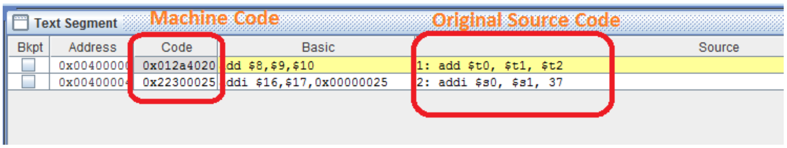
The rest of the sections of this chapter are intended to help makes sense of this machine code.