
6.2: Static Data
- Page ID
- 27128

Static data 19 is data that is defined when the program is assembled, and allocated when the program starts to run. Due to the fact that it is allocated once, the size and location of static data is fixed and cannot be changed. If a static array is allocated with 10 members, it cannot be resized to have 20 members. A string of 21 characters can never be more than 21 characters. In addition all variables which will be defined as static must be known before the program is run. These limitations make static data much less useful than stack dynamic and heap dynamic data, which will be covered later.
Static data is defined using the .data assembler directive. All memory allocated in the program in a .data segment is static data. The static data (or simply data) segment of memory is the portion of memory starting at address 0x10000000 and continuing until address 0x10040000. The data elements that are defined come into existence when the program is started, and remain until it is completed. So while the data values can change during the course of a program execution, the data size and address does not change.
When the assembler starts to execute, it keeps track of the next address available in the data segment. Initially the value of the next available slot in the data segment is set to 0x10010000. As space is allocated in the data segment, the next available slot is incremented by the amount of space requested. This allows the assembler to keep track of where to store the next data item. For example, consider the following MIPS code fragment.
.data
a: .word 0x1234567
   .space 14
b: .word 0xFEDCBA98
If this is the first .data directive found, the address to start placing data is 0x10010000. A word is 4 bytes of memory, so the label a: points to a 4 byte allocation of memory at address 0x10010000 and extending to 0x10010003, and the next free address in the data segment is updated to be 0x10010004.
Next an area of memory is allocated that using the .space 14 assembly directive. The .space directive sets aside 14 bytes of memory, starting at 0x10010004 and extending to 0x10010011. There is no label on this part of the data segment, which means that the programmer must access it directly through an address. This is perfectly valid, but is really not that useful, especially when there are multiple .data directives used, as it is hard for a programmer to keep track of the next address. Generally there will be a label present for variables in the data segment.
Finally another word of memory is allocated at the label b:. This memory could have been placed at 0x10010012 (1810), as this is the next available byte. However specifying that this data item is a word means that it must be placed on a word boundary. Remember that words are more than just 32 bits (4 bytes) in MIPS. Words are successive groups of 4 bytes. Words are thus allocated on addresses which are divisible by 4. If the next available address is not on a word boundary when a word allocation is asked for, the assembler moves to the next word boundary, and the space between is simply lost to the program.
The following MARS screen shows the what the memory looks like after assembling this code fragment.
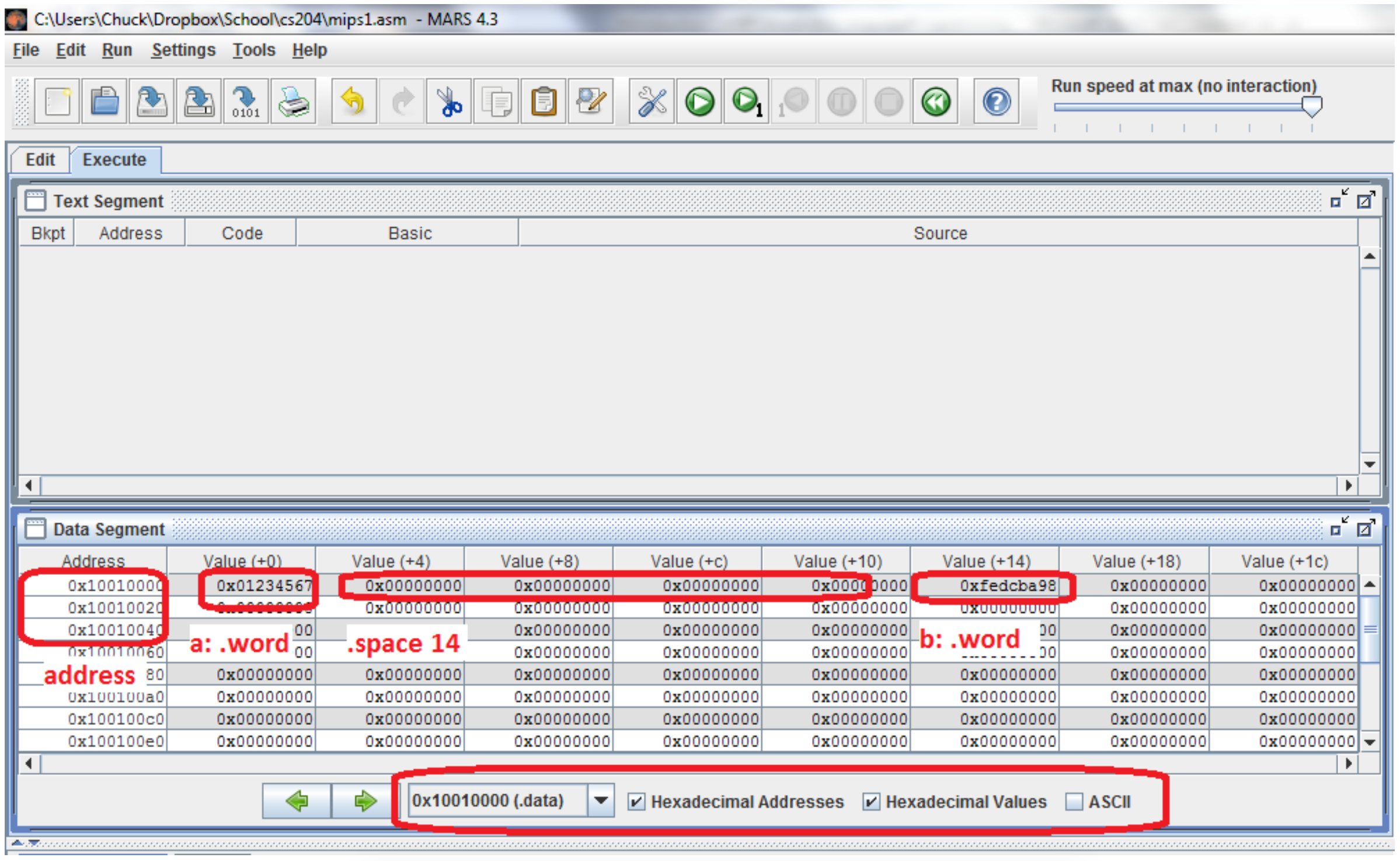
This image shows the contents of the data segment of memory for the previous code fragment. Note the dropdown menu at the bottom of the screen that says the memory being viewed is the "0x1001000(.data)" segment. Other portions of memory can be viewed, but for now we will limit the discussions to the data segment.
This image shows there are a number of options for showing the values of the addresses and memory. The first check box, labeled "Hexadecimal Addresses", allows memory addresses can be shown in hex or decimal. The checkbox labeled "Hexadecimal Values" allows all memory and register values in the entire screen to be displayed in either hex or decimal, and is useful when looking for data values which the programmer knows in decimal. Finally the "ASCII" checkbox allows the data in the memory to be displayed as ASCII characters when appropriate. It is useful when looking for ASCII strings in memory.
To read the memory contents in the image, look at the column called address, and 8 columns after it. The column address gives the base address for a grouping of 32 (0x20) byte addresses. So the top row in this table is addresses starting at 0x1001 0000 and extending to 0x1001 001f, the second row is addresses starting at 0x1001 0020 and extending to 0x1001 003f, and so on. Each subsequent column is the 4 bytes (or word) offset from the base address. The first column is the base address + 0 bytes, so it is addresses 0x1001 0000 - 0x1001 0003, the second column is addresses 0x1001 0004 - 0x1001 0007, and so on. From this image we can see that the memory at label a: stores 0x01234567, then 14 bytes of uninitialized memory are allocated, the next two bytes of memory are unused and lost, and finally a word at label b: which stores 0xfedcba98. This is what the assembly code had specified.
One last note about the memory. In HLL, memory always had a context. Memory was always a type, such as a string, or an integer, or a float, and so forth. In assembly there is no context maintained with the memory, so it is really just a collection of bits. The context of the memory is the operations that the programmer performs on it. This is very powerful, but it is hard to keep track of and very error prone. One of the biggest skills a programmer can learn by doing assembly is to be careful, and always keep track of the data in the program. In assembly language, there is no type definitions or predefined contexts for variables to keep a programmer from really messing up a program.
19 Static is not used here in the same way as it is used in Java or C#. In these languages, static means classwide, or one per class. Static variables are associated with the class, not an instance of the class, and static methods cannot access instance variables. The original meaning of static came to these languages from C, where static is used in the same way as it is used here in assembler. There is no relationship between the Java or C# use of static, and static memory.