
11.6: UML class diagrams
- Page ID
- 12797

One challenge of working with the code in this chapter is that we have several classes that depend on each other. Here are some of the relationships between the classes:
- MyLinearMap contains a LinkedList and implements Map.
- MyBetterMap contains many MyLinearMap objects and implements Map.
- MyHashMap extends MyBetterMap, so it also contains MyLinearMap objects, and it implements Map.
- MyFixedHashMap extends MyHashMap and implements Map.
To help keep track of relationships like these, software engineers often use UML class diagrams. UML stands for Unified Modeling Language (see thinkdast.com/uml). A “class diagram” is one of several graphical standards defined by UML.
In a class diagram, each class is represented by a box, and relationships be- tween classes are represented by arrows. Figure \(\PageIndex{1}\) shows a UML class diagram for the classes from the previous exercise, generated using the online tool yUML at http://yuml.me/.
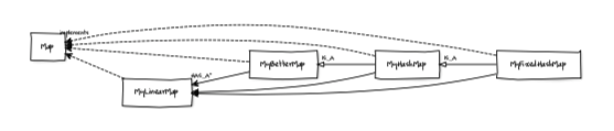
Figure \(\PageIndex{1}\): UML diagram for the classes in this chapter.
Different relationships are represented by different arrows:
- Arrows with a solid head indicate HAS-A relationships. For example, each instance of MyBetterMap contains multiple instances of MyLinearMap, so they are connected by a solid arrow.
- Arrows with a hollow head and a solid line indicate IS-A relationships. For example, MyHashMap extends MyBetterMap, so they are connected by an IS-A arrow.
- Arrows with a hollow head and a dashed line indicate that a class implements an interface; in this diagram, every class implements Map.
UML class diagrams provide a concise way to represent a lot of information about a collection of classes. They are used during design phases to communicate about alternative designs, during implementation phases to maintain a shared mental map of the project, and during deployment to document the design.