
2.2: Capacitors
- Page ID
- 18944

Material Polarization
When an external voltage is applied across an insulator, charges separate throughout the material, and this charge separation is called a material polarization. Material polarization can be defined more precisely in terms of the electric field intensity \(\overrightarrow{E}\) and the displacement flux density \(\overrightarrow{D}\), two vector fields which show up in Maxwell's equations, Equations 1.6.3 - 1.6.6. These vector fields are related by \[\overrightarrow{D} = \epsilon \overrightarrow{E}. \nonumber \]
Why do we define two electric field parameters when they are just scaled versions of each other? It is useful to separate the description of the electric field inside a material from the description of the field in free space. Similarly, two vector fields describe magnetic field, the magnetic field intensity \(\overrightarrow{H}\) and magnetic flux density \(\overrightarrow{B}\), and these fields show up in Maxwell's equations for the same reason. Material polarization, \(\overrightarrow{P}\) in units \(\frac{C}{m^2}\), is defined as the difference between the electric field in the material \(\overrightarrow{D}\) and the electric field that would be present in free space \(\overrightarrow{E}\). More specifically \[\overrightarrow{P} =\overrightarrow{D}-\epsilon_0 \overrightarrow{E} \nonumber \] or \[\overrightarrow{P} =(\epsilon - \epsilon_0) \overrightarrow{E}. \nonumber \]
These expressions involve the permittivity of free space \(\epsilon_0\) and the permittivity of a material \(\epsilon\) which were defined in Electromagnetic Waves and Materials.
Scientists overload both the words capacitance and polarization with multiple meanings. See Appendix C for more details on the different uses of these terms.
Energy Storage in Capacitors
When a capacitor is charged, energy is converted from electrical energy to energy stored in a material polarization which is energy of the charge separation. When it is discharged, energy is converted from energy stored in the material polarization back to electrical energy of flowing electrons. Capacitors are made from an insulating material between conducting plates. As we supply a voltage across the insulator, charges accumulate on the plates. The voltage built up is proportional to the charge accumulated on the plates. \[Q =Cv \label{2.2.4} \]
In Equation \ref{2.2.4}, \(Q\) is the charge in coulombs, \(v\) is the voltage, and the constant of proportionality is the capacitance \(C\) in farads. If we take the derivative with respect to time, we get the more familiar expression relating the current and voltage across the capacitor. \[\frac{dQ}{dt} =i =C\frac{dv}{dt} \nonumber \]
The capacitance of a capacitor is related to the permittivity of the dielectric material between the conductors. Permittivity is a measure of the amount of energy that can be stored by a dielectric material. As described by Equation 1.6.20, for a parallel plate capacitor this relationship is \[C =\frac{\epsilon A}{d_{thick}} \label{2.2.6} \]
where \(A\) is the area of the plates and \(d_{thick}\) is the distance between the plates. The energy \(E\) stored in a capacitor as a function of voltage applied across it is given by\[E =\frac{1}{2}Cv^2 =\frac{1}{2}Qv. \nonumber \]
The capacitance of a vacuum-filled parallel plate capacitor is described by Equation \ref{2.2.6} with permittivity \(\epsilon = \epsilon_0\), the permittivity of free space. As we charge the capacitor, charges accumulate on the plates, and no change occurs to the vacuum between the plates. If we replace the vacuum with a dielectric with \(\epsilon > \epsilon_0\), the capacitance becomes larger. The dielectric filled capacitor can store more energy, all else equal, because the dielectric material changes as the capacitor charges. More specifically, the material polarizes. In an insulator, electrons are bound to their atoms, and current cannot flow. Instead, the electrons in a dielectric move slightly with respect to their nuclei while still staying bound to the atoms. Electrons are always in motion for materials at temperatures above absolute zero, but when a material polarizes, the net location of electrons with respect to the nuclei changes. As the capacitor charges, the electrons are slightly displaced from their atoms, balancing the charges on the plates, and more energy is stored in the dielectric for a given voltage. We say that this process induces electric dipoles. The larger the permittivity, \(\epsilon\), the more the material can store energy by polarizing in this way. For this reason, capacitors are often filled with dielectric materials like tantalum dioxide \(Ta_2O_5\) which has \(\epsilon = 25\epsilon_0\) [18]. A material with \(\epsilon = 25\epsilon_0\), for example, will be able to store 25 times the energy of an air filled capacitor of the same size with the same applied voltage.
Permittivity and Related Measures
For historical reasons, the permittivity may be expressed by different measures. The electric susceptibility \(\chi_e\), relative permittivity \(\epsilon_r\), index of refraction \(n\), and permittivity \(\epsilon\) all describe the ability of a material to store energy in the electric field. Electric susceptibility is a unitless measure related to the permittivity by \[\chi_e = \frac{\epsilon}{\epsilon_0}-1 \nonumber \]
and relative permittivity is another unitless measure defined by \[\epsilon_r = \frac{\epsilon}{\epsilon_0}. \nonumber \]
With some algebra, we can write the material polarization in terms of the relative permittivity or the electric susceptibility. \[\overrightarrow{P} =(\epsilon_r-1)\epsilon_0\overrightarrow{E} =\epsilon_0\chi_e\overrightarrow{E} \nonumber \]
Scientists studying optics often use index of refraction, another unitless measure which represents the ratio of the speed of light in free space to the speed of light in the material. \[n =\frac{c}{|\overrightarrow{v}|} = \frac{\text{speed of light in free space}}{\text{speed of light in material}} \nonumber \]
Since electromagnetic waves cannot travel faster than the speed of light in free space, index of refraction of a material is greater than one, \(n > 1\). Assuming a material is a good insulator and \(\mu =\mu_0\), which are typically safe assumption for optics, the relationship between index of refraction and permittivity simplifies to \[n =\sqrt{\epsilon_r}. \nonumber \]
Table \(\PageIndex{1}\) lists relative permittivities of some insulators used to make capacitors or piezoelectric devices. The values are all approximates. See the references cited for more detailed information.
In the definitions of 1.6.3 and in Table \(\PageIndex{1}\), permittivity is treated as a scalar constant, but in some contexts a more complicated description is needed. In a crystalline material, a voltage applied along one crystallographic axis may induce charge separation throughout the material more easily than a voltage of the same size applied along a different axis.
| Material | Relative permittivity \(\epsilon_r\) | Reference |
|---|---|---|
| Vacuum | 1.0 | [3] |
| Teflon | 2.1 | [3] |
| Polyethylene | 2.3 | [3] |
| Paper | 3.0 | [3] |
| \(\text{SiO}_2\) | 3.5 | [18] |
| Mica | 6.0 |
[3] |
| \(\text{Al}_2\text{O}_3\) | 9 | [18] |
| \(\text{AlP}\) | 10.2 | [9] |
| \(\text{ZrSiO}_4\) | 12.5 | [19] |
| \(\text{Si}\) | 11.8 | [9] |
| \(\text{Ge}\) | 16 | [9] |
| \(\text{Ta}_2\text{O}_5\) | 24 | [20] |
| \(\text{ZrO}_2\) | 25 | [18] |
| \(\text{HfO}_2\) | 40 | [18] |
| \(\text{TiO}_2\) | 50 | [18] |
| \(\text{PbS}\) | 161 | [9] |
| \(\text{PbSe}\) | 280 | [9] |
| \(\text{BaSrTiO}_3\) | 300 | [18] |
| \(\text{PbTe}\) | 360 | [9] |
In such cases, the material is called anisotropic. Permittivity of anisotropic materials is more accurately described by a matrix.
\[ \begin{pmatrix} \epsilon_{xx} & \epsilon_{xy} & \epsilon_{xz} \\ \epsilon_{yx} & \epsilon_{yy} & \epsilon_{yz} \\ \epsilon_{zx} & \epsilon_{zy} & \epsilon_{zz} \end{pmatrix} \nonumber \]
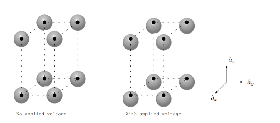
The left part of Figure \(\PageIndex{1}\) shows some atoms of a crystal. The small black circles represent the location of the nuclei of atoms in the crystals, and the gray circles represent the electron cloud surrounding the nuclei of each atom. If an electric field is applied in the \(\hat{a}_z\) direction, the material polarizes, so the electrons are slightly displaced with respect to the nuclei as shown in the figure on the right. Since the spacing of atoms is different in the \(\hat{a}_x\) and \(\hat{a}_y\) direction than the \(\hat{a}_z\) direction, the external field required to get the same charge displacement will be different in the \(\hat{a}_x\) and \(\hat{a}_y\) directions than the \(\hat{a}_z\) direction for this material. For this reason, the material illustrated in the figure is anisotropic, and the permittivity is best described by a matrix as opposed to a scalar quantity.
Capacitor Properties
Capacitors are energy conversion devices used in applications from stabilizing power supplies, to filtering communication signals, to separating out a DC offset from an AC signal. Though capacitors and batteries both store electrical energy, energy in batteries is stored in the chemical bonds of atoms of the electrodes while energy is stored in capacitors in the material polarization from bound charges shifting in a dielectric layer.
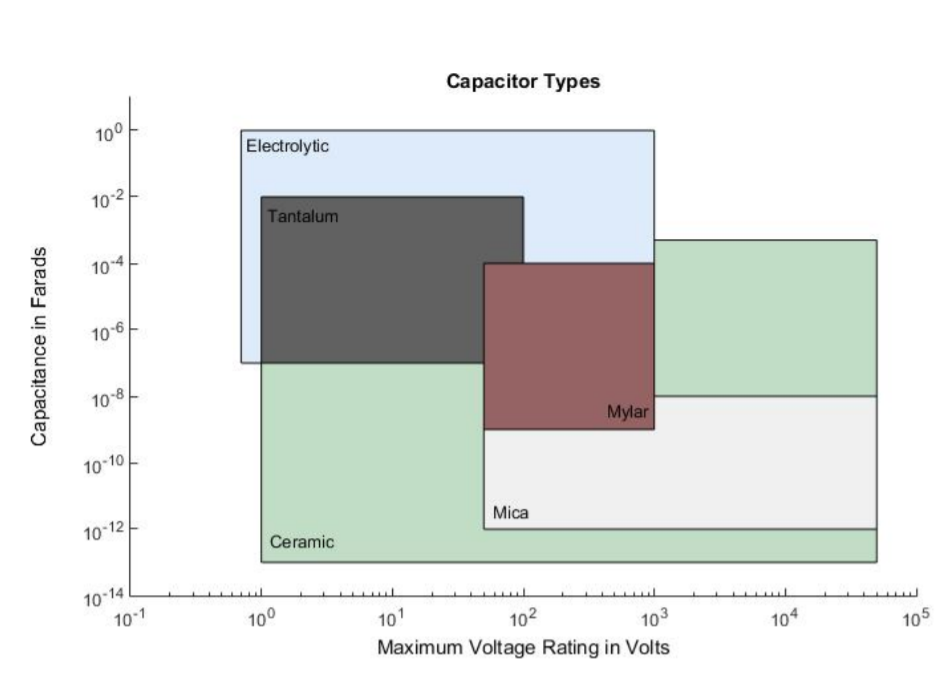
The first two measures to consider when selecting a capacitor to use in a circuit are the capacitance and the maximum voltage. A capacitor can be damaged if it is placed in a circuit where the voltage across it exceeds the maximum rated value. Approximate ranges for these parameters for capacitors with different dielectric materials are shown in Figure \(\PageIndex{2}\). Capacitance ranges are on the vertical axis, and maximum voltage ranges are on the horizontal axis. For example, electrolytic capacitors often can be found with capacitance values ranging from \(10^{-7}\) to 1 F and maximum voltage ratings in the range of 1 to 1000 V. Similarly, ceramic capacitors can often be found with capacitance values ranging from \(10^{-13}\) to \(5 \cdot 10^{-4}\) F and maximum voltage ratings in the range of 1 to 50,000 V.
While capacitance and maximum voltage rating are important parameters to consider, they are not the only considerations. Another factor to consider is temperature stability. Ideally, the capacitance will be independent of temperature. However, all materials have a nonzero temperature coefficient. Ceramic and electrolytic capacitors tend to be more sensitive to temperature variation than polymer or vacuum capacitors [22]. Accuracy, or precision, is also important. Just as resistors are labeled with tolerances, capacitors may have tolerances of, for example, \(\pm5\%\) or \(\pm10\%\). Another factor to consider is equivalent series resistance [23, ch. 1]. All materials have some resistivity, so all capacitors have some finite resistance. To account for the internal resistance, we can model any physical capacitor as an ideal capacitor in series with an ideal resistor, and the value of the resistor used is called the equivalent series resistance. Also, leakage of a capacitor should be considered [22]. If a capacitor is able to retain its stored charge for a long period of time, the capacitor has small leakage. If the capacitor discharges quickly even when disconnected from a circuit, it has large leakage. An ideal capacitor has no leakage [22]. Capacitors are also differentiated by their lifetime. An ideal capacitor operates for decades without degradation. However, some types of capacitors, such as electrolytic capacitors, are not designed to have long lifetimes [22]. Other factors to consider include cost, availability, size, and frequency response [22].
Ceramics, glasses, polymers, and other materials are used as the dielectric [22]. Often capacitors are classied by the dielectric material they contain [22]. Ceramic capacitors are small, cheap, and readily available [22]. They can often tolerate large applied voltages [22]. They typically have small capacitance values, poor accuracy, poor temperature stability and moderate leakage [22]. They have low equivalent series resistance and can withstand a lot of current, but they can cause transient voltage spikes, [23, ch. 1]. Some ceramic capacitors are piezoelectric. If these capacitors are vibrated, or even tapped with a pencil, noise will be introduced in the circuit due to piezoelectricity [23, ch. 12].
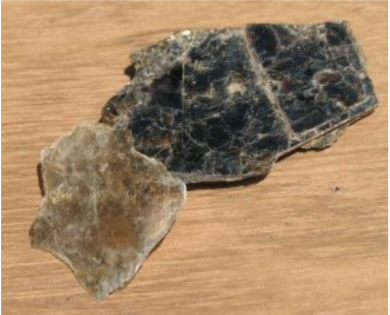
Mica is an interesting material which is used as a dielectric in capacitors. Figure \(\PageIndex{3}\) shows naturally occurring mica collected at Ruggles Mine near Grafton, New Hampshire. Mica comes in different natural forms including biotite and muscovite \(\text{KAl}_2(\text{AlSi}_3\text{O}_{10})(\text{OH})_2\) [24]. Mica is a flaky mineral with a layered structure [24], so mica capacitors can be made with very thin dielectric layers. Mica capacitors often have good accuracy and small leakage [22].
Capacitor dielectrics have been made from many types of polymers including polystyrene, polycarbonate, polyester, polypropylene, Teflon, and mylar [22]. These capacitors often have good accuracy, temperature stability, and leakage characteristics [22].
Not all capacitors have solid dielectrics. A vacuum is a dielectric. Capacitors with a vacuum dielectric are used in applications which involve high voltage or which require very low leakage [22]. Capacitors with liquid dielectrics made of oil are used in similar situations [22]. Electrolytic capacitors often have dielectrics which are a combination of solid materials with liquid electrolytes. An electrolyte is a liquid through which some charges can ow more easily than others. Electrolytic capacitors are polarized, meaning that they have positive and negative terminals, so, similar to a diode, the orientation of the capacitor in a circuit is important. Inside an electrolytic capacitor is a junction of multiple materials. The initial application of voltage in the factory chemically creates an oxide layer which is the dielectric. Reversing the voltage will dissolve the dielectric and destroy the capacitor. One advantage of electrolytic capacitors is that a small device can have a large capacitance. However, they often have poor accuracy, temperature stability, and leakage [22]. Also, electrolytic capacitors have a finite lifetime because the liquid can degrade over time.