
9.3: Charge Flow in Batteries and Fuel Cells
- Page ID
- 18993

Battery Components
The flow of both positive and negative charges must be considered to understand the operations of batteries and fuel cells. The simplest battery contains just an anode, cathode, and electrolyte. These components are illustrated in Fig. \(\PageIndex{1}\).
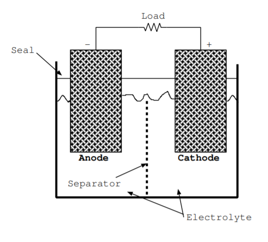
Both of the electrodes must be good conductors. They are often porous to increase the surface area where the reaction occurs. The cathode is a sink for electrons and positive ions, and both of these types of charges are attracted towards this terminal. The cathode is the positive electrode of a discharging battery. The anode is source for electrons and positive ions, and both of these types of charges flow away from the anode. The anode is the negative electrode of a discharging battery.
The electrolyte has high ionic conductivity but low electrical conductivity. For this reason, during discharge of a battery, ions flow from the anode to the cathode through the electrolyte. Meanwhile, electrons are forced to flow from the anode to the cathode through the load. The electrolyte is often a liquid but sometimes a thin solid. Batteries are contained in a package. If the electrolyte is liquid, a seal is included to prevent it from spilling or escaping [140]. Most batteries also contain a separator, which is typically made from a thin polymer membrane [140].
The separator allows some but not other ions to flow through, and it is a physical barrier that prevents the electrodes from contacting and shorting out the battery.
| Battery components | Optional components for protection |
|---|---|
| Anode | Diode |
| Cathode | Fuse or circuit breaker |
| Electrolyte | Vent |
| Separator | Microcontroller |
| Seal | Thermocouple |
Additional components are often added to improve device safety, and Table \(\PageIndex{1}\) lists some of these optional components. A user may mistakenly insert a battery backwards. To prevent damage due to this error, some batteries incorporate a diode [128, ch. 5.1]. The voltage across the terminals of a battery with an internal diode will necessarily be less than the voltage across an equivalent battery without the diode present. Other batteries, like typical 9V batteries, incorporate connectors that can only be attached one way. A battery may also be damaged if the terminals are shorted. Most batteries include vents so gases can safely escape when a battery is damaged due to shorting the terminals, attempting too much current draw, or overheating for other reasons [128, ch. 5.1]. Some batteries include a fuse or circuit breaker in the package to prevent damage in these cases too. Additionally, rechargeable batteries can be damaged if the recharging process is not properly controlled [128, ch. 5.1]. Some rechargeable batteries have a thermocouple and microcontroller built into the package to control the recharging process and prevent overheating during recharging [128, ch. 5.1]. Users should not try to recharge nonrechargeable batteries. While the chemical reaction can often go in either direction, the package and structure of a primary battery are not designed to withstand the charging process and will typically be damaged [128, ch. 5.1].
Charge Flow in a Discharging Battery
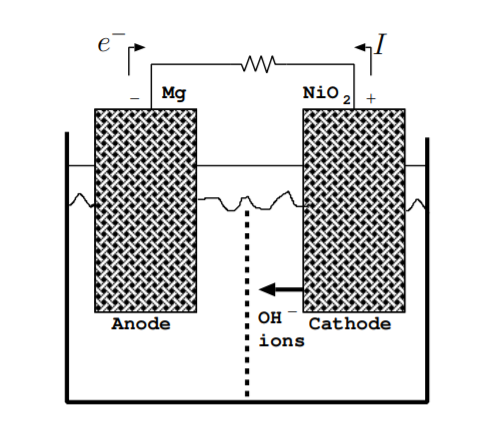
As a battery discharges, chemical energy stored in the bonds holding together the electrodes is converted to electrical energy in the form of current flowing through the load. Consider an example battery with a magnesium anode and a nickel oxide cathode. The reaction at the anode is given by
\[\mathrm{Mg}+2 \mathrm{OH}^{-} \rightarrow \mathrm{Mg}(\mathrm{OH})_{2}+2 e^{-} \label{9.3.1} \]
which has a redox potential of \(V_{rp} = 2.68\) V [137] [140]. The reaction at the cathode is given by
\[\mathrm{NiO}_{2}+2 \mathrm{H}_{2} \mathrm{O}+2 e^{-} \rightarrow \mathrm{Ni}(\mathrm{OH})_{2}+2 \mathrm{OH}^{-} \label{9.3.2} \]
which has a redox potential of \(V_{rp} = 0.49\) V [140]. The overall reaction is given by
\[\mathrm{Mg}+\mathrm{NiO}_{2}+2 \mathrm{H}_{2} \mathrm{O} \rightarrow \mathrm{Mg}(\mathrm{OH})_{2}+\mathrm{Ni}(\mathrm{OH})_{2} \nonumber \]
This reaction occurs in alkaline solutions that contain OH\(^-\) ions available to react, so an electrolyte such as potassium hydroxide, KOH, can be used [140]. Other reactions may simultaneously occur at these electrodes [137], but for simplicity these other reactions will be ignored.
Figure \(\PageIndex{2}\) illustrates the charge flow in the battery during normal operation. A complete circuit is formed not just by the flow of electrons but by a combination of the flow of electrons and ions [128]. Electrons flow away from the negative terminal (anode) through the load. Negative OH\(^-\) ions flow away from the positive terminal (cathode) through the electrolyte. The separator should allow the OH\(^-\) to flow from the positive terminal to the negative terminal. For some electrodes, though not in this example, positive ions, instead of negative ions, complete the circuit by flowing away from the negative terminal. As shown in the figure, the direction of current flow is opposite to the direction of electron flow. The battery continues to discharge until one of the electrodes is used up [3, p. 226].
Charge Flow in a Charging Battery
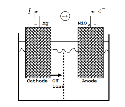
Figure \(\PageIndex{3}\) illustrates the flow of charges when the battery is charging. During charging, energy is converted from electrical energy due to the external voltage source back to chemical energy stored in the chemical bonds holding together the electrodes. Again, the flow of both electrons and ions, not just electrons, must be considered. As above, the direction of the current is the opposite of the direction of the flow of electrons. Reactions occurring are the opposite of the reactions given by Equations \ref{9.3.1} and \ref{9.3.2}. By definition, the cathode is the electrode which electrons flow towards, and the anode is the electrode which electrons flow away from. During charging, unlike during discharging, the cathode is the negative terminal and the anode is the positive terminal. For this example, the reaction at the cathode is
\[\mathrm{Mg}(\mathrm{OH})_{2}+2 e^{-} \rightarrow \mathrm{Mg}+2 \mathrm{OH}^{-} \nonumber \]
and the reaction at the anode is
\[\mathrm{Ni}(\mathrm{OH})_{2}+2 \mathrm{OH}^{-} \rightarrow \mathrm{NiO}_{2}+2 \mathrm{H}_{2} \mathrm{O}+2 e^{-}. \nonumber \]
In this example, OH\(^-\) ions flow away from the cathode during charging. However, in some reactions, both the flow of negative ions away from the cathode and positive ions away from the anode must be considered during charging.
Charge Flow in Fuel Cells
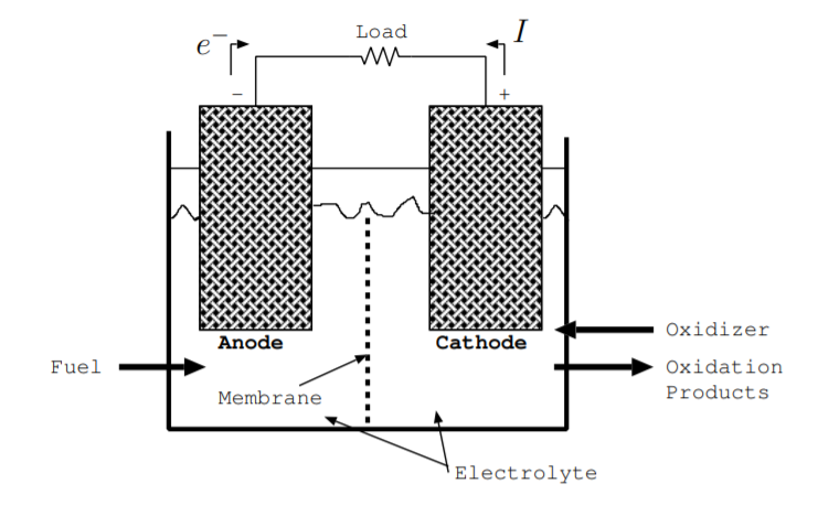
A fuel cell contains many of the same components as a battery [3, p. 226] [128, p. 376] [141]. Like a battery, a fuel cell contains an anode and a cathode. These electrodes must be good conductors, and they are often porous so that they have a large surface area. Electrodes are in a liquid or solid electrolyte through which ions can flow. The electrodes are often coated in a catalyst, such as platinum, to speed up chemical reactions [141]. A fuel cell contains a separator, typically called a membrane, which selectively allows ions to flow. As with the separator of a battery, it is typically made from a thin polymer. Fuel is added at the anode, and an oxidizer is added at the cathode. Typically, both the fuel and oxidizer are liquids or gases. They get consumed during operation while the anode and cathode are not consumed as they are in a discharging battery. These components are illustrated in Fig. \(\PageIndex{4}\).
As an example, a fuel cell may use H\(_2\) gas as the fuel and O\(_2\) gas as the oxidizer. The anode may be carbon cloth [141], and this reaction is sped up by a platinum catalyst [108]. An alkaline solution such as KOH can be the electrolyte. For this fuel in an alkaline electrolyte, the reaction at the anode is
\[\mathrm{H}_{2}+2 \mathrm{OH}^{-} \rightarrow 2 \mathrm{H}_{2} \mathrm{O}+2 e^{-} \nonumber \]
and the reaction at the cathode is
\[\frac{1}{2} \mathrm{O}_{2}+2 e^{-}+\mathrm{H}_{2} \mathrm{O} \rightarrow 2 \mathrm{OH}^{-} \nonumber \]
Figure \(\PageIndex{4}\) also illustrates charge flow in an example fuel cell [3, p. 226] [128, p. 376] [141]. Oxidation, the process of ripping electrons off the fuel leaving positive ions, occurs at the anode. These electrons flow from the anode to the cathode through the load. At the cathode, the oxidizer is reduced. In other words, at the cathode, the oxidizer reacts incorporating these electrons to form negative ions. These negative ions flow from the cathode to the anode, and positive ions flow from the anode to the cathode. The membrane prevents charges from flowing in the reverse direction, and it prevents the positive ions and negative ions from combining with each other directly. A fuel cell can continue to operate as long as the fuel and oxidizer are added and the oxidation products are removed.