
11.13: Ferrite Components- Circulators and Isolators
- Page ID
- 41347

Circulators and isolators are nonreciprocal devices that preferentially route microwave signals. The essential element is a disc (puck) of ferrite which when magnetized supports a preferred direction of propagation due to the gyromagnetic effect.
11.8.1 Gyromagnetic Effect
An electron has a quantum mechanical property called spin (there is not a spinning electron) creating a magnetic moment \(m\), see Figure \(\PageIndex{1}\)(a). In most materials the electron spin occurs in pairs with the magnetic moment of one electron canceled by the oppositely-directed magnetic moment of an other electron. However, in some materials the spin does not occur in pairs and there is a net magnetic moment.
A most interesting microwave property occurs when a magnetic material is biased by a DC magnetic field resulting in the gyromagnetic effect. This affects the way an RF field propagates and this is described by a nine element permeability called a tensor. The permeability of a magnetically biased magnetic material is:
\[\label{eq:1}\left[\mu\right]=\left[\begin{array}{ccc}{\mu_{xx}}&{\mu_{xy}}&{\mu_{xz}}\\{\mu_{yx}}&{\mu_{yy}}&{\mu_{yz}}\\{\mu_{zx}}&{\mu_{zy}}&{\mu_{zz}}\end{array}\right]=\left[\begin{array}{ccc}{\mu_{0}}&{0}&{0}\\{0}&{\mu}&{\jmath\kappa}\\{0}&{-\jmath\kappa}&{\mu}\end{array}\right] \]
That is,
\[\label{eq:2}\left[\begin{array}{c}{B_{x}}\\{B_{y}}\\{B_{z}}\end{array}\right]=\left[\begin{array}{ccc}{\mu_{0}}&{0}&{0}\\{0}&{\mu}&{\jmath\kappa}\\{0}&{-\jmath\kappa}&{\mu}\end{array}\right]\left[\begin{array}{c}{H_{x}}\\{H_{y}}\\{H_{z}}\end{array}\right] \]
Thus a \(z\)-directed \(H\) field produces a \(y\)-directed \(B\) field. The effect on propagation of an EM field is shown in Figure \(\PageIndex{1}\)(b). The EM wave does not travel in a straight line and instead curves, in this case, to the right. Thus forward- and backward-traveling waves diverge from each other and propagation is not reciprocal. This separates forward- and backward-traveling waves.
11.8.2 Circulator
A circulator exploits the gyromagnetic effect. Referring to the schematic of a circulator shown in Figure \(\PageIndex{2}\)(a), where the arrows indicate that the signal that enters Port \(1\) of the circulator leaves the circulator at Port \(2\) and not at Port \(3\). Similarly power that enters at Port \(2\) is routed to Port \(3\), and
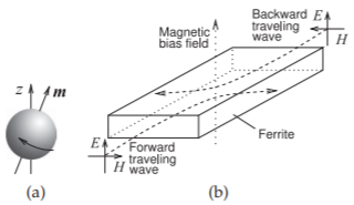
Figure \(\PageIndex{1}\): Magnetic moments: (a) electron spin; and (b) Gyromagnetic effect impact on the propagation of EM waves in a magnetic material with an externally applied magnetic bias field.
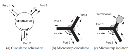
Figure \(\PageIndex{2}\): Ferrite components with a magnetized ferrite puck in the center in (b) and (c).
power entering at Port \(3\) is routed to Port \(1\). In terms of \(S\) parameters, an ideal circulator has the scattering matrix
\[\label{eq:3}\mathbf{S}=\left[\begin{array}{ccc}{0}&{0}&{S_{13}}\\{S_{21}}&{0}&{0}\\{0}&{S_{32}}&{0}\end{array}\right]=\left[\begin{array}{ccc}{0}&{0}&{1}\\{1}&{0}&{0}\\{0}&{1}&{0}\end{array}\right] \]
A microstrip circulator is shown in Figure \(\PageIndex{2}\)(b), where a disc of magnetized ferrite can be placed on top of a microstrip Y junction to realize a preferential direction of propagation of the EM fields. In the absence of the biasing magnetic field, the circulation function does not occur.
11.8.3 Circulator Isolation
The isolation of a circulator is the insertion loss from what is the output port to the input port, i.e. in the reverse direction. Referring to the circulator in Figure \(\PageIndex{2}\)(a), if port \(1\) is the input port there are two output ports and so there are two isolations equal to the return loss from port \(3\) to port \(2\), and from port \(2\) to port \(1\). The smaller of these is the quoted isolation. If this is an ideal circulator and port \(2\) is perfectly matched, then the isolation would be infinite. Then the \(S\) parameters of the circulator are
\[\label{eq:4}\mathbf{S}=\left[\begin{array}{ccc}{\Gamma}&{\alpha}&{T}\\{T}&{\Gamma}&{\alpha}\\{\alpha}&{T}&{\Gamma}\end{array}\right]\approx\left[\begin{array}{ccc}{0}&{0}&{1}\\{1}&{0}&{0}\\{0}&{1}&{0}\end{array}\right] \]
where \(T\) is the transmission factor, \(\Gamma\) is the reflection coefficient at the ports, and \(\alpha\) is the leakage.
11.8.4 Isolator
Isolators are devices that allow power flow in only one direction. Figures \(\PageIndex{2}\)(c) and \(\PageIndex{3}\) show microstrip isolators based on three-port circulators. Power entering Port \(1\) as a traveling wave is transferred to the ferrite and emerges at Port \(2\). Virtually none of the power emerges at Port \(3\). A traveling wave signal applied at Port \(2\) appears at Port \(3\), where it is absorbed in a termination created by resistive material placed on top of the microstrip. The resistive material forms a lossy transmission line and no power is reflected. Thus power can travel from Port \(1\) to Port \(2\), but not in the reverse direction.
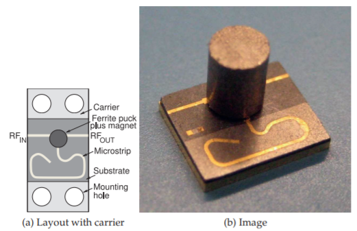
Figure \(\PageIndex{3}\): A microstrip isolator operating from \(29\) to \(31.5\text{ GHz}\). Isolator in (b) has the dimensions \(5\text{ mm}\times 6\text{ mm}\) and is \(6\text{ mm}\) high. The isolator supports \(2\text{ W}\) of forward and reverse power with an isolation of \(18\text{ dB}\) and insertion loss of \(1\text{ dB}\). Renaissance 2W9 series, copyright Renaissance Electronics Corporation, used with permission.
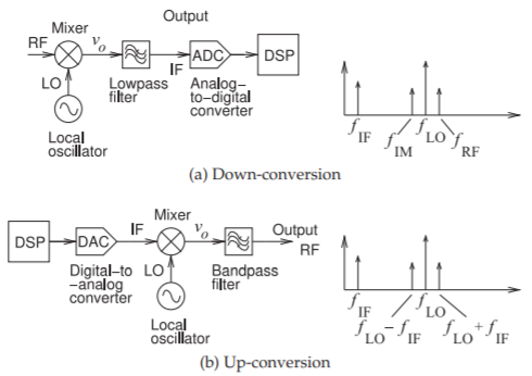
Figure \(\PageIndex{4}\): Frequency conversion using a mixer.