
8.2: Debouncing
- Page ID
- 25726

Real world mechanical switches do not behave ideally. When a switch is thrown, the mechanical contacts bounce after the initial closure resulting in a series of make-break contacts. This might last for 10 milliseconds or more depending on the design of the switch. Examples of switch bounce are shown in Figure \(\PageIndex{1}\). The problem is that the microcontroller can read the input pin in a fraction of a millisecond, and therefore, it appears as if the switch is being thrown on and off very rapidly during this multi-millisecond stretch. In some applications this is not a problem, for example, when an LED is activated according to switch position (i.e. “up” or “depressed” lights the LED). In this instance, the bounce or chatter of the signal and the LED will not be noticed by the human eye. In contrast, we might program a button switch so that multiple pushes increase a level such as brightness or volume. In this case the chatter might cause a series of levels to be skipped over yielding an inconsistent and quirky response to user input.
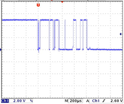
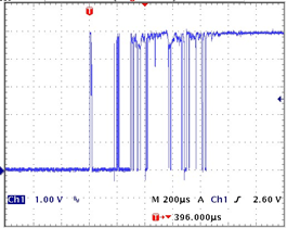
Figure \(\PageIndex{1}\): Switch bounce
There are two basic ways of “debouncing” switches. The first involves software and the second involves hardware. Let’s look at a software solution first.
The key to a software debounce is to stretch out the time the switch is being examined. In other words, we want to examine the state over a long enough period of time that the bouncing settles out. For example, if we note that the state has not changed over the course of, say, ten milliseconds, we can safely assume we’re not trying to read the input during a bounce. Consider the code variant below. It looks a lot like version three but there is a new function added, get_state(). This is where all the action is.
/* Read Digital Input V4. Monitors Arduino pin 8 and sends value to the
Serial Monitor, generic form, only reports state changes, with software
debounce */

// new function prototype
int get_state(void);

// Arduino pin 8 is port bit B.0
#define BITMASK 0x01

int priorstate=0;

void setup()
{
      Serial.begin(9600);

      DDRB &= (~BITMASK);     // initialize the pin as an input.
      PORTB |= BITMASK;       // enable pull-up
}
void loop()
{
      int state;

      state = get_state();

      if( state != priorstate )
      {
            Serial.println(state);
            priorstate = state;
      }
}

int get_state(void)
{
      int priorstate, state, count=0, i=0;

      priorstate = PINB & BITMASK;

      while( i < 30 )
      {
            state = PINB & BITMASK;

            if( state == priorstate )
                  count++;
            else
            {
                  count = 0;
                  priorstate = state;
            }

            if( count >= 10 )
                  break;

            delay(1);
            i++;
      }
      return( state );
}
The idea behind this new function is to continually check the pin and not return until we have seen ten milliseconds worth of consistent values. Every time the current state is the same as the prior state we increment count. When it hits 10 we know we have achieved at least ten milliseconds of unchanging signal (due to the one millisecond delay() call at the bottom of the loop), we break out of the loop and return the pin state. If levels shift due to bounce, state and priorstate will not be the same so count is reset. If a switch is faulty, the bounce period could last a very long time and to prevent the code from “hanging up” and staying in this function forever, a maximum number of 30 iterations (at least 30 milliseconds) is instituted via the variable i.
Enter version four and save it under a new name as we’ll be coming back to version three a little later. Compile and transfer the code, and then test it using the Serial Monitor. This version should produce a nice, consistent output on the Serial Monitor without the extraneous transitions of version three. It’s also worth noting that the resultant machine code is still smaller than the original code made with the Arduino libraries in spite of greater functionality (2654 bytes versus 2726 bytes for version one).
The second method to debounce a switch is via hardware. Generally, this takes the form of the switch being connected to an RC network which feeds a Schmitt Trigger (74HC14). The RC network will effectively filter the chattering signal and the hysteresis of the Schmitt will take care of any lingering noise or fluctuation. Figure \(\PageIndex{2}\) is a typical example (note the switch logic is reversed due to the inverter):
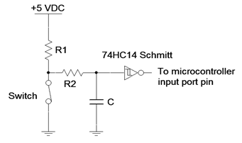
Figure \(\PageIndex{2}\): RC-Schmitt Trigger debounce circuit
Typical values for this circuit would be 4.7 k\(\Omega\) for R1, 470 k\(\Omega\) for R2 and 100 nF for C. The RC time constant for this circuit is roughly 50 milliseconds so the Schmitt thresholds will be reached in around 200 milliseconds (less than 5 \(\tau\)). This should take care of even the crankiest mechanical switch. Also, note that this is an active input signal so the input pull-up will not be needed. Let’s go back to version three (without software debounce) and make a modification to accommodate the hardware debounce:
/* Read Digital Input V5. Monitors Arduino pin 8 and sends value to the
Serial Monitor, generic form, only reports state changes, requires hardware
debounce to drive the input */

// Arduino pin 8 is port bit B.0
#define BITMASK 0x01

int priorstate=0;

void setup()
{
      Serial.begin(9600);

      DDRB &= (~BITMASK);     // initialize the pin as an input.
      // pull-up code has been removed
}

void loop()
{
      int state;

      state = PINB & BITMASK;

      if( state != priorstate )
      {
            Serial.println(state);
            priorstate = state;
      }
}
Remove the hardware switch from the board. Build the debounce circuit from Figure \(\PageIndex{2}\) and connect its output to Arduino pin 8. Compile and transfer the code. Open the Serial Monitor and test the results. It should be similar to that of version four with software debounce. Also note that the code is about 300 bytes smaller. We have effectively traded memory for hardware.
There are some nice advantages to software debounce compared to hardware debounce. First, it is very flexible in that the code can be changed to fine tune the performance. Second, there’s no associated cost for the additional hardware components or expanded board space to accommodate them. There are some disadvantages, though, including increased code memory requirements for the debouncing functions (remember, microncontrollers, unlike PCs, tend to have very modest memory capacity). Another issue is the time wasted waiting for the switch signal to settle. Ten or twenty milliseconds may not seem like a lot but in some applications it can be an eternity. Whether software or hardware debounce will be used for a particular design; indeed, whether debounce will be used at all, will depend on other system factors.
Obviously, monitoring the pin state with the Serial Monitor tool is very useful for debugging and learning how the device works but it is not a typical application so let’s move to something a little more useful. Instead of sending output to the serial monitor, let’s reflect the state using an external LED off of Arduino pin 12, i.e., bit 4 of port B. We’ll continue to use the hardware debounce circuit with the new code below:
/* Read Digital Input V6. Monitors Arduino pin 8 and reflects value to an
external LED, generic form, requires hardware debounce to drive the input */

// Arduino pin 8 is port bit B.0
#define BITMASK 0x01

// Place LED driver on Arduino pin 12 or port bit B.4
#define LEDMASK 0x10

int priorstate=0;

void setup()
{
      DDRB &= (~BITMASK);     // initialize the pin as an input from 74HC14
      DDRB |= LEDMASK;        // initialize the pin as an output to the LED
}

void loop()
{
      int state;

      state = PINB & BITMASK;

      if( state != priorstate ) // don’t bother if no change
      {
            priorstate = state;

            if( state )
                  PORTB |= LEDMASK;       // light LED
            else
                  PORTB &= (~LEDMASK);    // extinguish LED
      }
}
Build a standard LED driver circuit (NPN and PNP versions shown in Figure \(\PageIndex{3}\)) and connect it to Arduino pin 12. Determine a value for Rc to achieve about 10 milliamps of LED current assuming the LED voltage is 2 volts. Set Rb to achieve a base current of around 500 microamps.
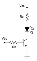
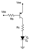
Figure \(\PageIndex{3}\): LED Driver Circuits
Once the hardware is in place; enter, compile and transfer the code. The LED should reflect your switch position. Also, if you haven’t already noticed, look at the status bar on the editor. Because we are no longer using the Serial Monitor and its associated library, the code size has dropped to a mere 510 bytes!