
1.2: Component Identification
- Page ID
- 26039

In this lab, many different electronic components are used including passive devices such as resistors and capacitors as well as semiconductors such as diodes and transistors, and finally, integrated circuits. These devices are available in many different case styles. Two broad classifications are through-hole and surface mount. As circuits will be built on protoboards, through-hole components are of particular interest here. Surface mount devices are generally smaller and use thin flat tabs or stubs in place of ordinary wire leads. In production they are soldered directly to the surface of the printed circuit board without the use of holes.
1.2.1: Resistors and Potentiometers
Resistors are perhaps the single most common component. They are classified as passive devices (versus active devices AKA semiconductors). Resistors have two leads and are not directional so they cannot be inserted backwards. Leads are usually axial (i.e., emanating from opposite ends). The physical size of a resistor indicates its power handling capacity, not its resistance. The general purpose lab resistor is usually a carbon film type, 1/4 watt dissipation. Resistance values are shown via a color coded series of bands for most types, although high precision resistors may have the value printed directly on the body.
Potentiometers may be either rotary or linear travel (slider), with rotary being the most common. Most rotary pots are 3/4 turn, although precision trim pots may be 20 turns or more. Typically, the center of the three connections is the wiper arm. Rotary pots may be designed for panel mount (for example, a volume control on a stereo) or board mount (such as a calibration control). The taper of a pot indicates how resistance and position are related. Pots may have a linear taper or a specialized audio taper (log taper). A linear taper means that a specific degree of rotation will produce the same resistance change. Rotating the shaft half way, for example, results in a 50/50 split of the resistance. In contrast, an audio taper pot would show a 10/90 split. Pots are also available in multi-gang, that is, several pots controlled by one common shaft.
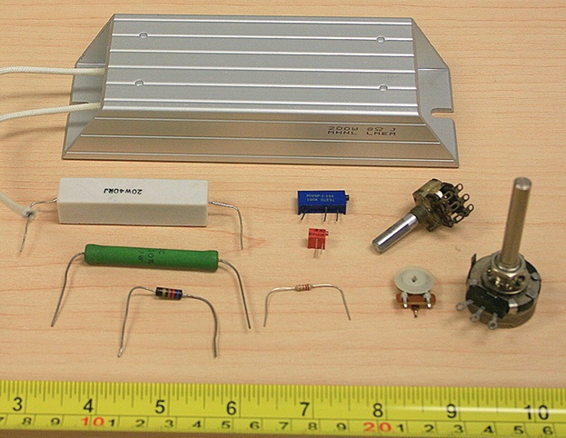
Figure \(\PageIndex{1}\): Resistors and Potentiometers Capacitors
1.2.2: Capacitors
are also classified as passives and can be though of as very short term energy storage devices. Capacitors are dual lead but may have either axial or radial (radiating from one end) leads. Unlike resistors, the physical size of a capacitor offers a clue as to its capacitance and voltage rating. All other factors being equal the greater the capacitance or voltage rating, the larger the capacitor. Most smaller capacitors (below 1 \(\mu\)F) are not polarized and can be inserted into a circuit either way. The more popular dielectrics for this range include the ceramics (usually disk or coin shaped) and poly film types (polyester, polypropylene, etc.) which are usually block shaped. Teardrop shaped tantalum capacitors are used commonly for power supply bypass. They are polarized and must be inserted in the circuit in the specified direction. Larger capacitance values (over 1 \(\mu\)F) are often realized via aluminum electrolytics. These are also polarized. Failure to insert these in the proper direction may result in unpredictable results, including the capacitor exploding. While they do not perform as well as film types in terms of leakage, accuracy, etc., they are offer high volumetric efficiency (i.e., small physical size given the capacitance). Very large caps may have screw terminals in place of wire leads. In years past, color coding was common but this has generally been replaced with values printed directly on the body of the capacitor. Sometimes a numeric code is used such as “102”. This is read as 10 followed by 2 zeroes, with the result in picofarads, or 1000 pF (1 nF) in this case. Finally, because capacitors are charge storage devices, they may present a shock hazard from stored charge after they are removed from a circuit. This charge may be bled off with a low value resistance placed across the leads.
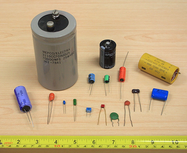
Figure \(\PageIndex{2}\): Capacitors
1.2.3: Inductors
The third and final passive device is the inductor. Also non-polarized, they normally have axial leads. Smaller values may be completely encapsulated and appear not much different from a carbon composition resistor. Others may use some form of jacket or coating while still others show bare wire (the wire only appears bare, it is in fact covered by a thin clear insulating coating). These vary from the size of small resistors to what appear to be large spools of wire.
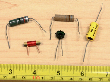
Figure \(\PageIndex{3}\): Inductors
1.2.4: Diodes
Diodes are a two lead semiconductor. They are polarized and typically have axial leads. The two leads are referred to as the anode and cathode. Signal diodes are around the size of 1/4 watt resistors and sometimes use a glass body. The cathode is marked by a band or stripe on the body of the diode. The cathode of an LED is usually marked by a flat spot on the plastic housing or by the shorter of the two leads. High power diodes are much more robust and might appear at first glance to be a short bolt or stud with leads attached to it. Component numbers are usually stamped on the body of the device.
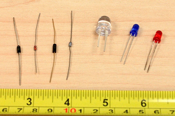
Figure \(\PageIndex{4}\): Diodes
1.2.5: Transistors
There are many types of transistors. Generally, they are three lead devices. Component model numbers will be stamped directly onto the case. Small power dissipation (< 500 mW) units will usually be seen in plastic TO-92 cases, round metal TO-5 cans or variations on the theme. Mid power devices typically use TO-220, TO-202 or the like “power tab” cases. For higher powers the oval TO-3 cases are employed. A similarly shaped but slightly smaller variant is the TO-66. Power devices will need to use a heat sink to keep them cool. TO-92 cases use a flattened front face so that the three pins may be distinguished from each other without confusion. The round TO-5 can uses a small tab to indicate pin 1.
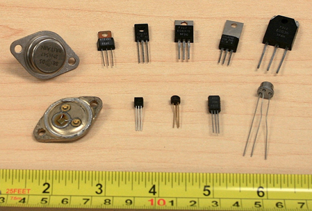
Figure \(\PageIndex{5}\): Transistors
1.2.6: Integrated Circuits
There are a very wide variety of integrated circuits. Multi-lead versions of the TO-5 can are sometimes used but the most common through-hole package is the Dual In-Line Package, denoted as DIP or DIL. A single in-line package is also available for some functions. High power devices often use multi-lead versions of the popular TO-220 and TO-3 case styles. Like other semiconductors, component model numbers are printed directly on the package. A notch or dimple will denote which lead is pin 1 on the DIP/DIL cases.
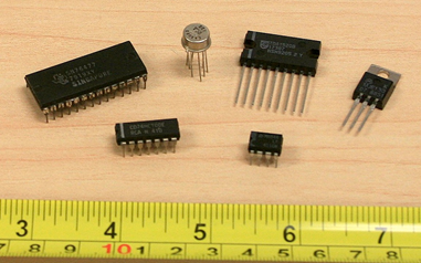
Figure \(\PageIndex{6}\): Integrated Circuits
1.2.7: Transformers
Transformers can vary from tiny audio devices to room size devices used in power generation and distribution. No matter the size, their job is a simple one: to isolate the source and load, to match two different impedance devices or to change the voltage level. A very common application is stepping down a 120 VAC line voltage to a more modest level so that it can be rectified, filtered, and turned into a stable DC source to drive electronic circuits. Besides the voltage turns ratio, the most important characteristic is the VA or volt-amps rating of the device. All other factors being equal, the higher the VA rating, the larger the transformer. Transformers applicable for consumer electronics may be either chassis mount with leads or PCB mount with through-hole pins. Transformers only operate with AC voltages.
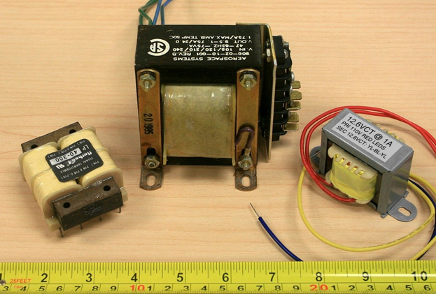
Figure \(\PageIndex{7}\): Transformers
1.2.8: Heat Sinks
Heat sinks are not a device, per se, but they are essential tools of semiconductor heat management. Their job is to effectively move heat from the semiconductor’s case to the surrounding air, keeping the semiconductor cool. They range in size from small clip-ons to large extruded aluminum finned plates. Some cases, such as the body of the TO-3 or the tab of the TO-220 are electrically live. To prevent possible shorts and a live chassis, non-conductive isolating tabs and grommets are used to attach the semiconductors to the heat sink.
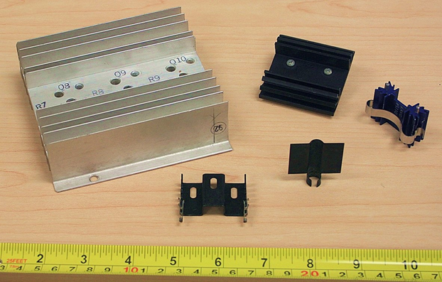
Figure \(\PageIndex{8}\): Heat Sinks