
9.6: Exercises
- Page ID
- 25298

Unless specified otherwise, assume generator frequencies are 60 Hz for all problems.
Analysis
1. As depicted in Figure \(\PageIndex{1}\), a three-phase delta-connected generator feeds a delta-connected load. The generator phase voltage is 120 volts and the load consists of three legs of 10 \(\Omega\) each. Find the voltage across each load leg, the line current through the wires connecting the load to to the generator and the power drawn by the load.
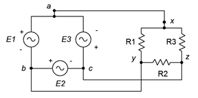
Figure \(\PageIndex{1}\)
2. Referring to the delta-delta system of Figure \(\PageIndex{1}\), if the generator phase voltage is 230 volts and the load is balanced with each leg at 2 \(\Omega\), determine the line voltage, line current, generator phase current and load current.
3. The system of Figure \(\PageIndex{2}\) shows a three-phase Y-connected generator feeding a Y-connected load. If the generator phase voltage is 120 volts and the load consists of three legs of 20 \(\Omega\) each, find the line voltage, the line current, voltage across each load leg and the total power drawn by the load.
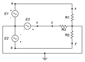
Figure \(\PageIndex{2}\)
4. Referring to Figure \(\PageIndex{2}\), if the generator phase voltage is 230 volts and the load is balanced with each leg at 12 \(\Omega\), determine the line voltage, line current, generator phase current, load current, load voltage and total load power.
5. As depicted in Figure \(\PageIndex{3}\), a three-phase delta-connected generator feeds a Y-connected load. The generator phase voltage is 120 volts and the load consists of balanced legs of 5 \(\Omega\) each. Find the voltage across each load leg, the line current, the line voltage, the generator phase current and the total load power.
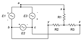
Figure \(\PageIndex{3}\)
6. Referring to Figure \(\PageIndex{3}\), if the generator phase voltage is 400 volts and the load is balanced with each leg at 10 \(\Omega\), determine the line voltage, line current, generator phase current, load current and the voltage across each load leg.
7. The system of Figure \(\PageIndex{4}\) shows a three-phase Y-connected generator feeding a delta-connected load. If the generator phase voltage is 120 volts and the load consists of three legs of 60 \(\Omega\) each, find the line voltage, the line current, voltage across each load leg and the total power drawn by the load.
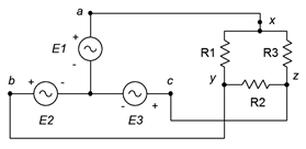
Figure \(\PageIndex{4}\)
8. Referring to the Y-delta system of Figure \(\PageIndex{3}\), if the generator phase voltage is 120 volts and the load is balanced with each leg at 20 \(\Omega\), determine the line voltage, line current, generator phase current, load current, the voltage across each load leg and the total load power.
9. A three-phase delta-connected generator feeds a delta-connected load consisting of three legs of 10 \(\Omega\) in series with \(j4\) \(\Omega\) of inductive reactance, as shown in Figure \(\PageIndex{5}\). If the line voltage is 208 volts, find the voltage across each load leg, the current through the wires connecting the load to to the generator, and the apparent and real powers drawn by the load.
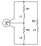
Figure \(\PageIndex{5}\)
10. Given the delta-delta system of Figure \(\PageIndex{5}\), if the generator phase voltage is 120 volts and the load is balanced with each leg at \(20 + j10\) \(\Omega\), determine the line voltage, line current, generator phase current, load current, the voltage across each load leg, and the total real and apparent load powers.
11. A three-phase Y-connected generator feeds a Y-connected load consisting of three legs of 10 \(\Omega\) in series with \(j4\) \(\Omega\) of inductive reactance, as shown in Figure \(\PageIndex{6}\). If the line voltage is 208 volts, find the voltage across each load leg, the line current, and the apparent and real powers drawn by the load.
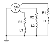
Figure \(\PageIndex{6}\)
12. Given the Y-Y system of Figure \(\PageIndex{6}\), if the line voltage is 400 volts and the load is balanced with each leg at \(100 + j20\) \(\Omega\), determine the generator phase voltage, line current, generator phase current, load current, the voltage across each load leg, and the total real and apparent load powers.
13. The three-phase system of Figure 9.3.3 uses a Y-connected generator feeding a delta-connected load. The load consists of three legs of 40 \(\Omega\) in series with \(j30\) \(\Omega\) of inductive reactance, as shown in Figure 9.32. If the generator phase voltage is 230 volts, find the line voltage, the voltage across each load leg, the line current, the load current, and the apparent and real powers drawn by the load.
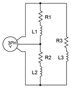
Figure \(\PageIndex{7}\)
14. Given the Y-delta system of Figure \(\PageIndex{7}\), if the line voltage is 400 volts and the load is balanced with each leg at \(80 + j20\) \(\Omega\), determine the generator phase voltage, line current, generator phase current, load current, the voltage across each load leg, and the total real and apparent load powers.
15. A 208 three-phase delta-connected generator feeds a Y-connected load consisting of three legs of 10 \(\Omega\) in series with \(j4\) \(\Omega\) of inductive reactance as shown in Figure \(\PageIndex{8}\). Find the voltage across each load leg, the current through the wires connecting the load to to the generator, and the apparent and real powers drawn by the load.
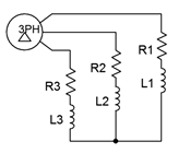
Figure \(\PageIndex{8}\)
16. Given the delta-Y system of Figure \(\PageIndex{8}\), if the line voltage is 400 volts and the load is balanced with each leg at \(120 + j30\) \(\Omega\), determine the line current, generator phase current, load current, the voltage across each load leg, and the total real and apparent load powers.
17. A 120 volt three-phase delta-connected generator feeds a delta-connected load consisting of three legs of 75 \(\Omega\) in series with \(−j10\) \(\Omega\) of capacitive reactance as shown in Figure \(\PageIndex{9}\). Find the voltage across each load leg, the current through the wires connecting the load to to the generator, and the apparent and real powers drawn by the load.
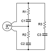
Figure \(\PageIndex{9}\)
18. A three-phase Y-connected generator feeds a Y-connected load consisting of three legs of 150 \(\Omega\) in series with \(−j20\) \(\Omega\) of capacitive reactance as shown in Figure \(\PageIndex{10}\). If the generator phase voltage is 120 volts, find the line voltage, the voltage across each load leg, the line current, and the apparent and real powers drawn by the load.
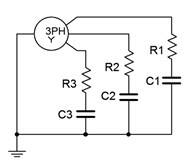
Figure \(\PageIndex{10}\)
Design
19. Using the delta-delta system of problem 9 and assuming the source frequency is 60 Hz, determine appropriate component values to place in parallel with each load leg in order to shift the power factor to unity.
20. Using the Y-Y system of problem 11 and assuming the source frequency is 60 Hz, determine appropriate component values to place in parallel with each load leg in order to shift the power factor to unity.
Challenge
21. Using the Y-Y system of problem 11 and assuming the source frequency is 60 Hz, determine appropriate component values to be added to the load in order to shift the power factor to unity. These new components should be in a delta configuration.
Simulation
22. Use a transient analysis to verify the phase and line voltage phase relationships in problem 1.
23. Use a transient analysis to verify the results computed for problem 15.
24. Use a transient analysis to verify the design solution to problem 19. This can be achieved by ensuring that the voltage and current in each load leg (with added correction components) are in phase.
25. Use a transient analysis to verify the design solution to problem 20. This can be achieved by ensuring that the voltage and current in each load leg (with added correction components) are in phase.