
3.3: Implementing the Switch Circuit to Turn on a Light
- Page ID
- 26962

In this project you will connect the breadboard to the power supply, then wire the positive and negative side strips. You will then put a switch on the board, and connect the switch to a LED so that the switch can turn the LED on and off. This will complete the project.
\(\PageIndex{1}\) The breadboard
This section describes the breadboard in your lab kits. For more information about breadboards please see the following link:
http://en.Wikipedia.org/wiki/Breadboard
The following is a picture of a typical breadboard:
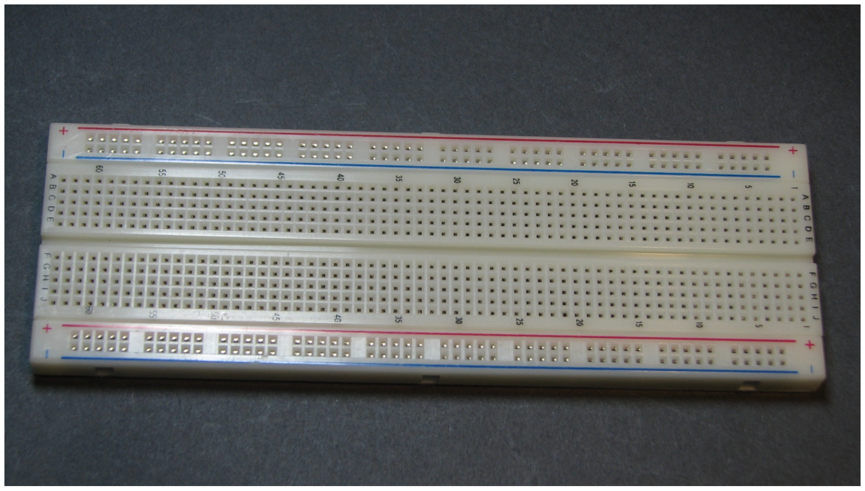
On the breadboard there are two long strips, called rails, running along the side. The red rail is normally connected to a positive (+5 volts) power supply, and the blue rail is normally connected to ground (0 volts). Note that rails must be connected to a battery or other power source to power them.
There are a number of 10 hole rows in the board, separated by a center empty column. In a row, groups of 5 holes on each side of the empty column are connected. There is no connection between the rows.
This wiring of the breadboard is shown in the Figure \(\PageIndex{2}\). For the positive and ground rails a wire runs the length of the board which connects the holes in the positive and negative rails. Note that the rails on opposite sides of the breadboard are not connected. Powering one side of the rails does not power both sides, and the rails must be connected to fully power the board. This will be done as part of the circuit created in this chapter.
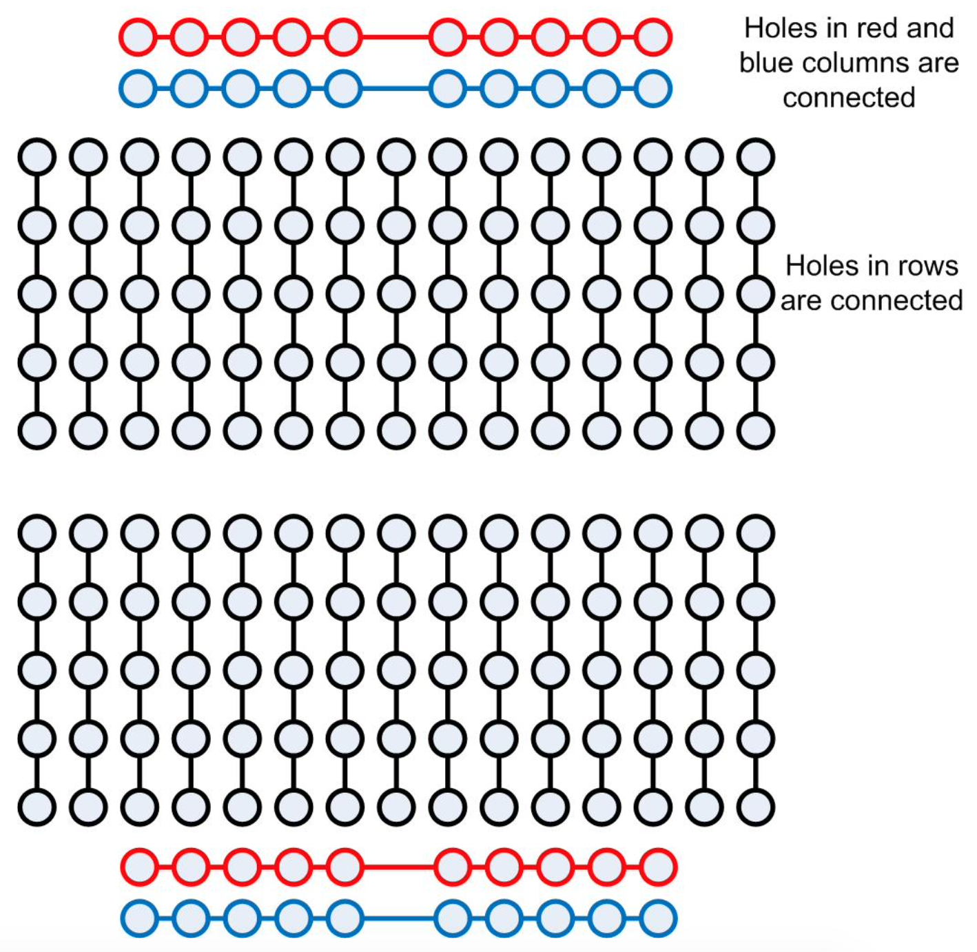
This breadboard layout also shows that the groups of 5 holes in each row are also connected, though the top and bottom groups of 5 holes are not. Normally the holes in these groups of 5 on the two sides of the board will be kept separate. This will make sense when chips are installed and used.
The groups of five holes are numbered 1 to 60 on each side of the breadboard. Each group of five holes are wired together, so two wires which are placed in holes in the same group on a row are connected. This will be used to wire the circuits.
\(\PageIndex{2}\) Stripping wires
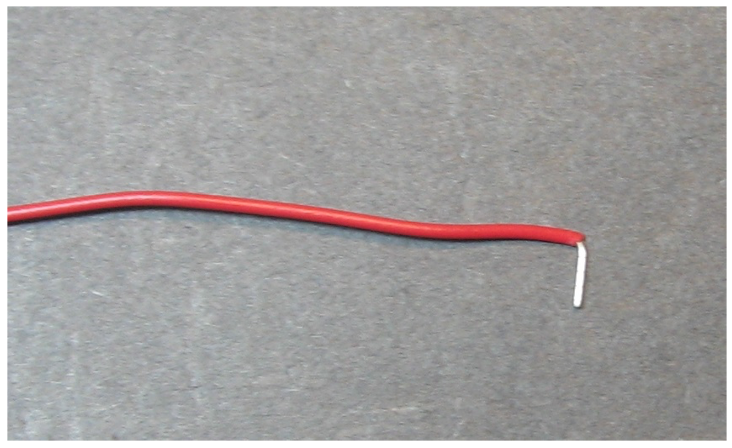
To make contact with the holes in the breadboard, the insulation must be removed from the ends of the wires. To do this wire strippers will be used. Typical wire strippers are shown in the following figure. Wire strippers are sharp and can easily cut the wire we are using here by placing the wire in the lower part of the clippers (1), and closing them. However, the notches in the wire strippers are places where there is a predetermined distance between the two blades which is just the size of the copper wire inside of our insulation. By placing the wire in the notch labeled 22 AWG (or .60 mm) (2), the insulation is cut but the wire is not. Then by simply pulling the wire from the strippers there is a clean end to the wire that no longer is insulated. This is what will be placed in the holes in the breadboard. When stripping the wires, you should strip off about 1/4 to 1/2 an inch of insulation. The holes in the breadboard will grab the wires when they are placed inside and make a good contact. If you strip too little insulation off of the wire the connection to the breadboard will probably be poor, and your circuits will not work. If you strip too much insulation off, the circuit will have the possibility of short circuiting. So strip enough insulation so that the wires are grabbed in the hole, but not too much more.
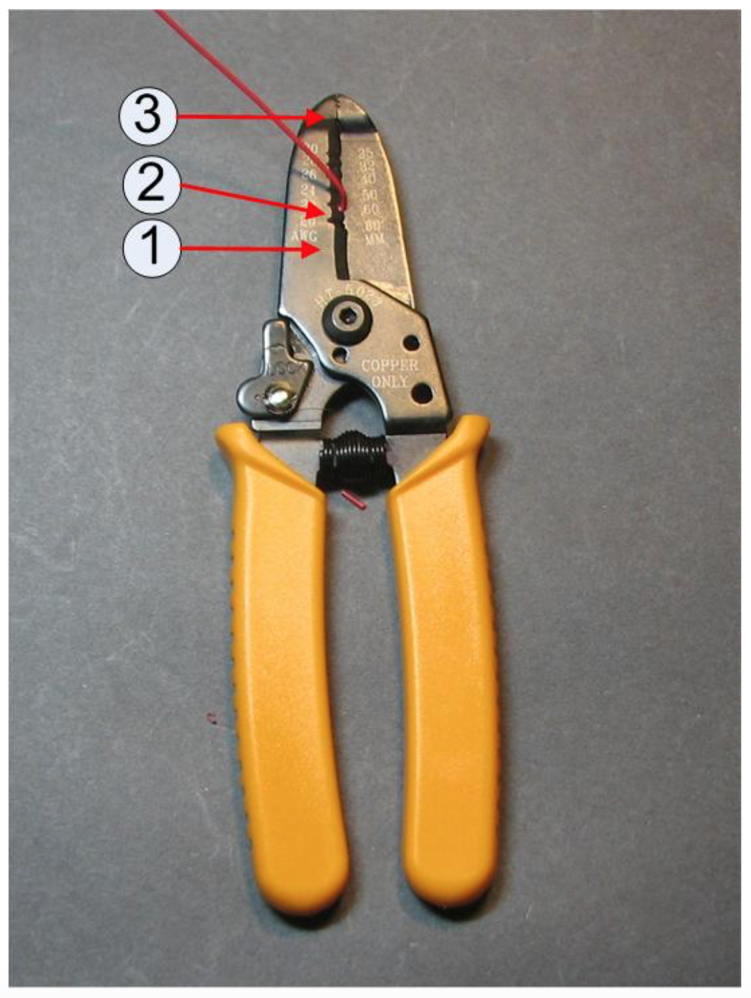
The end of the wire strippers (3) can be used as pliers, and is helpful to bend the end of the wire. This is useful if you implement the circuits so that the wires run flush along the board, as they will do in this book. If you cut your wires very long and run them above the board, as many students do, you do not want to bend the end of the wire. Running wires flush along the board makes the circuit neater and easier to read, but it makes the circuit harder to wire, and takes much more time to implement.
\(\PageIndex{3}\) Powering the Circuit
You are now ready to implement the circuit. The steps in creating the circuit will be as follows.
- Power will be provided to the breadboard.
- A switch will be inserted into the breadboard.
- The output from the switch will be sent to the LED, which will complete the circuit.
The first step is to provide power to the breadboard. Pictures of how to power the breadboard are shown in the Figure \(\PageIndex{6}\) and Figure \(\PageIndex{9}\). These figures contain numbers corresponding to the step-by-step instructions below. As was mentioned earlier, wires in this circuit that always carry a positive voltage are red, ground wires are black, and wires that can take on either value are yellow.
- Find the 7805 voltage regulator (shown in Figure \(\PageIndex{5}\)). The 7805 voltage regulator will take the input of 9 volts from the battery and convert it to 5 volts needed by the chips which will be used in the circuit 5. Place the 7805 voltage regulator so that it straddles rows 1, 2, and 3 on the breadboard as shown in Figure \(\PageIndex{6}\). The fit may be tight, so be careful to push it in gently so as to not bend the legs.
- The input to pin 1 (the pin in row 1 of the breadboard) of the 7805 is the positive 9 volts from the battery. In the figure a red wire is used to indicate this wire is always connected to positive input. Connect a wire to any hole on the first row, leaving one end not connected to anything. This will be connected to the positive lead of the battery when the breadboard is powered. To test if this is correct, connect the long leg of an LED to the positive output of the 7805 regulator, and the short end to the ground, as shown in Figure \(\PageIndex{5}\). Make sure the battery is new and strong, or you might now get power across the 7805 regulator.
Figure \(\PageIndex{5}\): 7805 voltage regulator 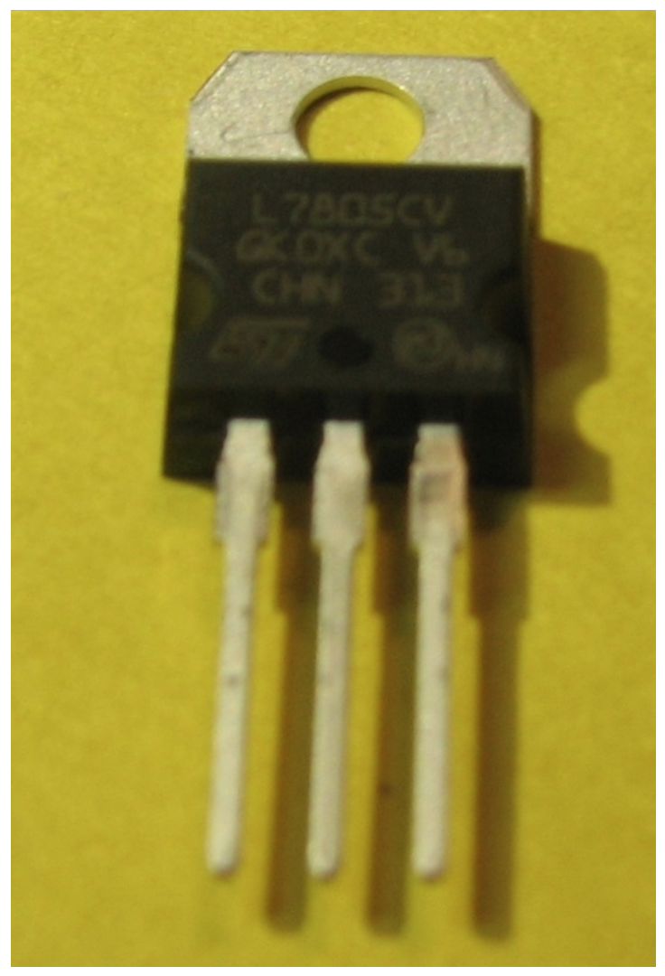
Figure \(\PageIndex{6}\): Powering the breadboard 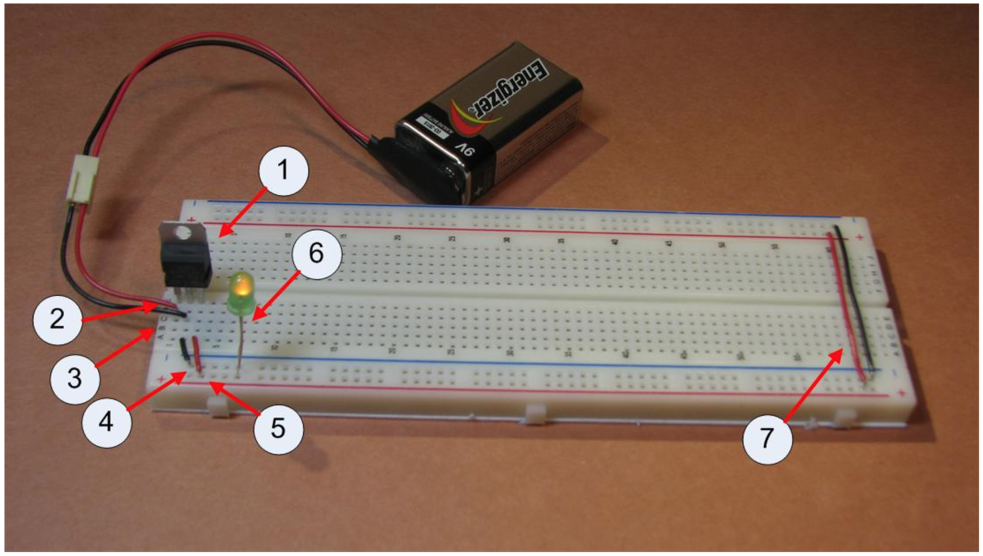
- The input to the 7805 pin 2 (the pin in row 2 of the breadboard) is now connected to the ground coming from the 9 volt battery. In the figure a black wire is used to indicate this is wire is always connected to ground. Connect a wire to any hole on the second row, leaving one end not connected to anything. This will be connected to the negative lead of the battery when the breadboard is powered.
- Connect the ground rail of the breadboard to row 2. The ground rail is the blue column which runs down the side of the board. Note that row 2 has three connections, the input ground from the battery, the middle pin on the 7805 chip, and the output wire to the blue ground side rail.
- The 5 volt output from the 7805 is the pin in row 3. To power the board, connect row 3 to the positive rail of the breadboard. The positive rail is the red column which runs down the side of the board.
- The left half of the board is ready to be connected to the battery. Put a 9 volt battery in the battery snap, and connect the leads from the battery to red and black wires from steps 3 and 4. (Be sure to connect positive wire to positive input, and negative wire to negative input!) The board should now have power. This can be checked by placing an LED between the positive and negative rails on the board. Note that the LED has two legs, and one is longer than the other, as shown in Figure \(\PageIndex{7}\). Make sure to place the positive (long) leg in the positive (red) rail, and the short leg in the ground (blue) rail. The light should come on. If it does not, you have a debugging problem. Here are some things to try:
- Make sure that the battery is connected correctly, positive to positive and negative to negative. If it is not, your 7805 chip will quickly start to become hot. If this happens, disconnect the battery and allow the chip to cool. When the chip is cool, reconnect the battery correctly.
- Make sure the LED is properly oriented. This simple mistakes often causes confusion, and so when using an LED always make sure to orient it correctly.
- Make sure the battery and the snap are ok by putting the LED directly into the 9 volt battery clip. If the LED lights, move to step d.
- Make sure that current is getting to the board correctly. Connect the battery to your positive and negative leads (to power the board) and place the LED between rows 1 and 2 of the board to make sure that you have a good connection with the leads. If the LED lights, move to step e.
- Make sure you have current coming from the 7805 by connecting the LED between rows 3 and 2. If the LED does not light, something is wrong with the 7805. Check that you have installed it correctly (not backwards for instance).
Figure \(\PageIndex{7}\): LED 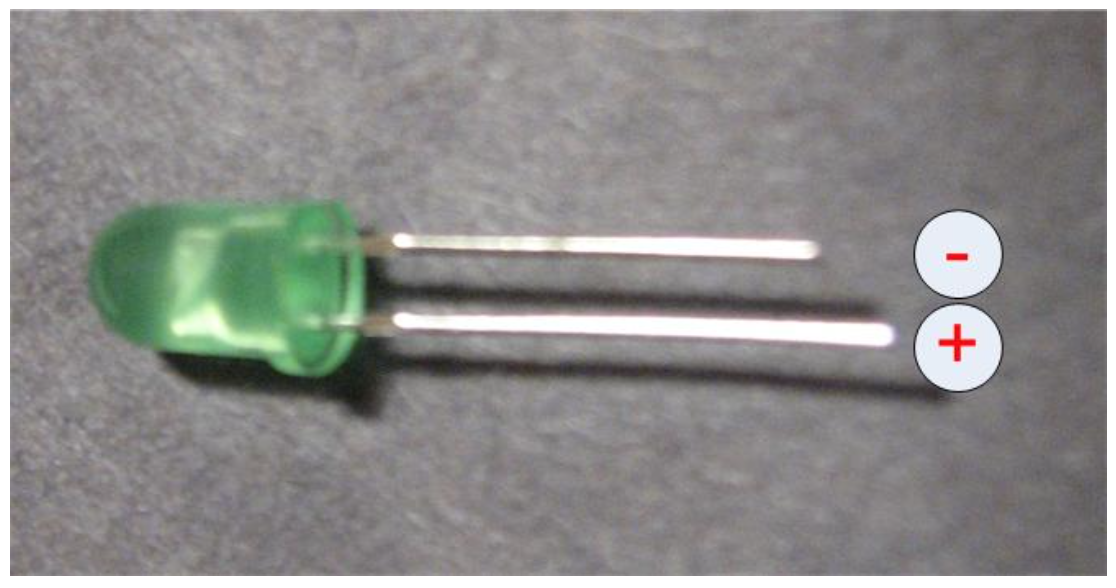
- The left half of the bread board should now have powered, but the right half is still not connected. To connect the right half of the breadboard, go to the last row with the blue and red rails. Run a wire from the left red rail (the outside left rail) to the right red rail (the inside right rail) as shown in Figure \(\PageIndex{6}\). Do the same for the blue rail. This should power the rails on the right side of the breadboard. You can test that both rails are now powered by using the LED between the blue and red rails on the right side of the breadboard as in step 6 above.
The breadboard is now powered.
\(\PageIndex{4}\) Installing the switch
The purpose of this first circuit was to have a switch turn on/off a light. This section will describe how to install the switch. The instructions below refer to Figure \(\PageIndex{9}\).
- The switch to be installed is shown in Figure \(\PageIndex{8}\). There are two nuts and two washers on the switch. These will not be used in the circuits in this book, and make the switch harder to use. Remove them. You may want to save them in case you ever use this switch in a different circuit.
- To install the switch, insert it across 5 rows of the breadboard. In this picture, the switch is placed across rows 9-13. Only the 1st (row 9), 3rd (row 11), and 5th (row 13) rows will be connected to the switch.
Figure \(\PageIndex{8}\): Toggle switch 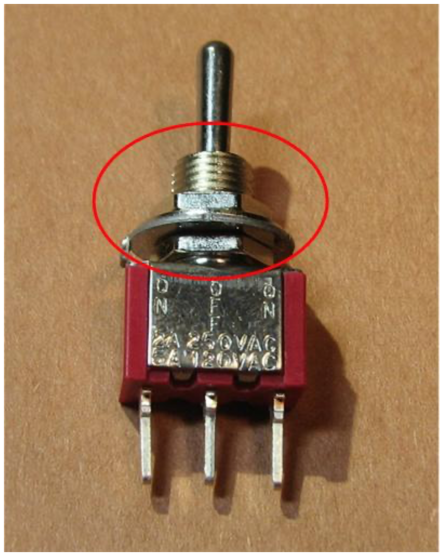
- The first pin is the positive input. Connect the first pin (row 9) in the switch to the positive rail.
- The third pin is the negative input. Connect the third pin (row 13) in the switch to the negative rail.
- The second, or middle, pin is the output. Connect the second or middle pin (row 11) to the final output LED by running a wire from the output (4a) of the switch to the LED (4b) at the bottom of the board.
Figure \(\PageIndex{9}\): Completed circuit 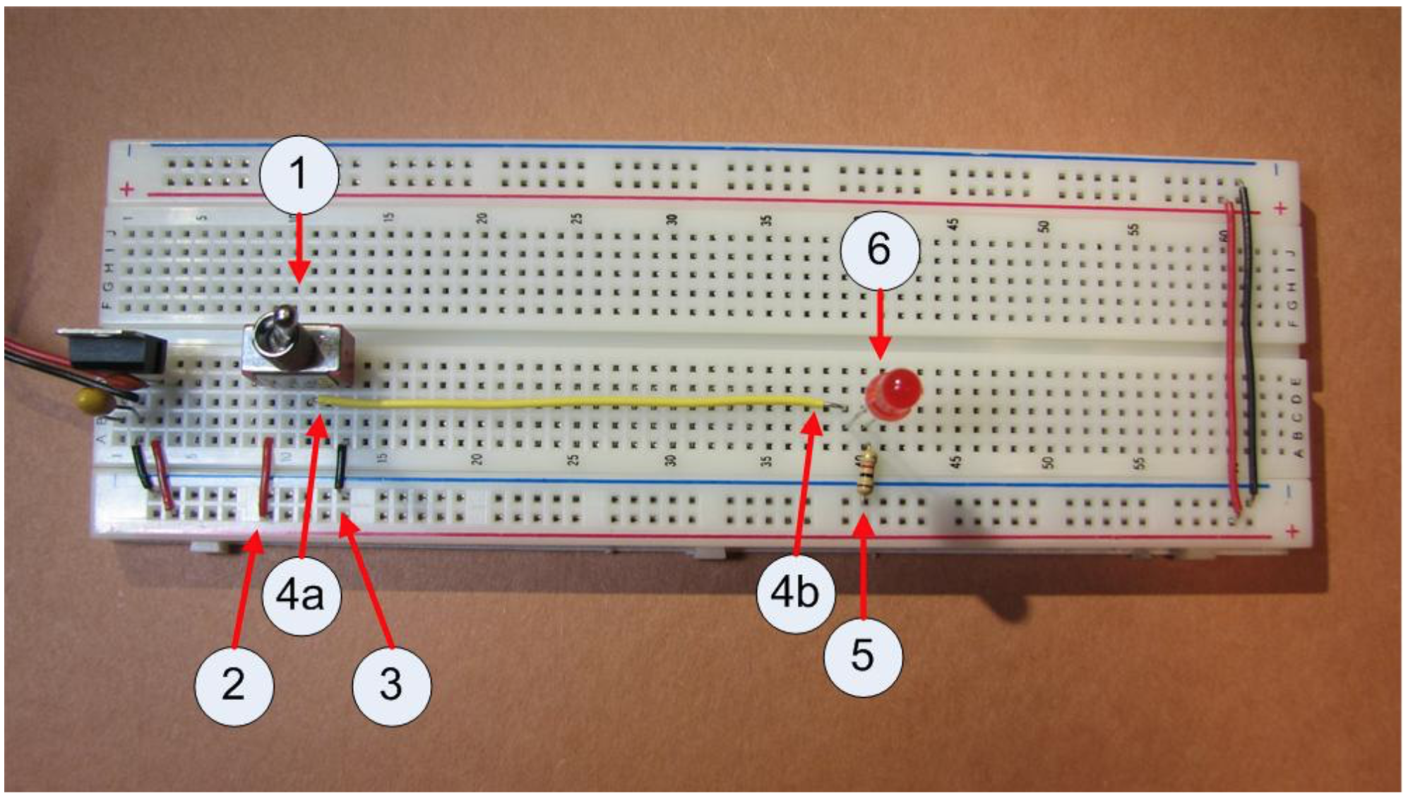
This type of switch always produces the output from the pin opposite the direction of the switch. When the switch is pointing towards the first (positive) input the output of the switch is negative, and when the switch is pointing towards the third (negative) pin the output is positive. There is also a middle position of the switch. The middle position always is an unknown state, so it could go to either positive or negative. Never check a circuit with the switch in the middle position.
The switch is now installed. Again the switch can be tested to see if it is installed correctly connecting the switch output (pin 12) to the negative rail using the LED. If the switch is installed correctly, the switch should turn the LED on and off.
\(\PageIndex{5}\) Completing the Circuit
The circuit can now be completed. The steps below refer to Figure \(\PageIndex{9}\).
- Place a resistor on the row after where you ran the wire in 4b. The resistor is used to lower the current in the circuit so that the LED does not glow as bright, and will not burn out as fast.
- Place a LED on the board between the row for 4b and the resistor. Remember an LED is directional, so you have to orient it correctly. The longer leg should always connect to the positive voltage (4b), and the shorter one to the ground (5). Orient the LED so that the longer leg is closer to the switch (positive), and have the LED cross two rows.
The circuit should be complete. If it is done correctly the switch should turn the LED on and off. Give yourself a pat on the back, you have completed the first circuit.
5 Chips used in circuits generally use either 5 volts or 3.3 volts. The chips used in this book will all work with 5 volts, so the circuits will be powered at 5 volts.