Engineering LibreTexts

7.2: Decoder Circuit

  • Page ID
    26989
  • \( \newcommand{\vecs}[1]{\overset { \scriptstyle \rightharpoonup} {\mathbf{#1}} } \) \( \newcommand{\vecd}[1]{\overset{-\!-\!\rightharpoonup}{\vphantom{a}\smash {#1}}} \)\(\newcommand{\id}{\mathrm{id}}\) \( \newcommand{\Span}{\mathrm{span}}\) \( \newcommand{\kernel}{\mathrm{null}\,}\) \( \newcommand{\range}{\mathrm{range}\,}\) \( \newcommand{\RealPart}{\mathrm{Re}}\) \( \newcommand{\ImaginaryPart}{\mathrm{Im}}\) \( \newcommand{\Argument}{\mathrm{Arg}}\) \( \newcommand{\norm}[1]{\| #1 \|}\) \( \newcommand{\inner}[2]{\langle #1, #2 \rangle}\) \( \newcommand{\Span}{\mathrm{span}}\) \(\newcommand{\id}{\mathrm{id}}\) \( \newcommand{\Span}{\mathrm{span}}\) \( \newcommand{\kernel}{\mathrm{null}\,}\) \( \newcommand{\range}{\mathrm{range}\,}\) \( \newcommand{\RealPart}{\mathrm{Re}}\) \( \newcommand{\ImaginaryPart}{\mathrm{Im}}\) \( \newcommand{\Argument}{\mathrm{Arg}}\) \( \newcommand{\norm}[1]{\| #1 \|}\) \( \newcommand{\inner}[2]{\langle #1, #2 \rangle}\) \( \newcommand{\Span}{\mathrm{span}}\)\(\newcommand{\AA}{\unicode[.8,0]{x212B}}\)

    The implementation of a decoder is based on the idea that all possible combinations of output from a given set of inputs can be generated by using AND operations on combinations of the input and inverted input bits. For example, for the two bits A and B all of the possible combinations of the bits are 00, 01, 10, and 11, or A'B', A'B, AB', and AB.

    Consider the decoder in Figure 7.1.2, which has two inputs and 4 outputs. The implementation of this decoder is given in Figure \(\PageIndex{1}\). There are 2 inputs lines which are split into 4 lines, 2 normal and 2 inverted. These 4 lines are sent to 4 AND gates, each AND gate producing an output for one and only one value from the 2 input lines.

    Figure \(\PageIndex{1}\): Decoder circuit

    Screen Shot 2020-06-26 at 7.44.26 PM.png

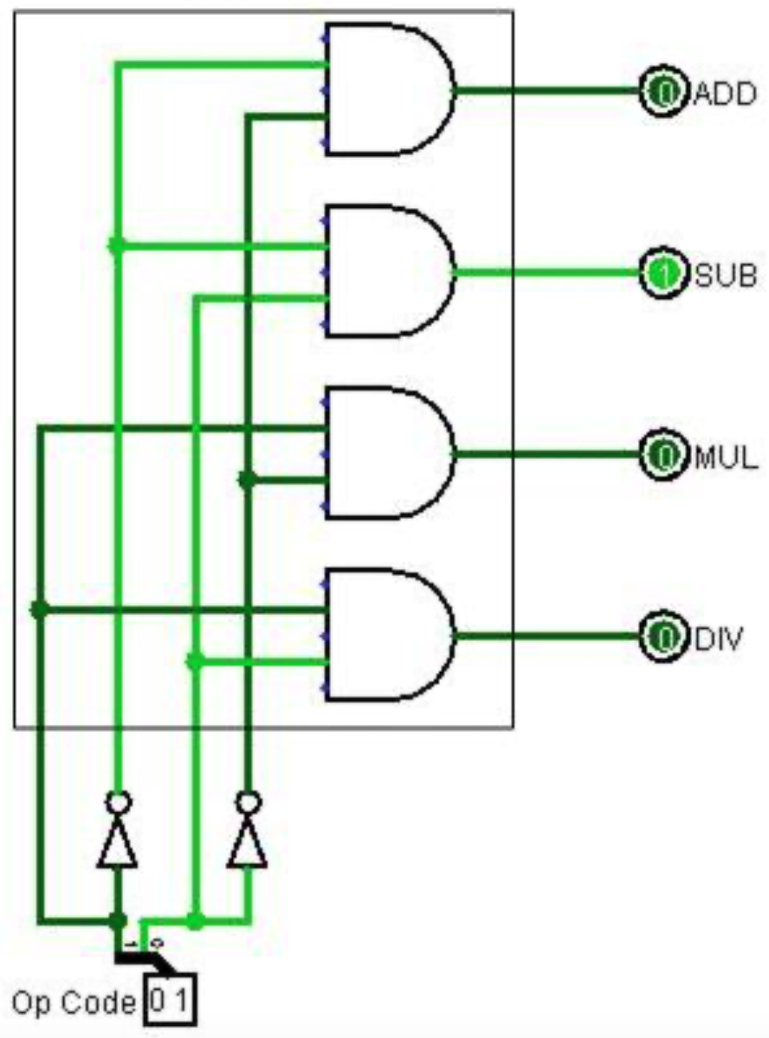
    This shows a decoder is a circuit which enumerates all the values from the input bits by splitting them into separate output lines. A 3-to-8 decoder would have 3 input bits which would use AND and NOT gates to produce 8 output (000, 001, 010, 011, 100, 101, 110, and 111). The implementation of a 3-to-8 decoder is left as an exercise.


    This page titled 7.2: Decoder Circuit is shared under a CC BY 4.0 license and was authored, remixed, and/or curated by Charles W. Kann III via source content that was edited to the style and standards of the LibreTexts platform; a detailed edit history is available upon request.

    • Was this article helpful?