
9.4: Edge Triggered Flip-Flop
- Page ID
- 27005

An edge triggered flip-flop (or just flip-flop in this text) is a modification to the latch which allows the state to only change during a small period of time when the clock pulse is changing from 0 to 1. It is said to trigger on the edge of the clock pulse, and thus is called an edge-triggered flip-flop. The flip-flop can be triggered by a raising edge (0->1, or positive edge trigger) or falling edge (1->0, or negative edge trigger). All flip-flops in this text will be positive edge trigger.
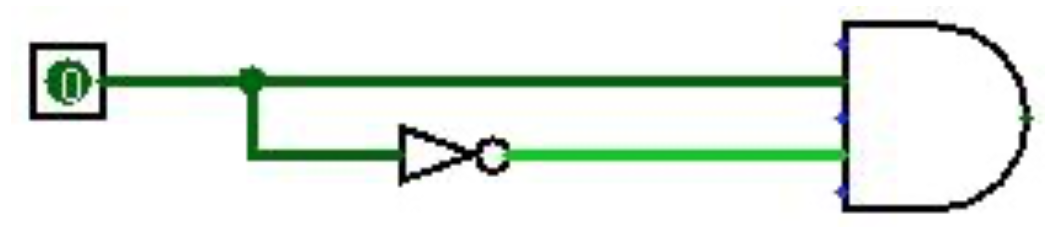
The concept behind a flip-flop is that current flowing within a circuit is not instantaneous, but always has a short delay depending on the size of the circuit, the gates that it must traverse, etc. This is illustrated in Figure \(\PageIndex{1}\). In this diagram, it would appear that the Boolean equation (true^false) is always false, so this circuit should always produce a 0 output. However since there is a small but present lag in the current going over the NOT gate, there is a small but finite period of time when the two inputs to the AND gate would both be 1 (when the clock is transitioning from 0 to 1), and the output of the circuit would be 1.
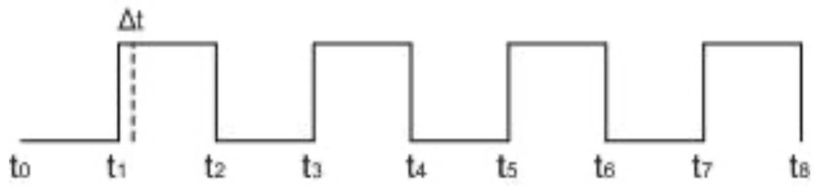
This amount of time, Δt, is shown on the square wave diagram in Figure \(\PageIndex{2}\). This time is called a raising edge trigger, and it is during this time interval that the above circuit would be 1.
This short delay can be used to change the circuit such that it will only change during this brief edge trigger. Because Δt is smaller than any combinational logic, this removes the need to create a second latch to maintain a valid state. A circuit which implements this concept is shown in Figure \(\PageIndex{3}\).
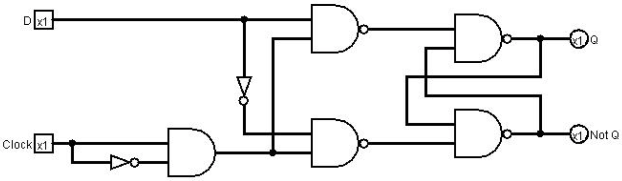
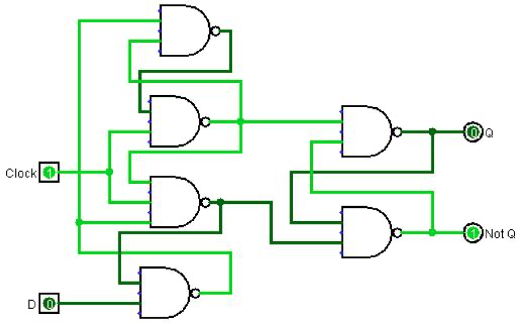
The problem with the circuit in Figure \(\PageIndex{3}\) is that it cannot guarantee that the time delay caused by the edge trigger is sufficient to allow the latch logic to obtain the correct state. The circuit in Figure \(\PageIndex{4}\) is a true implementation of a flip-flop. While it appears much more complex than the implementation in the Figure \(\PageIndex{3}\), it is left as an exercise to show that it contains exactly the same number of gates as the example above.
Due to a problem known as debouncing, it is hard to illustrate a flip-flop in isolation as a circuit. So this chapter will not implement a flip-flop. However, a flip-flop will be used as part of the circuits in chapter 10.