
3.4: Debugging the Circuit
- Page ID
- 26963

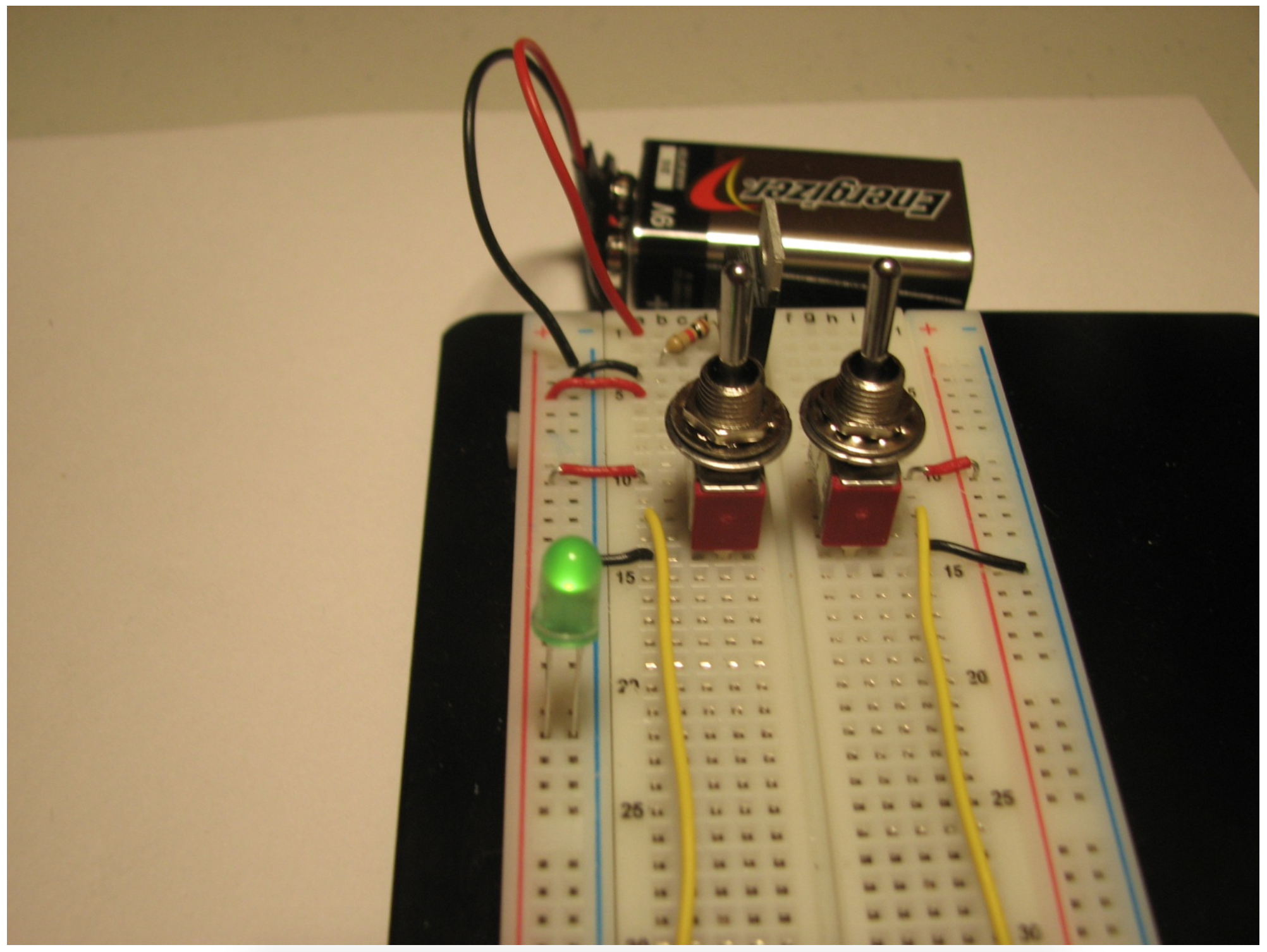
Sometimes, despite our best efforts, things simply do not work. If your circuit does not work at this point, it will have to be corrected, or debugged. The easiest way to debug this circuit is using an LED. At each step in the implementation, the voltage (positive and negative) for some points on the board will be known. For example, once the power has been supplied to the breadboard, the red rail is positive and the blue rail is negative. Placing a LED (correctly oriented) between these two should light that LED, as in Figure \(\PageIndex{1}\). If the LED does not light, move backwards through the components in the board until you reach a point where the LED does light as you expect. Alternatively, you can start with the battery snap, and move forward in the circuit until you find a point where the LED fails. In this fashion you can determine to what point the circuit works. The step between where the circuit is working and the circuit is not working is in error, and needs to be debugged.
Here is a tip I have learned from 30 years of debugging. The simplest rule for debugging a circuit, program, or life is to allow what you are fixing to tell you what is actually true, not what you believe should be (or even must be) true. Do not try to reason about what should be happening. See what is actually happening, and then try to explain the observed results. Just verbalizing the problem can help6. When you get too upset, take a walk and get your mind off of the problem.
But the key is to not assume you know what must be happening. Allowing the situation to tell you the truth about what is happening is always more fruitful then trying to find faults in your logic, especially if you believe that your (what turns out to be errant) logic has to be correct.
6 I like to tell the problem to a dog. Unlike a person, he will listen intently and not interrupt. And he appreciates the attention.