
6.2: Half Adder
- Page ID
- 26982

The circuit presented in this section is called a half adder. A half adder is an adder which adds two binary digits together, resulting in a sum and a carry.
Why is it called a half adder? Because this adder can only be used to add two binary digits, it cannot form a part of an adder circuit that can add two n-bit binary numbers. The adder circuit which will be used to add n-bit binary numbers is called a full adder. This adder is less than a full adder, and hence it is called a half adder.
\(\PageIndex{1}\) Adding binary numbers
To understand binary addition, we must remember how we did addition when we first learned it. When executing decimal addition for any two digits, the result can have 2 digits. For example 7+6= 13. The first digit (in this case 1) is called the carry (C), and the second digit is called the sum (S). The purpose of the carry is to be included in the addition of the next digit of the number. For example, to calculate 17 + 26, first the 7+6 operation is performed, and the digit 3 is moved to the answer. The carry 1 is added to tens digits from 17 and 26 (1+1+2) to give the number 4, and the answer is combined to produce 43.
Thus the carry digit is carried to the addition in the next digit. So when adding two digits the output from the operation is a sum and a carry. Remember that a carry always produced, even if it is 0. To calculate 14+22, the 4 and 2 are added, resulting in a 6 with a carry of 0. This is important to remember, every addition results in a sum and carry, though the carry can be 0.
Binary addition for two binary numbers each containing one digit works the same way as decimal addition for two decimal one digit numbers, but is simpler because the two input values can only have 2 states (either 0 or 1). So give two binary inputs to an addition (X and Y) we can summarize the possible results of adding those bits in the following truth table. Note that the added values produce two results, a sum and a carry, both of which are either 0 or 1.
|
Input |
Output |
||
| X | Y | S | C |
| 0 | 0 | 0 | 0 |
| 0 | 1 | 1 | 0 |
| 1 | 0 | 1 | 0 |
| 1 | 1 | 0 | 1 |
\(\PageIndex{2}\) Half adder circuit
The truth table in Figure \(\PageIndex{1}\) shows that the outputs S and C are simply binary functions on X and Y. Specifically the S output is the result of an XOR operation X⊕Y. The C output is the result of an AND operation, X*Y. This circuit can be designed and implemented in Logisim, as shown in Figure \(\PageIndex{2}\).
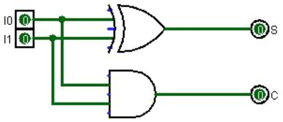
This simple circuit adds two inputs, I0 and I1, and produces a sum and carry. This is the first circuit that we have implemented that has two outputs. This is not a problem. Any number of functions can be applied to a set of input data, and a single set of input data can result in any number of outputs.
\(\PageIndex{3}\) Half adder implementation
This section will show how to implement the half-adder as a circuit on the breadboard. The circuit has 2 inputs (X and Y), so it will require two switches. The circuit has 2 outputs, thus it has 2 LEDs, one LED for the carry, and one LED for the sum.
The circuit needs to use two chips since chips can contain multiple gates, but all of the gates on the chip are of the same type. This circuit needs one chip for the XOR gate and one chip for the AND gate. The 2 chips being used are the 7408 AND chip, and the 7486 XOR chip. Both of these chips are quad (4) gate chips, but this circuit will only use one gate on each chip.
The implementation of the half adder is shown in Figure \(\PageIndex{4}\), and the following steps refer to that figure.
- Place two switches, which will be the X and Y input, on the breadboard, and connect them as in previous labs.
- Place the 7486 (XOR gate) chip on the breadboard and power the chip as in previous projects by connecting pin 7 to the ground rail, and pin 14 to the positive rail. The pin configuration for the 7486 chip is given in Figure \(\PageIndex{3}\).
Figure \(\PageIndex{3}\): 7486 pin configuration diagram 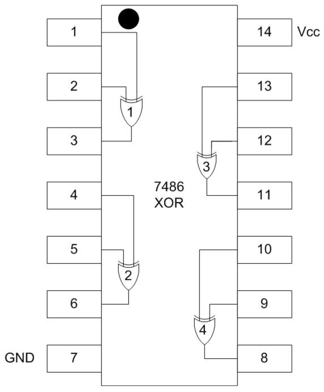
- Place the 7408 (AND gate) chip on the breadboard and power the chip as in previous projects by connecting pin 7 to the ground rail, and pin 14 to the positive rail for both chips.
- Connect both switch X and Y to the input of the third XOR gate (pins 12 and 13) on the 7486 chip. Connect the output for the XOR gate (pin 11) to the input for the green, or sum, LED.
Figure \(\PageIndex{4}\): Half adder implementation 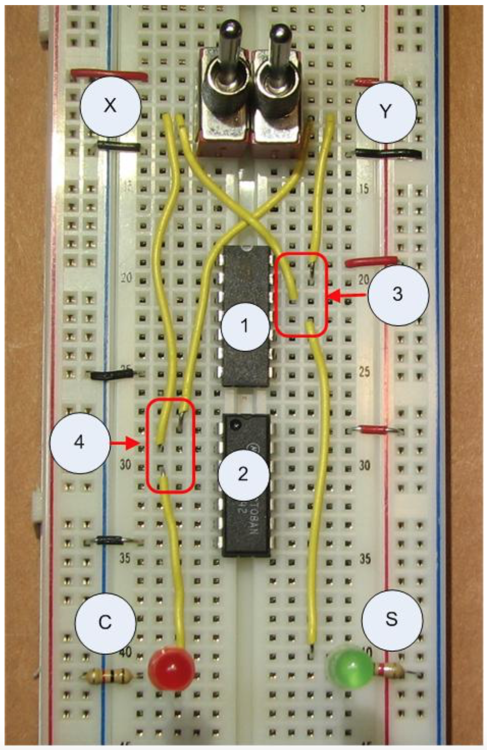
- Connect both switch X and Y to the input of the first AND gate (pins 1 and 2) on the 7408 chip. Connect the output for the AND gate (pin 3) to the input for the red, or carry, LED.
The circuit should now be dark if both switches are off, the green LED should light if only one switch is on, and the red LED should light if both switches are on.