
8.1: Introduction
- Page ID
- 26995

A multiplexer (or MUX) is a selector circuit, having log(N) select lines to choose an output from N input values. In a CPU, multiplexers are used to select the correct memory location values to send to the ALU, as shown below.
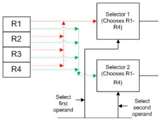
MUXes have two types of inputs. The first type of input is the values to be selected from. In Figure \(\PageIndex{1}\) this input is the value contained in each memory location. Every memory location sends its value to both MUXes, the 4 values on the red line to Mux 1, and the 4 values on the green line to Mux 2. Thus both MUXes have all of the values from all memory to select from.
The second type of input is a set of selection bits which tells the MUX which of the inputs to choose. In Figure \(\PageIndex{1}\) this input is the two select lines coming from the CU. The two bits on each select line tell each MUX which of the 4 input values to choose.
The MUX in Figure \(\PageIndex{1}\) is selecting between n-bit values. The size, in bits, of the data value is called the data width. A data value which can contain the values 0..4 is represented by 2 bits, and so has a data width of 2; a data value which can contain the values 0..16 has a data width of 4; a data value which can contain the values 0..256 has a data width of 8; etc.
If the memory in Figure \(\PageIndex{1}\) had a data width of 8, it would select 8 bits from each of 4 inputs, and be called an 8 bit 4-to-1 multiplexer. Thus a MUX has some number of inputs to choose from, and simply forwards one of these inputs to the output.
The most basic type of MUX, the one on which all larger MUXes are built, is a 1 bit MUX. As will be shown later in this section 8 bit 4-to-1 MUX is made up of eight 1 bit 4-to-1 MUX. So to understand multiplexers a 1 bit 4-to-1 multiplexer will be examined.
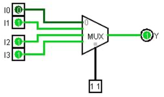
A 1 bit 4-to-1 multiplexer has four 1-bit data inputs values (I0-I3) to choose from. Each bit value I0-I3 can either be 0 or 1. For example, if I0 is selected, the output will be either the value in I0, and either 0 or 1, and the other values of I1, I2, and I3 are simply ignored. The following truth table characterizes this MUX based on the selection bits (S0-S1)
|
Input |
Output |
|
|
S1 |
Y |
|
|
0 |
0 |
I0 |
|
0 |
1 |
I1 |
| 1 | 0 |
I2 |
| 1 | 1 |
I3 |
Note that when a line is selected, either a 0 or a 1 will be passed through to Y. The value of input bit is placed on the output value Y. So in the figure below, if S1S0 are 00, Y is 0. If S0S1 are 01, Y is 1, etc..
To allow a MUX with a larger data width, multiple MUXes are used. Figure \(\PageIndex{4}\) shows two 4-to-1 MUXes linked together to choose one 2-bit output from four 2-bit inputs, thus creating a 2 bit 4-to-1 MUX.
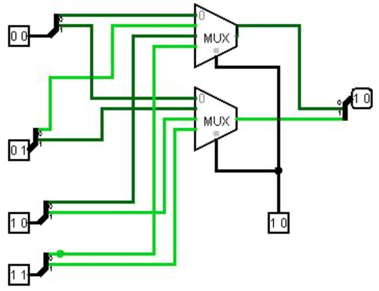
The concept of linking MUXes in this manner can be expanded to produce a MUX that can have any size data width needed. If you want to select an N bits of data (a data width of N), you need N MUXes.
In a CPU the purpose of a MUX is to allow a circuit to select one input from a set of inputs. For example, consider the following circuit, which implements an adder to add two 8 bit numbers. The first number to be added comes from Memory Set 1, and the second number from Memory Set 2. Each set contains four 8-bit values. The MUXes in this circuit choose which item from each Memory Set to use in the addition. For the first set the select bits are set to binary 01, and the second value, binary 00000010, is selected. For the second set the select bits are set to binary 10 and the third value, binary 01000000, is selected. The two values are added together to produce the answer 01000010.
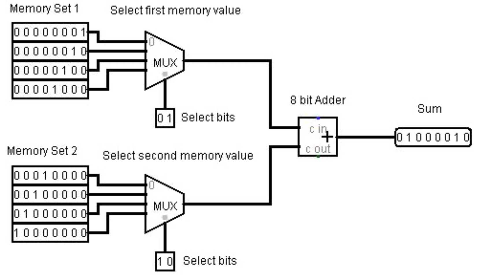
As this example shows, a MUX allows an input value of any fixed data width to be selected based on the value of select bits. The number of inputs which can be chosen from is 2s, where s is the number of select bits.