
2.1: Introduction
- Page ID
- 41257

An antenna interfaces circuits with free-space with a transmit antenna converting a guided wave signal on a transmission line to an electromagnetic (EM) wave propagating in free space, while a receive antenna is a transducer that converts a free-space EM wave to a guided wave on a transmission line and eventually to a receiver circuit. Together the transmit and receive antennas are part of the RF link. The RF link is the path between the output of the transmitter circuit and the input of the receiver circuit (see Figure \(\PageIndex{1}\)). Usually this path includes the cable from the transmitter to the transmit antenna, the transmit antenna itself, the propagation path, the receive antenna, and the transmission line connecting the receive antenna to the receiver circuit. The received signal is much smaller than the transmitted signal. The overwhelming majority of the loss is from the propagation path as the EM signal spreads out, and usually diffracts, reflects, and is partially blocked by objects such as hills and buildings.
The first half of this chapter is concerned with the properties of antennas. One of the characteristics of antennas is that the energy can be focused in a particular direction, a phenomenon captured by the concept of antenna gain, which can partially compensate for path loss. The second half of this chapter considers modeling the RF link and the geographical arrangement of antennas that manage interference from other radios while providing support for as many users as possible.
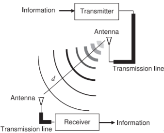
Figure \(\PageIndex{1}\): RF link.
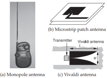
Figure \(\PageIndex{2}\): Representative resonant, (a) and (b), and traveling-wave, (c), antennas.
Example \(\PageIndex{1}\): Interference
In the figure there are two transmitters, \(\text{Tx}_{1}\) and \(\text{Tx}_{2}\), operating at the same power level, and one receiver, \(\text{Rx}\). \(\text{Tx}_{1}\) is an intentional transmitter and its signal is intended to be received at \(\text{Rx}\). \(\text{Tx}_{1}\) is separated from \(\text{Rx}\) by \(D_{1} = 2\text{ km}\). \(\text{Tx}_{2}\) uses the same frequency channel as \(\text{Tx}_{1}\), and as far as RX is concerned it transmits an interfering signal. Assume that the antennas are omnidirectional (i.e., they transmit and receive signals equally in all directions) and that the transmitted power density drops off as \(1/d^{2}\), where \(d\) is the distance from the transmitter. Calculate the signal-to-interference ratio (SIR) at \(\text{Rx}\).
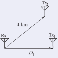
Figure \(\PageIndex{3}\)
Solution
\(D_{1} = 2\text{ km}\) and \(D_{2} = 4\text{ km}\).
\(P_{1}\) is the signal power transmitted by \(\text{Tx}_{1}\) and received at \(\text{Rx}\).
\(P_{2}\) is the interference power transmitted by \(\text{Tx}_{2}\) and received at \(\text{Rx}\).
So \(\text{SIR} =\frac{P_{1}}{P_{2}}=\left(\frac{D_{2}}{D_{1}}\right)^{2}=4=6.02\text{ dB}\).
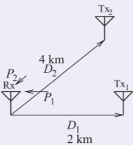
Figure \(\PageIndex{4}\)