
2.2: RF Antennas
- Page ID
- 41258

Antennas are of two fundamental types: resonant and traveling-wave antennas, see Figure 2.1.2. Resonant antennas establish a standing wave of current with required resonance usually established when the antenna section is either a quarter- or half-wavelength long. These antennas are also known as standing-wave antennas. Resonant antennas are inherently narrowband because of the resonance required to establish a large standing wave of current. Figures 2.1.2(a and b) show two representative resonant antennas. The physics of the operation of a resonant antenna is understood by considering the time domain. First consider the physical operation of a transmit antenna. When a sinusoidal voltage is applied to the conductor
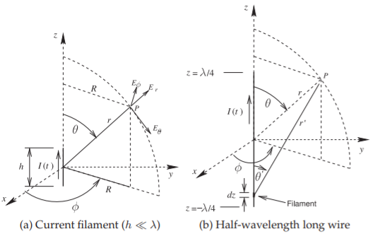
Figure \(\PageIndex{1}\): Wire antennas. The distance from the center of an antenna to the field point \(P\) is \(r\). \(R = r\sin θ\).
of an antenna, charges, i.e. free electrons, accelerate or decelerate under the influence of an applied voltage source which typically arrives at the antenna from a traveling wave voltage on a transmission line. When the charges accelerate (or decelerate) they produce an EM field which radiates away from the antenna. At a point on the antenna there is a current sinusoidally varying in time, and the net acceleration of the charges (in charge per second per second) is also sinusoidal with an amplitude that is directly proportional to the amplitude of the current sinewave. Hence having a large standing wave of current, when the antenna resonates sinusoidally, results in a large charge acceleration and hence large radiated fields.
When an EM field impinges upon a conductor the field causes charges to accelerate and hence induce a voltage that propagates on a transmission line connected to the receive antenna. Traveling-wave antennas, an example of one is shown in Figures 2.1.2(c), operate as extended lines that gradually flare out so that a traveling wave on the original transmission line transitions into free space. Traveling-wave antennas tend to be two or more wavelengths long at the lowest frequency of operation. While relatively long, they are broadband, many \(3\) or more octaves wide (e.g. extending from \(500\text{ MHz}\) to \(4\text{ GHz}\) or more). These antennas are sometimes referred to as aperture antennas.