
6.5: Directional Coupler
- Page ID
- 41294

Coupling can be exploited to realize a new type of element called a directional coupler. The schematic of a directional coupler is shown in Figure \(\PageIndex{1}\)(a) and a microstrip realization is shown in Figure \(\PageIndex{1}\)(b). A usable directional coupler has a coupled line length of at least one-quarter
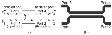
Figure \(\PageIndex{1}\): Directional couplers: (a) schematic; and (b) backward-coupled microstrip coupler. (Note that not all couplers are backward-wave couplers as shown in (a).)
| Parameter | Ideal | Ideal (\(\text{dB}\)) | Typical |
|---|---|---|---|
| Coupling, \(C\) | \(-\) | \(-\) | \(3-40\text{ dB}\) |
| Transmission, \(T\) | \(|\sqrt{1-1/C^{2}}|\) | \(20\log |\sqrt{1-1/C^{2}}|\) | \(-0.5\text{ dB}\) |
| Directivity, \(D\) | \(∞\) | \(∞\) | \(40\text{ dB}\) |
| Isolation, \(I\) | \(∞\) | \(∞\) | \(40\text{ dB}\) |
Table \(\PageIndex{1}\): Ideal and typical parameters of a directional coupler.
wavelength, with longer lengths of line resulting in broader bandwidth operation. Directional couplers are used to sample a traveling wave on one line and to induce a usually much smaller image of the wave on another line. That is, the forward- and backward-traveling waves are separated. Here a prescribed amount of the incident power is coupled out of the system. Thus, for example, a \(20\text{ dB}\) microstrip coupler is a pair of coupled microstrip lines in which \(1/100\) of the power input is coupled from one microstrip line onto the another.
Referring to Figure \(\PageIndex{1}\), a coupler is specified in terms of the following parameters (always check the magnitude of the factors, as some papers and books on couplers use the inverse of the \(C\) used here):
- Coupling factor:
\(\begin{array}{lll}{C=V_{1}^{+}/V_{3}^{-}}&{=}&{\text{inverse of the voltage fraction "transferred"}}\\{}&{}&{\text{(coupled) across to the opposite arm }(C>1).}\end{array}\) - Transmission factor (inverse of insertion loss):
\(\begin{array}{lll}{T=V_{2}^{-}/V_{1}^{+}}&{=}&{\text{transmission directly through the "primary" arm}}\\{}&{}&{\text{of the structure }(T<1).}\end{array}\) - Directivity factor:
\(\begin{array}{lll}{D=V_{3}^{-}/V_{4}^{-}}&{=}&{\text{measure of the undesired coupling from Port 1 to}}\\{}&{}&{\text{Port 4 relative to the signal level at Port 3 }(D>1).}\end{array}\) - Isolation factor:
\(\begin{array}{lll}{I=V_{1}^{+}/V_{4}^{-}}&{=}&{\text{isolation between Port 4 and Port 1 }(I>1).}\end{array}\)
It is usual to quote these quantities in decibels. For example, the coupling factor in decibels is \(C|_{\text{dB}} = 20 \log C\). So \(20\text{ dB}\) coupling indicates that the coupling factor is \(10\). An ideal quarter-wave coupler has \(D = ∞\) (i.e., infinite directivity) and
\[\label{eq:1}C=\frac{Z_{0e}+z_{0o}}{Z_{0e}-Z_{0o}} \]
In decibels the coupling is
\[\label{eq:2}C|_{\text{dB}} = 20\log\left(\frac{Z_{0e}+Z_{0o}}{Z_{0e}-Z_{0o}}\right) \]
Typical and ideal parameters of a directional coupler are given in Table \(\PageIndex{1}\). Since an ideal coupler does not dissipate power, the magnitude of the transmission coefficient is
\[\label{eq:3}|T|=|\sqrt{1-1/C^{2}}| \]
There are many types of directional couplers, and the phases of the traveling waves at the ports will not necessarily coincide. The microstrip coupler shown in Figure \(\PageIndex{1}\)(b) has maximum coupling when the lines are one-quarter wavelength long.\(^{1}\) At the frequency where they are one-quarter
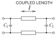
Figure \(\PageIndex{2}\): Parallel coupled lines with lumped capacitors reducing the length of the coupled lines.
wavelength long, the phase difference between traveling waves entering at Port 1 and leaving at Port 2 will be \(90^{\circ}\).
Example \(\PageIndex{1}\): Directional Coupler Isolation
A lossless directional coupler has coupling \(C = 20\text{ dB}\), transmission factor \(0.8\), and directivity \(20\text{ dB}\). What is the isolation? Express your answer in decibels.
Solution
Coupling factor: \(C=V_{1}^{+}/V_{3}^{-}\)
Transmission factor: \(T=V_{2}^{-}/V_{1}^{+}\)
Directivity factor: \(D=V_{3}^{-}/V_{4}^{-}\)
Isolation factor: \(I=V_{1}^{+}/V_{4}^{-}\)
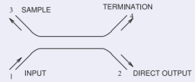
Figure \(\PageIndex{3}\)
\[D=20\text{ dB}=10\quad\text{and}\quad C=20\text{ dB}=10\nonumber \]
so the isolation is
\[I=\frac{V_{1}^{+}}{V_{4}^{-}}=\frac{V_{3}^{-}}{V_{4}^{-}}\cdot\frac{V_{1}^{+}}{V_{3}^{-}}=D\cdot C=10\cdot 10=100=40\text{ dB}\nonumber \]
6.5.1 Directional Coupler with Lumped Capacitors
Directional couplers using only coupled transmission lines can be large at low frequencies, as the minimum length is approximately one-quarter of a wavelength. This can be a problem at RF and low microwave frequencies, say, below \(3\text{ GHz}\). The length of the line can be reduced by incorporating lumped elements, as shown in Figure \(\PageIndex{2}\)(a).
Footnotes
[1] This is shown in a detailed derivation provided in Section 11.4 of [1].