
7.5: Scattering Parameters and Coupled Lines
- Page ID
- 41302

Directional couplers were described in Section 6.5, but without the use of \(S\) parameters. A directional coupler with ports defined as in Figure 7-6, and with the ports matched (so that \(S_{11} =0= S_{22} = S_{33} = S_{44}\)), has the following scattering parameter matrix:
\[\label{eq:1}\mathbf{S} =\left[\begin{array}{cccc}{0}&{T}&{1/C}&{1/I}\\{T}&{0}&{1/I}&{1/C}\\{1/C}&{1/I}&{0}&{T}\\{1/I}&{1/C}&{T}&{0}\end{array}\right] \]
There are many types of directional couplers, and the phases of the traveling waves at the ports will not necessarily be in phase as Equation \(\eqref{eq:1}\) implies. When the phase difference between traveling waves entering at Port 1 and leaving at Port 2 is \(90^{\circ}\), Equation \(\eqref{eq:1}\) becomes
\[\label{eq:2}\mathbf{S} =\left[\begin{array}{cccc}{0}&{-\jmath T}&{1/C}&{1/I}\\{-\jmath T}&{0}&{1/I}&{1/C}\\{1/C}&{1/I}&{0}&{-\jmath T}\\{1/I}&{1/C}&{-\jmath T}&{0}\end{array}\right] \]
Example \(\PageIndex{1}\): Identifying Ports of a Directional Coupler
A directional coupler has the following \(S\) parameters:
\[S=\left[\begin{array}{cccc}{0}&{0.9}&{0.001}&{0.1}\\{0.9}&{0}&{0.1}&{0.001}\\{0.001}&{0.1}&{0}&{0.9}\\{0.1}&{0.001}&{0.9}&{0}\end{array}\right]\nonumber \]
- What are the through (i.e., transmission) paths? Identify two paths. That is, identify the pairs of ports at the ends of the through paths.
First note that the assignment of ports to a directional coupler is arbitrary. So the \(S\) parameters need to be considered to figure out how the ports are related. The \(S\) parameters relate the forward-traveling waves to the backward-traveling waves and this leads to the required understanding, thus
\[\left[\begin{array}{c}{V_{1}^{-}}\\{V_{2}^{-}}\\{V_{3}^{-}}\\{V_{4}^{-}}\end{array}\right] =S\left[\begin{array}{c}{V_{1}^{+}}\\{V_{2}^{+}}\\{V_{3}^{+}}\\{V_{4}^{+}}\end{array}\right] = \left[\begin{array}{cccc}{0}&{0.9}&{0.001}&{0.1}\\{0.9}&{0}&{0.1}&{0.001}\\{0.001}&{0.1}&{0}&{0.9}\\{0.1}&{0.001}&{0.9}&{0}\end{array}\right] \left[\begin{array}{c}{V_{1}^{+}}\\{V_{2}^{+}}\\{V_{3}^{+}}\\{V_{4}^{+}}\end{array}\right]\nonumber \]
Writing the S parameters out this way makes it easier to identify the largest backward traveling waves for each of the inputs at Ports 1, 2, 3, and 4. The backward-traveling wave will leave the directional coupler and the inputs will be forward-traveling waves.
Consider Port 1, the largest backward-traveling wave is at Port 2, and so Ports 1 and 2 define one of the through paths. The other through path is between Ports 3 and 4. So the through paths are 1–2 and 3–4. - What is the coupled port for the signal entering Port 1?
The coupled port is identified by the port with the largest backward-traveling signal not including the port at the other end of the through path. For Port 1 the coupled port is Port 4. - What is the coupling factor?
\[C=\frac{V_{1}^{+}}{V_{4}^{-}}=\frac{1}{0.1}=10=20\text{ dB}\nonumber \] - What is the isolated port for the signal entering Port 1?
The isolated port is Port 3. The backward-traveling wave at this port is the smallest given an input at Port 1. - What is the isolation factor?
\[I=\frac{V_{1}^{+}}{V_{3}^{-}}=\frac{1}{0.001}=1000=60\text{ dB}\nonumber \] - What is the directivity factor?
The directivity factor indicates how much stronger the signal is at the coupled port compared to the isolated port for a signal at the input. For an input at Port 1, the directivity factor is
\[D=\frac{V_{4}^{-}}{V_{3}^{-}}=\frac{0.1}{0.001}=100=40\text{ dB}\nonumber \]
As a check \(D = I/C = 1000/10 = 100\). - Draw a schematic of the directional coupler.
There are four ways to draw it depending on the input port chosen, see Figure \(\PageIndex{2}\).
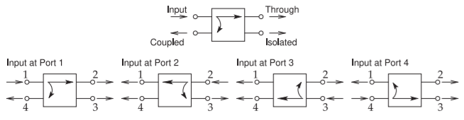
Figure \(\PageIndex{2}\): Directional coupler schematic drawn with each of the four possible input ports.