
9.3: Surface-Mount Components
- Page ID
- 41314

The majority of the RF and microwave design effort goes into developing modules and interconnecting modules on circuit boards. With these the most common type of component to use is a surface-mount component. Figure \(\PageIndex{1}\)(a) shows a two-terminal element, such as a resistor or capacitor, in the form of a surface-mount component. Figure \(\PageIndex{1}\)(b and c) show the use of surface-mount components on a microwave circuit board.
A two-terminal surface-mount resistor or capacitor is commonly called a chip resistor or chip capacitor. These can be very small, and the smaller the component often the higher the operating frequency due to reduced parasitic capacitance or inductance. Common sizes of two-terminal chip components are listed in Table \(\PageIndex{1}\). The resonance when a chip capacitor (inductor) resonates with the parasitic inductance (capacitance) is called self-resonance and the resonant frequency is called the self-resonance frequency. Figure \(\PageIndex{2}\)(a) shows an inductor in a surface-mount package and details are shown in Figure \(\PageIndex{2}\)(b) and the inductor is useable as an inductor at a frequency backed-off from the SRF, see Table 9.4.1.
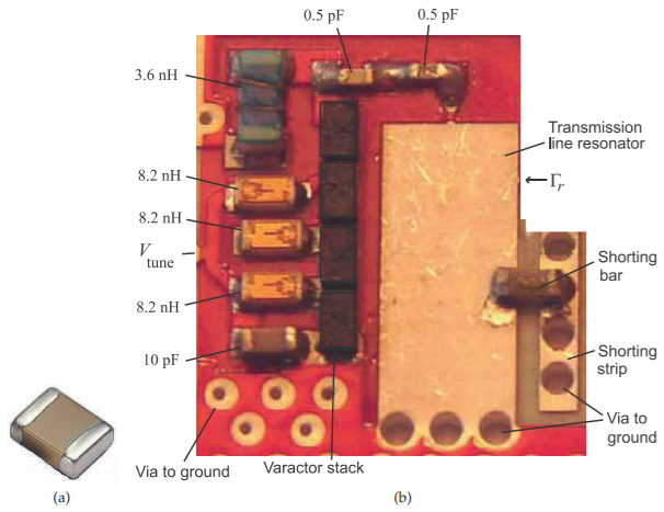
Figure \(\PageIndex{1}\): Circuit board showing the use of surface-mount components: (a) chip resistor or capacitor with metal terminals at the two ends; and (b) a populated RF microstrip circuit board of a \(5\text{ GHz}\) tunable resonator [1]. The larger components have dimensions \(1.6\text{ mm}\times 0.8\text{ mm}\). The shorting bar is a \(0\:\Omega\) chip resistor.
| Designation | Size \((\text{inch }\times\text{ inch})\) | Metric Designation | Size \((\text{mm }\times\text{ mm})\) |
|---|---|---|---|
| \(01005\) | \(0.016 \times 0.0079\) | \(0402\) | \(0.4 \times 0.2\) |
| \(0201\) | \(0.024 \times 0.012\) | \(0603\) | \(0.6 \times 0.3\) |
| \(0402\) | \(0.039 \times 0.020\) | \(1005\) | \(1.0 \times 0.5\) |
| \(0603\) | \(0.063 \times 0.031\) | \(1608\) | \(1.6 \times 0.8\) |
| \(0805\) | \(0.079 \times 0.049\) | \(2012\) | \(2.0 \times 1.25\) |
| \(1008\) | \(0.098 \times 0.079\) | \(2520\) | \(2.5 \times 2.0\) |
| \(1206\) | \(0.13 \times 0.063\) | \(3216\) | \(3.2 \times 1.6\) |
| \(1210\) | \(0.13 \times 0.098\) | \(3225\) | \(3.2 \times 2.5\) |
| \(1806\) | \(0.18 \times 0.063\) | \(4516\) | \(4.5 \times 1.6\) |
| \(1812\) | \(0.18 \times 0.13\) | \(4532\) | \(4.5 \times 3.2\) |
| \(2010\) | \(0.20 \times 0.098\) | \(5025\) | \(5.0 \times 2.5\) |
| \(2512\) | \(0.25 \times 0.13\) | \(6432\) | \(6.4 \times 3.2\) |
| \(2920\) | \(0.29 \times 0.20\) | \(–\) | \(7.4 \times 5.1\) |
Table \(\PageIndex{1}\): Sizes and designation of two-terminal surface mount components. Note the designation of a surface-mount component refers (approximately) to its dimensions in hundredths of an inch.
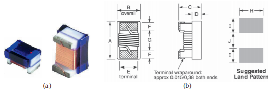
Figure \(\PageIndex{2}\): : Chip inductor: (a) in an 0603 surface-mount package; and (b) schematic showing sizes and pads to be provided on a circuit board (\(A=64\text{ mils}\) (\(1.63\text{ mm}\)),\( B=33\text{ mils}\) (\(0.84\text{ mm}\)), \(C=24\text{ mils}\) (\(0.61\text{ mm}\)), \(D=13\text{ mils}\) (\(0.33\text{ mm}\)), \(E=30\text{ mils}\) (\(0.76\text{ mm}\)), \(F=25\text{ mils}\) (\(0.64\text{ mm}\)), \(G=25\text{ mils}\) (\(0.64\text{ mm}\)), and \(H=40\text{ mils}\) (\(1.02\text{ mm}\))). Copyright Coilcraft, Inc., used with permission [2].