
9.9: Baluns
- Page ID
- 41320

A balun [7, 8] is a structure that joins balanced and unbalanced circuits. The word itself (balun) is a contraction of balanced-to-unbalanced transformer. Representations of a balun are shown in Figure 9.6.2. A situation when a balun is required is with an antenna. Many antennas do not operate correctly if part of the antenna is at the same potential electrically as the ground. Instead, the antenna should be electrically isolated from the ground (i.e., balanced). The antenna would usually be fed by a coaxial cable with its outer conductor connected to ground.
The schematic of a magnetic transformer used as a balun is shown in Figure 9\(\PageIndex{1}\)(a) with one terminal of the unbalanced port grounded. Figure 9.6.2(b) is the standard schematic symbol for a balun and its use with a dipole antenna is shown in Figure 9.6.2(c). The second port is floating and is not referenced to ground. An example of the use of a balun is shown in Figure \(\PageIndex{1}\)(b), where the output of a single-ended amplifier is unbalanced, being referred to ground. A balun transitions from the unbalanced transistor output to a balanced output.
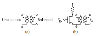
Figure \(\PageIndex{1}\): Balun: (a) schematic representation as a transformer showing unbalanced and balanced ports; and (b) connected to a single-ended unbalanced amplifier yielding a balanced output.
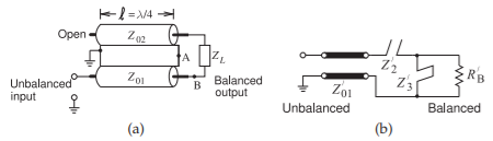
Figure \(\PageIndex{2}\): Marchand balun: (a) coaxial form of the Marchand balun; and (b) its equivalent circuit.
9.7.1 Marchand Balun
The most common form of microwave balun is the Marchand balun [7, 9, 10, 11, 12]. An implementation of the Marchand balun using coaxial transmission lines is shown in Figure \(\PageIndex{2}\)(a) [13]. The \(Z_{2}\) line acts as both a series stub and a shunt stub. Thus the model of the Marchand balun is as shown in Figure \(\PageIndex{2}\)(b).